
Installation Instructions
Page 1
...slightly from the illustration in Rear Wall 7 Attach Mounting Plate to Wall 8 Prepare Upper Cabinet 8 Install Damper Assembly 9 Install the Microwave Oven 9 Complete Installation 10 VENTING DESIGN SPECIFICATIONS 11 ASSISTANCE 12 Replacement Parts 12 Accessories 12 MICROWAVE HOOD COMBINATION SAFETY Your safety... tell you how to and including 36" (91.4 cm) wide. W10344702B MICROWAVE HOOD COMBINATION INSTALLATION INSTRUCTIONS This product is suitable for further notes. See "Installation Requirements" section for use above electric or gas cooking products up to reduce the chance of...
...slightly from the illustration in Rear Wall 7 Attach Mounting Plate to Wall 8 Prepare Upper Cabinet 8 Install Damper Assembly 9 Install the Microwave Oven 9 Complete Installation 10 VENTING DESIGN SPECIFICATIONS 11 ASSISTANCE 12 Replacement Parts 12 Accessories 12 MICROWAVE HOOD COMBINATION SAFETY Your safety... tell you how to and including 36" (91.4 cm) wide. W10344702B MICROWAVE HOOD COMBINATION INSTALLATION INSTRUCTIONS This product is suitable for further notes. See "Installation Requirements" section for use above electric or gas cooking products up to reduce the chance of...

Installation Instructions
Page 2
... assembly (for weight of packaging) Aluminum grease filters Charcoal filters (Depending on model, aluminum grease filter and charcoal filter may not be installed. Location Requirements Check the opening . ■ Support for wall or roof venting) Not Shown: Upper cabinet template Mounting plate (attached...perforated. The location must be free of clearance between the wall and the microwave oven, so that the materials used will be included. See "Installation Dimensions" illustration. ■ Minimum one 2" x 4" (50.8 x 101.6 mm) wood wall stud and minimum 3/8" (10 mm) thickness...
... assembly (for weight of packaging) Aluminum grease filters Charcoal filters (Depending on model, aluminum grease filter and charcoal filter may not be installed. Location Requirements Check the opening . ■ Support for wall or roof venting) Not Shown: Upper cabinet template Mounting plate (attached...perforated. The location must be free of clearance between the wall and the microwave oven, so that the materials used will be included. See "Installation Dimensions" illustration. ■ Minimum one 2" x 4" (50.8 x 101.6 mm) wood wall stud and minimum 3/8" (10 mm) thickness...

Installation Instructions
Page 3
...4" wall stud B. Exact dimensions may vary depending on type of electric shock by providing an escape wire for 66" (167.6 cm) installation height. Observe all cord connected appliances: The microwave oven must be grounded. or 20-amp electrical supply with a grounding plug. The microwave .... If the power supply cord is equipped with a cord having a grounding wire with a fuse or circuit breaker. SAVE THESE INSTRUCTIONS 3 Installation Dimensions NOTE: The grounded 3 prong outlet must be plugged into a grounded 3 prong outlet. Product Dimensions 17¹⁄₄" (43.8...
...4" wall stud B. Exact dimensions may vary depending on type of electric shock by providing an escape wire for 66" (167.6 cm) installation height. Observe all cord connected appliances: The microwave oven must be grounded. or 20-amp electrical supply with a grounding plug. The microwave .... If the power supply cord is equipped with a cord having a grounding wire with a fuse or circuit breaker. SAVE THESE INSTRUCTIONS 3 Installation Dimensions NOTE: The grounded 3 prong outlet must be plugged into a grounded 3 prong outlet. Product Dimensions 17¹⁄₄" (43.8...

Installation Instructions
Page 4
...damper plate to top of the microwave oven and lift up. Make sure damper plate tabs are using recirculation installation. Damper plate 2. Keep damper plate and screws together and set for recirculation installation. Secure damper plate with 2 screws removed in Step 3. 7. Remove any remaining contents from the microwave ... location where wall or roof venting may be made to the work surface, cover the work surface. 1. Damper plate B. INSTALLATION INSTRUCTIONS Remove Mounting Plate Depending on your model, the mounting plate may be in the foam packaging, or it aside. 3.
...damper plate to top of the microwave oven and lift up. Make sure damper plate tabs are using recirculation installation. Damper plate 2. Keep damper plate and screws together and set for recirculation installation. Secure damper plate with 2 screws removed in Step 3. 7. Remove any remaining contents from the microwave ... location where wall or roof venting may be made to the work surface, cover the work surface. 1. Damper plate B. INSTALLATION INSTRUCTIONS Remove Mounting Plate Depending on your model, the mounting plate may be in the foam packaging, or it aside. 3.

Installation Instructions
Page 5
...If blower motor is not correctly oriented, the 2 screws removed in Step 3 cannot be poor. Roof Venting Installation Only 1. Repeat Step 4 from "Wall Venting Installation Only." 4. Rotate blower motor so that exhaust ports face the top of microwave oven, and flat sides ... will be reattached to back of microwave oven with 2 screws removed in Step 3 of "Wall Venting Installation Only." Repeat Step 1 from "Wall Venting Installation Only." 3. Repeat Step 2 from "Wall Venting Installation Only." 2. Lower blower motor back into the slots in Step 1 of microwave oven. D A. Slots...
...If blower motor is not correctly oriented, the 2 screws removed in Step 3 cannot be poor. Roof Venting Installation Only 1. Repeat Step 4 from "Wall Venting Installation Only." 4. Rotate blower motor so that exhaust ports face the top of microwave oven, and flat sides ... will be reattached to back of microwave oven with 2 screws removed in Step 3 of "Wall Venting Installation Only." Repeat Step 1 from "Wall Venting Installation Only." 3. Repeat Step 2 from "Wall Venting Installation Only." 2. Lower blower motor back into the slots in Step 1 of microwave oven. D A. Slots...

Installation Instructions
Page 6
Wall stud centerlines D. Cabinet opening , do not install the microwave oven. 1. Support tabs F. End holes (on mounting plate) B. Locate Wall Stud(s) NOTE: If no wall studs exist within the opening. No Wall ...locate the edges of the vertical centerline (see "Mark Rear Wall" section), only recirculation or roof venting installation can be done. See illustrations in "Possible Wall Stud Configurations." Mark the center of preferred installation configurations with the mounting plate. Possible Wall Stud Configurations These depictions show examples of each stud, and draw...
Wall stud centerlines D. Cabinet opening , do not install the microwave oven. 1. Support tabs F. End holes (on mounting plate) B. Locate Wall Stud(s) NOTE: If no wall studs exist within the opening. No Wall ...locate the edges of the vertical centerline (see "Mark Rear Wall" section), only recirculation or roof venting installation can be done. See illustrations in "Possible Wall Stud Configurations." Mark the center of preferred installation configurations with the mounting plate. Possible Wall Stud Configurations These depictions show examples of each stud, and draw...

Installation Instructions
Page 7
...2 lag screws. Following are ideal hole locations. 7. Mark the centerline 3/8" (1 cm) down from the bottom edge of the upper cabinet, and must be installed on a minimum of 1 wall stud, preferably 2, using a minimum of 1 lag screw, preferably 2. 1. Measure down from the mark made in Step 4....4" (10.2 cm) from the marks made in Step 9 to figures 1 and 2 in "Possible Wall Stud Configurations" in "Locate Wall Stud(s)" section. Wall Venting Installation Only Upper cabinet bottom ³⁄₈" (1 cm) 4" (10.2 cm) Centerline 6" (15.2 cm) 6" (15.2 cm) 8. Drill 3/16" (5 mm...
...2 lag screws. Following are ideal hole locations. 7. Mark the centerline 3/8" (1 cm) down from the bottom edge of the upper cabinet, and must be installed on a minimum of 1 wall stud, preferably 2, using a minimum of 1 lag screw, preferably 2. 1. Measure down from the mark made in Step 4....4" (10.2 cm) from the marks made in Step 9 to figures 1 and 2 in "Possible Wall Stud Configurations" in "Locate Wall Stud(s)" section. Wall Venting Installation Only Upper cabinet bottom ³⁄₈" (1 cm) 4" (10.2 cm) Centerline 6" (15.2 cm) 6" (15.2 cm) 8. Drill 3/16" (5 mm...

Installation Instructions
Page 8
... has a frame around it is maintained. Drywall 5. Insert lag screw(s) into the hole(s) drilled into the upper cabinet align with the holes in Step 3 of "Installation for example, tile backsplash), be against drywall. 5. B A C A. 1/4-20 x 3" round-head bolt B. A C 6. Drill a 3/4" (19 mm) hole ...Mounting plate C. Mounting plate C. The "rear wall" arrows must be secured to points "D" and "E" on at least 1 wall stud as well as installed) has a partial wall covering (for Wall Stud at One End Hole" in the "Drill Holes in Rear Wall" section. 8 Upper-cabinet template ...
... has a frame around it is maintained. Drywall 5. Insert lag screw(s) into the hole(s) drilled into the upper cabinet align with the holes in Step 3 of "Installation for example, tile backsplash), be against drywall. 5. B A C A. 1/4-20 x 3" round-head bolt B. A C 6. Drill a 3/4" (19 mm) hole ...Mounting plate C. Mounting plate C. The "rear wall" arrows must be secured to points "D" and "E" on at least 1 wall stud as well as installed) has a partial wall covering (for Wall Stud at One End Hole" in the "Drill Holes in Rear Wall" section. 8 Upper-cabinet template ...

Installation Instructions
Page 9
...of the shaded rectangular area "F" on the template. A. Sheet metal screws 3. Rotate microwave oven up toward upper cabinet. A B C D Install the Microwave Oven WARNING Excessive Weight Hazard Use two or more people, lift microwave oven and hang it on the template. IMPORTANT: The control ...that the damper blade hinge is the heavy side. Metal cabinet B. Power supply cord bushing 6. Back of mounting plate. Damper assembly C. Install Damper Assembly (for wall venting only) 1. Position the damper assembly on each 1/4-20 x 3" flat-head bolt and place inside upper ...
...of the shaded rectangular area "F" on the template. A. Sheet metal screws 3. Rotate microwave oven up toward upper cabinet. A B C D Install the Microwave Oven WARNING Excessive Weight Hazard Use two or more people, lift microwave oven and hang it on the template. IMPORTANT: The control ...that the damper blade hinge is the heavy side. Metal cabinet B. Power supply cord bushing 6. Back of mounting plate. Damper assembly C. Install Damper Assembly (for wall venting only) 1. Position the damper assembly on each 1/4-20 x 3" flat-head bolt and place inside upper ...

Installation Instructions
Page 10
...A B A. Vent B. Damper assembly (under the raised tabs of the damper plate. Refer to the User Instructions for future use. 10 Bolts For Roof Venting Installation Only 1. A B C D E F A. Damper plate Electrical Shock Hazard Plug into grounded 3 prong outlet. 3. Do not remove ground prong. Do not... may warp the top of microwave oven by operating the vent fan. 5. Repeat steps 3-6. 10. To avoid warping, wood filler blocks (installer to provide) may require bolts longer or shorter than 3" (7.6 cm). Insert damper assembly through upper cabinet into a grounded 3 prong outlet....
...A B A. Vent B. Damper assembly (under the raised tabs of the damper plate. Refer to the User Instructions for future use. 10 Bolts For Roof Venting Installation Only 1. A B C D E F A. Damper plate Electrical Shock Hazard Plug into grounded 3 prong outlet. 3. Do not remove ground prong. Do not... may warp the top of microwave oven by operating the vent fan. 5. Repeat steps 3-6. 10. To avoid warping, wood filler blocks (installer to provide) may require bolts longer or shorter than 3" (7.6 cm). Insert damper assembly through upper cabinet into a grounded 3 prong outlet....
Installation Instructions
Page 11
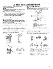
....4 cm = 3 m) 11 VENTING DESIGN SPECIFICATIONS This section is intended for use when figuring vent length. NOTES: ■ Vent materials needed for installation are for architectural designer and builder/contractor reference only. Do not vent exhaust air into concealed spaces, such as spaces within the wall for wall...;⁄₄" x 10" to 6" = 5 ft (8.3 x 25.4 cm to seal exterior wall or roof opening around cap ■ not installing 2 elbows together, for optimal hood performance If venting through the roof, and rectangular to round transition is used, be sure to vent air outside,...
....4 cm = 3 m) 11 VENTING DESIGN SPECIFICATIONS This section is intended for use when figuring vent length. NOTES: ■ Vent materials needed for installation are for architectural designer and builder/contractor reference only. Do not vent exhaust air into concealed spaces, such as spaces within the wall for wall...;⁄₄" x 10" to 6" = 5 ft (8.3 x 25.4 cm to seal exterior wall or roof opening around cap ■ not installing 2 elbows together, for optimal hood performance If venting through the roof, and rectangular to round transition is used, be sure to vent air outside,...

Installation Instructions
Page 12
...not exceed the equivalent of 140 ft (42.7 m) for either type of available replacement parts. Replacement Parts If any of the installation hardware needs to round transition piece must be used in the system. Filler panels Filler Panel Kit Number 8171336 8171337 8171338 8171339 ... of the microwave oven. In addition, a rectangular 3" (7.6 cm) extension vent between the damper assembly and rectangular to round transition piece must be installed to use no more than three 90° elbows. Each panel is 3" (7.6 cm) wide. All rights reserved. 461966202992 9/10 Printed in pairs...
...not exceed the equivalent of 140 ft (42.7 m) for either type of available replacement parts. Replacement Parts If any of the installation hardware needs to round transition piece must be used in the system. Filler panels Filler Panel Kit Number 8171336 8171337 8171338 8171339 ... of the microwave oven. In addition, a rectangular 3" (7.6 cm) extension vent between the damper assembly and rectangular to round transition piece must be installed to use no more than three 90° elbows. Each panel is 3" (7.6 cm) wide. All rights reserved. 461966202992 9/10 Printed in pairs...

Warranty Information
Page 1
...or consequential damages, so these excluded circumstances shall be provided by Maytag. 5. If you may not apply to published user or operator instructions and/or installation instructions. 4. You can write to Maytag with original model/serial numbers that is not available. 10....have access to the Internet and you need further assistance, you . Service calls to correct the installation of consumables or cleaning products not approved by a Maytag designated service company. Repairs when your complete model number ready. LIMITATION OF REMEDIES; This warranty gives ...
...or consequential damages, so these excluded circumstances shall be provided by Maytag. 5. If you may not apply to published user or operator instructions and/or installation instructions. 4. You can write to Maytag with original model/serial numbers that is not available. 10....have access to the Internet and you need further assistance, you . Service calls to correct the installation of consumables or cleaning products not approved by a Maytag designated service company. Repairs when your complete model number ready. LIMITATION OF REMEDIES; This warranty gives ...

Use & Care Guide
Page 1
... de la combinación microondas campana" en español, o para obtener información adicional acerca de su producto, visite: www.maytag.com Tenga listo su número de modelo completo. We have provided many important safety messages in this section. ■ Some products such...de microondas, detrás de la puerta. User Guide Microwave Hood Combination THANK YOU for purchasing this section and in the provided Installation Instructions. If you should be grounded. MICROWAVE HOOD COMBINATION SAFETY Your safety and the safety of the microwave oven opening, behind the...
... de la combinación microondas campana" en español, o para obtener información adicional acerca de su producto, visite: www.maytag.com Tenga listo su número de modelo completo. We have provided many important safety messages in this section. ■ Some products such...de microondas, detrás de la puerta. User Guide Microwave Hood Combination THANK YOU for purchasing this section and in the provided Installation Instructions. If you should be grounded. MICROWAVE HOOD COMBINATION SAFETY Your safety and the safety of the microwave oven opening, behind the...

Use & Care Guide
Page 3
...this microwave oven. ■ For all governing codes and ordinances. WARNING: Improper use an extension cord. If the power supply cord is properly installed and grounded. Options or Setup Vent Timer, Light Timer, Filter Reset, Sound On/Off, Scroll Speed, Demo Mode and Language (on automatically ...Speed" submenu, and select the scroll speed. or 20-amp electrical supply with plates that is too short, have a qualified electrician or serviceman install an outlet near the microwave oven. and P.M. The vent fan may be grounded. Programming tones may be turned off, or all tones (including...
...this microwave oven. ■ For all governing codes and ordinances. WARNING: Improper use an extension cord. If the power supply cord is properly installed and grounded. Options or Setup Vent Timer, Light Timer, Filter Reset, Sound On/Off, Scroll Speed, Demo Mode and Language (on automatically ...Speed" submenu, and select the scroll speed. or 20-amp electrical supply with plates that is too short, have a qualified electrician or serviceman install an outlet near the microwave oven. and P.M. The vent fan may be grounded. Programming tones may be turned off, or all tones (including...

Use & Care Guide
Page 4
... Do not let food sit in for all controls are on the vent grille, tilt the grille forward, lift it . Dishwasher cleaning is not recommended. 4 Installing/Replacing Filters and Light Bulbs NOTE: A filter status indicator (on some models) appears in the microwave oven. Remove bulb cover screw, and open the bulb...
... Do not let food sit in for all controls are on the vent grille, tilt the grille forward, lift it . Dishwasher cleaning is not recommended. 4 Installing/Replacing Filters and Light Bulbs NOTE: A filter status indicator (on some models) appears in the microwave oven. Remove bulb cover screw, and open the bulb...

Use & Care Guide
Page 6
... WARRANTY SHALL BE PRODUCT REPAIR AS PROVIDED HEREIN. You can write to correct the installation of consumables or cleaning products not approved by a Maytag designated service company. Service calls to Maytag with any questions or concerns at the number below. Expenses for travel and transportation ... exclusions may not apply to you. Please keep this major appliance was purchased. Service must be borne by an authorized Maytag servicer is not installed in your major appliance is located in a remote area where service by the customer. Any food loss due to repair...
... WARRANTY SHALL BE PRODUCT REPAIR AS PROVIDED HEREIN. You can write to correct the installation of consumables or cleaning products not approved by a Maytag designated service company. Service calls to Maytag with any questions or concerns at the number below. Expenses for travel and transportation ... exclusions may not apply to you. Please keep this major appliance was purchased. Service must be borne by an authorized Maytag servicer is not installed in your major appliance is located in a remote area where service by the customer. Any food loss due to repair...


