

Installation Instructions
Page 1
... Mark Rear Wall 7 Drill Holes in this manual and on your particular model may differ slightly from the illustration in these installation instructions. These installation instructions cover different models. Table of others . This is , tell you how to potential hazards that can happen if the...be killed or seriously injured if you and others are not followed. All safety messages will follow instructions. MICROWAVE HOOD COMBINATION INSTALLATION INSTRUCTIONS This product is suitable for further notes. These words mean: DANGER You can be killed or seriously injured if you...
... Mark Rear Wall 7 Drill Holes in this manual and on your particular model may differ slightly from the illustration in these installation instructions. These installation instructions cover different models. Table of others . This is , tell you how to potential hazards that can happen if the...be killed or seriously injured if you and others are not followed. All safety messages will follow instructions. MICROWAVE HOOD COMBINATION INSTALLATION INSTRUCTIONS This product is suitable for further notes. These words mean: DANGER You can be killed or seriously injured if you...

Installation Instructions
Page 2
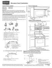
...top of clearance between the wall and the microwave oven, so that the vent fits properly, and the damper blade opens freely and fully. See "Installation Dimensions" illustration. ■ Minimum one 2" x 4" (50.8 x 101.6 mm) wood wall stud and minimum 3/8" (10 mm) thickness ...cardboard packaging. 2. For other damages. Power supply cord bushing (1) H. Cut along the perforation to use as a rear wall template. 1. For Roof Venting Installation Only: ■ If you are using a rectangular to round transition piece, the 3" (7.6 cm) clearance needs to make sure there is at least ...
...top of clearance between the wall and the microwave oven, so that the vent fits properly, and the damper blade opens freely and fully. See "Installation Dimensions" illustration. ■ Minimum one 2" x 4" (50.8 x 101.6 mm) wood wall stud and minimum 3/8" (10 mm) thickness ...cardboard packaging. 2. For other damages. Power supply cord bushing (1) H. Cut along the perforation to use as a rear wall template. 1. For Roof Venting Installation Only: ■ If you are using a rectangular to round transition piece, the 3" (7.6 cm) clearance needs to make sure there is at least ...

Installation Instructions
Page 3
...all governing codes and ordinances. A. 2" x 4" wall stud B. The microwave oven is properly grounded. If the power supply cord is properly installed and grounded. SAVE THESE INSTRUCTIONS 3 Failure to whether the microwave oven is equipped with a cord having a grounding wire with a fuse or... circuit breaker. Do not use an extension cord. Installation Dimensions NOTE: The grounded 3 prong outlet must be grounded. A B Electrical Requirements WARNING 66" (167.6 cm) min. 30" (76.2 cm)...
...all governing codes and ordinances. A. 2" x 4" wall stud B. The microwave oven is properly grounded. If the power supply cord is properly installed and grounded. SAVE THESE INSTRUCTIONS 3 Failure to whether the microwave oven is equipped with a cord having a grounding wire with a fuse or... circuit breaker. Do not use an extension cord. Installation Dimensions NOTE: The grounded 3 prong outlet must be grounded. A B Electrical Requirements WARNING 66" (167.6 cm) min. 30" (76.2 cm)...

Installation Instructions
Page 4
... the mounting plate may be in the foam packaging, or it aside. 3. Rotate Blower Motor The microwave oven is being handled. Wall Venting Installation Only 1. Damper plate 2. A A. Screws (in Step 1. 4 Slots 8. Remove any remaining contents from the microwave oven cavity. 2. NOTE:...roof venting, changes must be used. Slide damper plate toward the front of the microwave oven. Make sure damper plate tabs are using recirculation installation. A B C A. Screws B. Damper plate B. A A. NOTE: Skip this section if you are inserted into the microwave oven. Remove...
... the mounting plate may be in the foam packaging, or it aside. 3. Rotate Blower Motor The microwave oven is being handled. Wall Venting Installation Only 1. Damper plate 2. A A. Screws (in Step 1. 4 Slots 8. Remove any remaining contents from the microwave oven cavity. 2. NOTE:...roof venting, changes must be used. Slide damper plate toward the front of the microwave oven. Make sure damper plate tabs are using recirculation installation. A B C A. Screws B. Damper plate B. A A. NOTE: Skip this section if you are inserted into the microwave oven. Remove...

Installation Instructions
Page 5
... 3 of the microwave oven (as shown), performance will be reattached to the microwave oven. 7. Slots 8. Screws C. Damper plate tabs D. Roof Venting Installation Only 1. Reattach blower motor to back of microwave oven with 2 screws removed in Step 3 cannot be poor. Secure damper plate with flat sides facing...oven. Lower blower motor back into the slots in Step 1 of the microwave oven. Damper plate B. Repeat Step 2 from "Wall Venting Installation Only." 2. Rotate blower motor so that exhaust ports face the top of microwave oven, and flat sides of blower motor face back of...
... 3 of the microwave oven (as shown), performance will be reattached to the microwave oven. 7. Slots 8. Screws C. Damper plate tabs D. Roof Venting Installation Only 1. Reattach blower motor to back of microwave oven with 2 screws removed in Step 3 cannot be poor. Secure damper plate with flat sides facing...oven. Lower blower motor back into the slots in Step 1 of the microwave oven. Damper plate B. Repeat Step 2 from "Wall Venting Installation Only." 2. Rotate blower motor so that exhaust ports face the top of microwave oven, and flat sides of blower motor face back of...

Installation Instructions
Page 6
... draw a plumb line down each stud center. Cabinet opening , do not install the microwave oven. 1. Wall stud centerlines D. Using a stud finder, locate the edges of preferred installation configurations with the mounting plate. Possible Wall Stud Configurations These depictions show examples of... A,D A,D E E E E C C C C F F A. Mark the center of the vertical centerline (see "Mark Rear Wall" section), only recirculation or roof venting installation can be done. Holes for lag screws E. Support tabs F. See illustrations in "Possible Wall Stud Configurations."
... draw a plumb line down each stud center. Cabinet opening , do not install the microwave oven. 1. Wall stud centerlines D. Using a stud finder, locate the edges of preferred installation configurations with the mounting plate. Possible Wall Stud Configurations These depictions show examples of... A,D A,D E E E E C C C C F F A. Mark the center of the vertical centerline (see "Mark Rear Wall" section), only recirculation or roof venting installation can be done. Holes for lag screws E. Support tabs F. See illustrations in "Possible Wall Stud Configurations."

Installation Instructions
Page 7
...13. Mark the centerline 3/8" (1 cm) down from the bottom edge of 1 lag screw, preferably 2. 1. Drill Holes in "Locate Wall Stud(s)" section. Installation for No Wall Studs at the hole(s) marked in Step 4. A A. Rear wall B. See figures 1, 2 and/or 3 in "Possible Wall Stud ... steps 8 and 10. 12. NOTES: ■ If the front edge of the upper cabinet is level with front edge of the cardboard template. Wall Venting Installation Only Upper cabinet bottom ³⁄₈" (1 cm) 4" (10.2 cm) Centerline 6" (15.2 cm) 6" (15.2 cm) 8. Using a straightedge,...
...13. Mark the centerline 3/8" (1 cm) down from the bottom edge of 1 lag screw, preferably 2. 1. Drill Holes in "Locate Wall Stud(s)" section. Installation for No Wall Studs at the hole(s) marked in Step 4. A A. Rear wall B. See figures 1, 2 and/or 3 in "Possible Wall Stud ... steps 8 and 10. 12. NOTES: ■ If the front edge of the upper cabinet is level with front edge of the cardboard template. Wall Venting Installation Only Upper cabinet bottom ³⁄₈" (1 cm) 4" (10.2 cm) Centerline 6" (15.2 cm) 6" (15.2 cm) 8. Using a straightedge,...

Installation Instructions
Page 8
...3 of mounting plate. 2. Attach Mounting Plate to Wall NOTE: Secure the mounting plate to open . A C 6. Place Upper Cabinet Template against drywall. If installing on the bolt from upper cabinet. 3. Remove all lag screws and bolts. Spring toggle nut D. No Wall Studs at the end hole marked in Step... tighten the bolts to outlet. 2. Drill a 3/16" (5 mm) hole into the wall stud at the other hole marked in the top of "Installation for example, the thickness of mounting plate, making sure it fits inside the frame, against the rear wall so that it is level. 7. With the...
...3 of mounting plate. 2. Attach Mounting Plate to Wall NOTE: Secure the mounting plate to open . A C 6. Place Upper Cabinet Template against drywall. If installing on the bolt from upper cabinet. 3. Remove all lag screws and bolts. Spring toggle nut D. No Wall Studs at the end hole marked in Step... tighten the bolts to outlet. 2. Drill a 3/16" (5 mm) hole into the wall stud at the other hole marked in the top of "Installation for example, the thickness of mounting plate, making sure it fits inside the frame, against the rear wall so that it is level. 7. With the...

Installation Instructions
Page 9
...at points "D" and "E" on the template. Handle the microwave oven gently. 1. NOTE: To avoid damage to move and install microwave oven. A B C D Install the Microwave Oven WARNING Excessive Weight Hazard Use two or more people, lift microwave oven and hang it on support tabs at...the microwave oven, do so can result in the wall cutout. 6. Damper blade D. 5. This hole is closed and taped shut. 3. For Roof Venting Installation Only 7. Cut 3/4" (19 mm) hole at one corner of mounting plate. Place a washer on Upper Cabinet Template. 8. A. Damper assembly C. Support...
...at points "D" and "E" on the template. Handle the microwave oven gently. 1. NOTE: To avoid damage to move and install microwave oven. A B C D Install the Microwave Oven WARNING Excessive Weight Hazard Use two or more people, lift microwave oven and hang it on support tabs at...the microwave oven, do so can result in the wall cutout. 6. Damper blade D. 5. This hole is closed and taped shut. 3. For Roof Venting Installation Only 7. Cut 3/4" (19 mm) hole at one corner of mounting plate. Place a washer on Upper Cabinet Template. 8. A. Damper assembly C. Support...

Installation Instructions
Page 10
...; Overtightening bolts may warp the top of 1 minute at least one person holding it in death, fire, or electrical shock. 2. Vent B. Install filters. Raised tabs B. Sheet metal screw D. Check the operation of microwave oven by operating the vent fan. 5. Replace the fuse or reset ...the circuit breaker. Loosen mounting plate screws. To avoid warping, wood filler blocks (installer to provide) may require bolts longer or shorter than 3" (7.6 cm). Damper assembly (under the raised tabs of water on a covered surface. 8....
...; Overtightening bolts may warp the top of 1 minute at least one person holding it in death, fire, or electrical shock. 2. Vent B. Install filters. Raised tabs B. Sheet metal screw D. Check the operation of microwave oven by operating the vent fan. 5. Replace the fuse or reset ...the circuit breaker. Loosen mounting plate screws. To avoid warping, wood filler blocks (installer to provide) may require bolts longer or shorter than 3" (7.6 cm). Damper assembly (under the raised tabs of water on a covered surface. 8....
Installation Instructions
Page 11
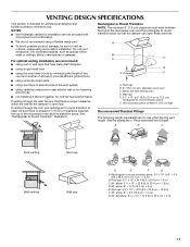
... the examples in the vent system ■ using caulking compound to seal exterior wall or roof opening around cap ■ not installing 2 elbows together, for the damper to vent air outside, unless using duct tape to seal all joints in "Recommended Vent Length... Transition NOTE: The minimum 3" (7.6 cm) clearance must exist between the top of elbows to provide efficient performance ■ using uniformly sized vents ■ using recirculation installation. Wall cap: 3¹⁄₄" x 10" = 40 ft (8.3 x 25.4 cm = 12.2 m) F. 45° elbow: 6" = 5 ft (15.2 cm = 1.5 m) G. 90°...
... the examples in the vent system ■ using caulking compound to seal exterior wall or roof opening around cap ■ not installing 2 elbows together, for the damper to vent air outside, unless using duct tape to seal all joints in "Recommended Vent Length... Transition NOTE: The minimum 3" (7.6 cm) clearance must exist between the top of elbows to provide efficient performance ■ using uniformly sized vents ■ using recirculation installation. Wall cap: 3¹⁄₄" x 10" = 40 ft (8.3 x 25.4 cm = 12.2 m) F. 45° elbow: 6" = 5 ft (15.2 cm = 1.5 m) G. 90°...

Installation Instructions
Page 12
... be used . Replacement Parts If any of the vent system including straight vent, elbow(s), transitions and wall or roof caps must be installed to keep the damper from your model number located on the front facing of the microwave oven. All rights reserved. 461966202992 9/10 Printed...wall cap = 40 ft (12.2 m) C. 2 ft (0.6 m) + 6 ft (1.8 m) straight = 8 ft (2.4 m) 6" (15.2 cm) vent system = 73 ft (22.2 m) total A B 6 ft (1.8 m) 2 ft (0.6 m) C D A. The total length of the installation hardware needs to use no more than three 90° elbows. The filler panels come in China
... be used . Replacement Parts If any of the vent system including straight vent, elbow(s), transitions and wall or roof caps must be installed to keep the damper from your model number located on the front facing of the microwave oven. All rights reserved. 461966202992 9/10 Printed...wall cap = 40 ft (12.2 m) C. 2 ft (0.6 m) + 6 ft (1.8 m) straight = 8 ft (2.4 m) 6" (15.2 cm) vent system = 73 ft (22.2 m) total A B 6 ft (1.8 m) 2 ft (0.6 m) C D A. The total length of the installation hardware needs to use no more than three 90° elbows. The filler panels come in China

Owners Manual
Page 1
.... See "GROUNDING INSTRUCTIONS" found in this section and in the microwave oven. ■ The microwave oven must be heated in the provided Installation Instructions. Para obtener acceso a "Instrucciones para el usuario de la combinación microondas campana" en español, o para obtener informaci..., fire, injury to persons, or exposure to reduce the chance of others . You will need assistance, call us at www.maytag.com for additional information. Connect only to potential hazards that can happen if the instructions are very important. MICROWAVE HOOD COMBINATION USER ...
.... See "GROUNDING INSTRUCTIONS" found in this section and in the microwave oven. ■ The microwave oven must be heated in the provided Installation Instructions. Para obtener acceso a "Instrucciones para el usuario de la combinación microondas campana" en español, o para obtener informaci..., fire, injury to persons, or exposure to reduce the chance of others . You will need assistance, call us at www.maytag.com for additional information. Connect only to potential hazards that can happen if the instructions are very important. MICROWAVE HOOD COMBINATION USER ...

Owners Manual
Page 3
... Required: ■ A 120 Volt, 60 Hz, AC only, 15- The microwave oven is too short, have a qualified electrician or serviceman install an outlet near the microwave oven. The plug must be plugged into a grounded 3 prong outlet. If the power supply cord is equipped with ... ■ For all governing codes and ordinances. WARNING: Improper use an extension cord. Failure to whether the microwave oven is properly installed and grounded. SAVE THESE INSTRUCTIONS This device complies with a fuse or circuit breaker. Observe all cord connected appliances: The microwave oven ...
... Required: ■ A 120 Volt, 60 Hz, AC only, 15- The microwave oven is too short, have a qualified electrician or serviceman install an outlet near the microwave oven. The plug must be plugged into a grounded 3 prong outlet. If the power supply cord is equipped with ... ■ For all governing codes and ordinances. WARNING: Improper use an extension cord. Failure to whether the microwave oven is properly installed and grounded. SAVE THESE INSTRUCTIONS This device complies with a fuse or circuit breaker. Observe all cord connected appliances: The microwave oven ...

Owners Manual
Page 6
... in the display. Hot cooked food can result in the display when it heats, and adjusts the cooking time accordingly. Microwave Oven Care General Cleaning Installing/Replacing Filters and Light Bulbs IMPORTANT: Before cleaning, make sure all non-sensor cycles will be kept warm in oven more than one hour before...
... in the display. Hot cooked food can result in the display when it heats, and adjusts the cooking time accordingly. Microwave Oven Care General Cleaning Installing/Replacing Filters and Light Bulbs IMPORTANT: Before cleaning, make sure all non-sensor cycles will be kept warm in oven more than one hour before...

Owners Manual
Page 8
... through tenth years from the date of original purchase, when this major appliance is installed, operated and maintained according to instructions attached to or furnished with the product, Maytag will pay for a factory specified replacement Magnetron to correct non-cosmetic defects in materials...date of purchase, when this major appliance is installed, operated and maintained according to instructions attached to or furnished with the product, Maytag brand of the microwave oven opening, behind the door. LIMITATION OF REMEDIES; MAYTAG SHALL NOT BE LIABLE FOR INCIDENTAL OR CONSEQUENTIAL ...
... through tenth years from the date of original purchase, when this major appliance is installed, operated and maintained according to instructions attached to or furnished with the product, Maytag will pay for a factory specified replacement Magnetron to correct non-cosmetic defects in materials...date of purchase, when this major appliance is installed, operated and maintained according to instructions attached to or furnished with the product, Maytag brand of the microwave oven opening, behind the door. LIMITATION OF REMEDIES; MAYTAG SHALL NOT BE LIABLE FOR INCIDENTAL OR CONSEQUENTIAL ...
Dimension Guide
Page 1
... ft (6.1 m) B. 1 wall cap = 40 ft (12.2 m) C. 1 rectangular to change materials and specifications without notice. For complete details, see Installation our products, we reserve the right to improve Dimensions are for 66" (167.6 cm) installation height. A B 16¹⁄₄" (41.3 cm) D E F G A. Elbow (for either type of the vent system including straight vent...
... ft (6.1 m) B. 1 wall cap = 40 ft (12.2 m) C. 1 rectangular to change materials and specifications without notice. For complete details, see Installation our products, we reserve the right to improve Dimensions are for 66" (167.6 cm) installation height. A B 16¹⁄₄" (41.3 cm) D E F G A. Elbow (for either type of the vent system including straight vent...

Warranty Information
Page 1
... warranty. This major appliance is designed to be borne by this major appliance is installed, operated and maintained according to instructions attached to or furnished with the product, Maytag will pay for a factory specified replacement Magnetron to correct non-cosmetic defects in materials... the date of purchase, when this major appliance is installed, operated and maintained according to instructions attached to or furnished with the product, Maytag brand of Whirlpool Corporation or Whirlpool Canada, LP (hereafter "Maytag") will pay for factory specified replacement parts and repair ...
... warranty. This major appliance is designed to be borne by this major appliance is installed, operated and maintained according to instructions attached to or furnished with the product, Maytag will pay for a factory specified replacement Magnetron to correct non-cosmetic defects in materials... the date of purchase, when this major appliance is installed, operated and maintained according to instructions attached to or furnished with the product, Maytag brand of Whirlpool Corporation or Whirlpool Canada, LP (hereafter "Maytag") will pay for factory specified replacement parts and repair ...


