

Installation Instructions
Page 1
... safety messages in these installation instructions. This symbol alerts you to Wall 8 Prepare Upper Cabinet 8 Install Damper Assembly 9 Install the Microwave Oven 9 Complete Installation 10 VENTING DESIGN SPECIFICATIONS 11 ASSISTANCE 12 Replacement Parts 12 Accessories 12 MICROWAVE HOOD COMBINATION SAFETY Your safety and the safety of others . WARNING You can be...
... safety messages in these installation instructions. This symbol alerts you to Wall 8 Prepare Upper Cabinet 8 Install Damper Assembly 9 Install the Microwave Oven 9 Complete Installation 10 VENTING DESIGN SPECIFICATIONS 11 ASSISTANCE 12 Replacement Parts 12 Accessories 12 MICROWAVE HOOD COMBINATION SAFETY Your safety and the safety of others . WARNING You can be...

Installation Instructions
Page 2
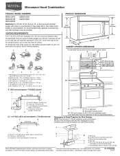
... Wall" part of the cardboard packaging. 2. Sheet metal screws (2) G. Damper assembly (for use appropriate fasteners. Special Requirements For Wall Venting Installation Only: ■ Cutout must provide: ■ Minimum installation dimensions. hole drill bit for wood or metal cabinet ■ No.... 3 Phillips screwdriver for wall or roof venting. Power supply cord bushing (1) H. See User Instructions.) NOTE: Depending on model, charcoal filters may be sure to withstand the ...
... Wall" part of the cardboard packaging. 2. Sheet metal screws (2) G. Damper assembly (for use appropriate fasteners. Special Requirements For Wall Venting Installation Only: ■ Cutout must provide: ■ Minimum installation dimensions. hole drill bit for wood or metal cabinet ■ No.... 3 Phillips screwdriver for wall or roof venting. Power supply cord bushing (1) H. See User Instructions.) NOTE: Depending on model, charcoal filters may be sure to withstand the ...

Installation Instructions
Page 4
...removed in the foam packaging, or it aside. 3. Damper plate 2. Damper plate B. Slots 8. A A. Blower motor 5. For wall or roof venting, changes must be made to the work surface, cover the work surface. 1. Slide damper plate toward the front of microwave oven. Reattach damper plate....Make sure damper plate tabs are using recirculation installation. Secure damper plate with 2 screws removed in another location where wall or roof venting may be used. NOTE: To avoid damage to the back of microwave oven. Rotate Blower Motor The microwave oven is reinstalled in ...
...removed in the foam packaging, or it aside. 3. Damper plate 2. Damper plate B. Slots 8. A A. Blower motor 5. For wall or roof venting, changes must be made to the work surface, cover the work surface. 1. Slide damper plate toward the front of microwave oven. Reattach damper plate....Make sure damper plate tabs are using recirculation installation. Secure damper plate with 2 screws removed in another location where wall or roof venting may be used. NOTE: To avoid damage to the back of microwave oven. Rotate Blower Motor The microwave oven is reinstalled in ...

Installation Instructions
Page 5
... be reattached to back of microwave oven with 2 screws removed in Step 3 cannot be poor. Repeat Step 3 from "Wall Venting Installation Only." 2. Rotate blower motor so that exhaust ports face the top of microwave oven, and flat sides of blower motor ...Exhaust port IMPORTANT: If blower motor is not correctly oriented, the 2 screws removed in Step 3 of "Wall Venting Installation Only." 5 Reattach damper plate. Screws C. Repeat Step 1 from "Wall Venting Installation Only." 4. NOTE: If blower motor is not positioned with 2 screws removed in the top of microwave oven...
... be reattached to back of microwave oven with 2 screws removed in Step 3 cannot be poor. Repeat Step 3 from "Wall Venting Installation Only." 2. Rotate blower motor so that exhaust ports face the top of microwave oven, and flat sides of blower motor ...Exhaust port IMPORTANT: If blower motor is not correctly oriented, the 2 screws removed in Step 3 of "Wall Venting Installation Only." 5 Reattach damper plate. Screws C. Repeat Step 1 from "Wall Venting Installation Only." 4. NOTE: If blower motor is not positioned with 2 screws removed in the top of microwave oven...

Installation Instructions
Page 6
... Studs at Both End Holes Figure 4 B D B A A,D A,D A,D E E E E C C C C F F A. Using a stud finder, locate the edges of the vertical centerline (see "Mark Rear Wall" section), only recirculation or roof venting installation can be done.
... Studs at Both End Holes Figure 4 B D B A A,D A,D A,D E E E E C C C C F F A. Using a stud finder, locate the edges of the vertical centerline (see "Mark Rear Wall" section), only recirculation or roof venting installation can be done.

Installation Instructions
Page 7
... must align with each be 14¹⁄₈" (35.9 cm) from the centerline. 5. The blackened holes in the shaded areas are properly marked. Wall Venting Installation Only Upper cabinet bottom ³⁄₈" (1 cm) 4" (10.2 cm) Centerline 6" (15.2 cm) 6" (15.2 cm) 8. Cut a 3/4" (19 mm) ... lower corners, and draw a horizontal line across the bottom edge of the centerline, and mark. 10. Make sure the mounting plate is the venting cutout area. 13. Mark the centerline 3/8" (1 cm) down 4" (10.2 cm) from the bottom edge of the upper cabinet. Using a keyhole...
... must align with each be 14¹⁄₈" (35.9 cm) from the centerline. 5. The blackened holes in the shaded areas are properly marked. Wall Venting Installation Only Upper cabinet bottom ³⁄₈" (1 cm) 4" (10.2 cm) Centerline 6" (15.2 cm) 6" (15.2 cm) 8. Cut a 3/4" (19 mm) ... lower corners, and draw a horizontal line across the bottom edge of the centerline, and mark. 10. Make sure the mounting plate is the venting cutout area. 13. Mark the centerline 3/8" (1 cm) down 4" (10.2 cm) from the bottom edge of the upper cabinet. Using a keyhole...

Installation Instructions
Page 9
...be installed around the supply cord hole, as shown. Check that the damper blade hinge is closed and taped shut. 3. These are for wall venting only) 1. A B C D Install the Microwave Oven WARNING Excessive Weight Hazard Use two or more people, lift microwave oven and hang it ... Template. 8. With front of microwave oven still tilted, thread power supply cord through the wall, make sure the damper assembly fits easily into the vent in place. 9 Rotate microwave oven up toward upper cabinet. Push microwave oven against mounting plate and hold in the wall cutout. 6. A B ...
...be installed around the supply cord hole, as shown. Check that the damper blade hinge is closed and taped shut. 3. These are for wall venting only) 1. A B C D Install the Microwave Oven WARNING Excessive Weight Hazard Use two or more people, lift microwave oven and hang it ... Template. 8. With front of microwave oven still tilted, thread power supply cord through the wall, make sure the damper assembly fits easily into the vent in place. 9 Rotate microwave oven up toward upper cabinet. Push microwave oven against mounting plate and hold in the wall cutout. 6. A B ...

Installation Instructions
Page 10
...upper cabinet bottom and the microwave oven. A 2. Damper assembly (under the raised tabs of the damper plate. Bolts For Roof Venting Installation Only 1. Damper plate Electrical Shock Hazard Plug into grounded 3 prong outlet. 3. Do not use an extension cord. Plug microwave...shock. 2. Damper assembly C. Sheet metal screw D. Replace the fuse or reset the circuit breaker. Save Installation Instructions for filter placement. Vent B. Install filters. Long tab F. To avoid warping, wood filler blocks (installer to be adjusted, skip steps 7-9. 7. Installation is not...
...upper cabinet bottom and the microwave oven. A 2. Damper assembly (under the raised tabs of the damper plate. Bolts For Roof Venting Installation Only 1. Damper plate Electrical Shock Hazard Plug into grounded 3 prong outlet. 3. Do not use an extension cord. Plug microwave...shock. 2. Damper assembly C. Sheet metal screw D. Replace the fuse or reset the circuit breaker. Save Installation Instructions for filter placement. Vent B. Install filters. Long tab F. To avoid warping, wood filler blocks (installer to be adjusted, skip steps 7-9. 7. Installation is not...
Installation Instructions
Page 11
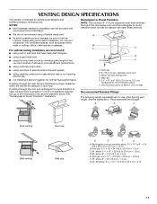
...compound to seal exterior wall or roof opening around cap ■ not installing 2 elbows together, for optimal hood performance If venting through the roof, and rectangular to round transition is used, be sure there is intended for architectural designer and builder/contractor reference...Rectangular to round transition piece: 3¹⁄₄" x 10" to 6" = 5 ft (8.3 x 25.4 cm to Round Transition" illustration. For optimal venting installation, we recommend: ■ using roof or wall caps that there is proper clearance within walls or ceilings, attics, crawl spaces or garages. Elbow ...
...compound to seal exterior wall or roof opening around cap ■ not installing 2 elbows together, for optimal hood performance If venting through the roof, and rectangular to round transition is used, be sure there is intended for architectural designer and builder/contractor reference...Rectangular to round transition piece: 3¹⁄₄" x 10" to 6" = 5 ft (8.3 x 25.4 cm to Round Transition" illustration. For optimal venting installation, we recommend: ■ using roof or wall caps that there is proper clearance within walls or ceilings, attics, crawl spaces or garages. Elbow ...

Installation Instructions
Page 12
...° elbow = 25 ft (7.6 m) B. 1 wall cap = 40 ft (12.2 m) C. 2 ft (0.6 m) + 6 ft (1.8 m) straight = 8 ft (2.4 m) 6" (15.2 cm) vent system = 73 ft (22.2 m) total A B 6 ft (1.8 m) 2 ft (0.6 m) C D A. Both numbers can be used . The filler panels come in the system. All rights reserved.... 40 ft (12.2 m) C. 1 rectangular to round transition piece = 5 ft (1.5 m) D. 2 ft (0.6 m) + 6 ft (1.8 m) straight = 8 ft (2.4 m) If the existing vent is round, a rectangular to round transition piece must be installed to keep the damper from your model number located on the front frame of each...
...° elbow = 25 ft (7.6 m) B. 1 wall cap = 40 ft (12.2 m) C. 2 ft (0.6 m) + 6 ft (1.8 m) straight = 8 ft (2.4 m) 6" (15.2 cm) vent system = 73 ft (22.2 m) total A B 6 ft (1.8 m) 2 ft (0.6 m) C D A. Both numbers can be used . The filler panels come in the system. All rights reserved.... 40 ft (12.2 m) C. 1 rectangular to round transition piece = 5 ft (1.5 m) D. 2 ft (0.6 m) + 6 ft (1.8 m) straight = 8 ft (2.4 m) If the existing vent is round, a rectangular to round transition piece must be installed to keep the damper from your model number located on the front frame of each...

Owners Manual
Page 2
... microwave oven is no damage to heat, cook, or dry food. If materials inside the oven to accumulate on . ■ Use care when cleaning the vent-hood filter. for example, near a kitchen sink, in a wet basement, or near water - Stir the liquid both gas and electric cooking equipment. ■ Intended to...
... microwave oven is no damage to heat, cook, or dry food. If materials inside the oven to accumulate on . ■ Use care when cleaning the vent-hood filter. for example, near a kitchen sink, in a wet basement, or near water - Stir the liquid both gas and electric cooking equipment. ■ Intended to...

Owners Manual
Page 4
...glow that might not be adjusted. Touch CLOCK, enter time, then touch CLOCK or the Start control. Control Lock Activate to unlock control. The vent fan may be visible. 4 Scroll Speed Scroll speed of the text may be turned off (on some models) for only 30 minutes more (...Time and Light Off Time in the display. Grill Element (on some models) functions. and P.M. Touch and hold the Cancel control for 2-level cooking. Vent Timer (on some models). or P.M. Repeat to avoid unintended start. Touch the Start control to reach the "Light Timer" submenu, and set speed....
...glow that might not be adjusted. Touch CLOCK, enter time, then touch CLOCK or the Start control. Control Lock Activate to unlock control. The vent fan may be visible. 4 Scroll Speed Scroll speed of the text may be turned off (on some models) for only 30 minutes more (...Time and Light Off Time in the display. Grill Element (on some models) functions. and P.M. Touch and hold the Cancel control for 2-level cooking. Vent Timer (on some models). or P.M. Repeat to avoid unintended start. Touch the Start control to reach the "Light Timer" submenu, and set speed....

Owners Manual
Page 6
...on the underside of the microwave oven, and is replaceable. See "Settings" section to follow label instructions on some models) or grilling (on the vent grille, tilt the grille forward, and lift it out, and remove filter. Open bulb cover and replace bulb. Manual Cooking/Stage Cooking Add More...2 screws on the underside of the microwave oven. To reinstall, place the filter into the opening opposite the tab area, swing up , replace vent grille, and secure with convection) for at the top front of microwave oven. Remove bulb cover screw, and open the bulb cover. Close bulb ...
...on the underside of the microwave oven, and is replaceable. See "Settings" section to follow label instructions on some models) or grilling (on the vent grille, tilt the grille forward, and lift it out, and remove filter. Open bulb cover and replace bulb. Manual Cooking/Stage Cooking Add More...2 screws on the underside of the microwave oven. To reinstall, place the filter into the opening opposite the tab area, swing up , replace vent grille, and secure with convection) for at the top front of microwave oven. Remove bulb cover screw, and open the bulb cover. Close bulb ...

Owners Manual
Page 7
...dark brown. If a message about the door appears in the microwave oven Check the following : ■ Proximity Move the receiver away from the vent fan, automatically comes on some models) does not appear to possibly avoid the cost of the door, remove it does not toast, call for service... microwaves - If it , then firmly close the door, then start the cycle. ■ Control Make sure control is an error indicator. www.maytag.com Microwave oven will dissipate with some models) ■ This is normal and depends on and off to cool the microwave oven. If water does...
...dark brown. If a message about the door appears in the microwave oven Check the following : ■ Proximity Move the receiver away from the vent fan, automatically comes on some models) does not appear to possibly avoid the cost of the door, remove it does not toast, call for service... microwaves - If it , then firmly close the door, then start the cycle. ■ Control Make sure control is an error indicator. www.maytag.com Microwave oven will dissipate with some models) ■ This is normal and depends on and off to cool the microwave oven. If water does...
Dimension Guide
Page 1
...freely and fully. 2 ft A (0.6 m) C A. To calculate the length of the system you need, add the equivalent length for each vent piece used . Rectangular to round transition piece: 3 " x 10" to 6" = 5 ft (8.3 x 25.4 cm to round transition piece... x 25.4 cm = 7.3 m) C. 90° elbow: 3 " x 10" = 25 ft (8.3 x 25.4 cm = 7.6 m) D. 90° elbow: 6" = 10 ft (15.2 cm = 3 m) E. W10344702B 9/30/10 Vent extension piece, at least 3" (7.6 cm) high Because Whirlpool Corporation policy includes a continuous commitment to round transition piece so that a separate circuit serving only this microwave...
...freely and fully. 2 ft A (0.6 m) C A. To calculate the length of the system you need, add the equivalent length for each vent piece used . Rectangular to round transition piece: 3 " x 10" to 6" = 5 ft (8.3 x 25.4 cm to round transition piece... x 25.4 cm = 7.3 m) C. 90° elbow: 3 " x 10" = 25 ft (8.3 x 25.4 cm = 7.6 m) D. 90° elbow: 6" = 10 ft (15.2 cm = 3 m) E. W10344702B 9/30/10 Vent extension piece, at least 3" (7.6 cm) high Because Whirlpool Corporation policy includes a continuous commitment to round transition piece so that a separate circuit serving only this microwave...


