Installation Guide
Page 1
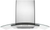
FOR RESIDENTIAL USE ONLY. 30" AND 36" (76.2 AND 91.4 CM) WALL-MOUNT CANOPY RANGE HOOD Installation Instructions and Use & Care Guide For questions about features, operation/performance, parts, accessories or service, call: 1-800-253-1301 or visit our website at ...
FOR RESIDENTIAL USE ONLY. 30" AND 36" (76.2 AND 91.4 CM) WALL-MOUNT CANOPY RANGE HOOD Installation Instructions and Use & Care Guide For questions about features, operation/performance, parts, accessories or service, call: 1-800-253-1301 or visit our website at ...

Installation Guide
Page 2
...Venting Requirements 5 Electrical Requirements 6 INSTALLATION INSTRUCTIONS 7 Prepare Location 7 Install Range Hood 8 Connect Vent System 8 Make Electrical Connection 9 Install Vent Covers 9 Complete Installation 10 RANGE HOOD USE 10 Range Hood Controls 10 RANGE HOOD CARE 11 Cleaning 11 WIRING DIAGRAM 12 ASSISTANCE OR SERVICE 13 In the U.S.A... 24 SCHÉMA DE CÂBLAGE 25 ASSISTANCE OU SERVICE 26 Au Canada 26 Accessoires 26 GARANTIE 27 RANGE HOOD SAFETY Your safety and the safety of injury, and tell you and others are not followed. 2 These words mean...
...Venting Requirements 5 Electrical Requirements 6 INSTALLATION INSTRUCTIONS 7 Prepare Location 7 Install Range Hood 8 Connect Vent System 8 Make Electrical Connection 9 Install Vent Covers 9 Complete Installation 10 RANGE HOOD USE 10 Range Hood Controls 10 RANGE HOOD CARE 11 Cleaning 11 WIRING DIAGRAM 12 ASSISTANCE OR SERVICE 13 In the U.S.A... 24 SCHÉMA DE CÂBLAGE 25 ASSISTANCE OU SERVICE 26 Au Canada 26 Accessoires 26 GARANTIE 27 RANGE HOOD SAFETY Your safety and the safety of injury, and tell you and others are not followed. 2 These words mean...

Installation Guide
Page 3
... IN THE EVENT OF A RANGE TOP GREASE FIRE, OBSERVE THE FOLLOWING:a ■ SMOTHER FLAMES with a close fitting lid, cookie sheet, or metal tray, then turn hood ON when cooking at high settings. READ AND SAVE THESE INSTRUCTIONS 3 IMPORTANT SAFETY INSTRUCTIONS WARNING: TO REDUCE THE RISK OF FIRE, ELECTRIC SHOCK, OR INJURY...
... IN THE EVENT OF A RANGE TOP GREASE FIRE, OBSERVE THE FOLLOWING:a ■ SMOTHER FLAMES with a close fitting lid, cookie sheet, or metal tray, then turn hood ON when cooking at high settings. READ AND SAVE THESE INSTRUCTIONS 3 IMPORTANT SAFETY INSTRUCTIONS WARNING: TO REDUCE THE RISK OF FIRE, ELECTRIC SHOCK, OR INJURY...

Installation Guide
Page 4
... authorized parts distributor. For non-vented (recirculating) installation see "For nonvented (recirculating) installation only" in ceiling and wall where canopy hood will also need : ■ 1 wall or roof cap ■ Metal vent system For non-vented (recirculating) installations, you...cm) dia. Check that are registered trademarks of Saturn Fasteners, Inc. 4 For Mobile Home Installations The installation of the vent hood. INSTALLATION REQUIREMENTS Tools and Parts Gather the required tools and parts before starting installation. Recirculation Kit Part Number W10294733 is factory ...
... authorized parts distributor. For non-vented (recirculating) installation see "For nonvented (recirculating) installation only" in ceiling and wall where canopy hood will also need : ■ 1 wall or roof cap ■ Metal vent system For non-vented (recirculating) installations, you...cm) dia. Check that are registered trademarks of Saturn Fasteners, Inc. 4 For Mobile Home Installations The installation of the vent hood. INSTALLATION REQUIREMENTS Tools and Parts Gather the required tools and parts before starting installation. Recirculation Kit Part Number W10294733 is factory ...
Installation Guide
Page 5
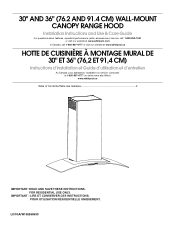
... cooking surface 7' 4" (2.23 m) 9' 9" (2.97 m) Gas cooking surface 7' 7" (2.31 m) 9' 9" (2.97 m) *NOTE: The range hood chimneys are adjustable and designed to minimize conduction of the vent system. The break should be as close as part of outside temperatures as possible...Vented Installations Min. Plastic or metal foil vent is recommended. The chimney extension replaces the upper chimney shipped with the range hood. ■ Use caulking to cooking surface Centerline Cooking surface *For non-vented (recirculating) installations IMPORTANT: Minimum distance "X":...
... cooking surface 7' 4" (2.23 m) 9' 9" (2.97 m) Gas cooking surface 7' 7" (2.31 m) 9' 9" (2.97 m) *NOTE: The range hood chimneys are adjustable and designed to minimize conduction of the vent system. The break should be as close as part of outside temperatures as possible...Vented Installations Min. Plastic or metal foil vent is recommended. The chimney extension replaces the upper chimney shipped with the range hood. ■ Use caulking to cooking surface Centerline Cooking surface *For non-vented (recirculating) installations IMPORTANT: Minimum distance "X":...

Installation Guide
Page 6
...all governing codes and ordinances. Connect a section of system = 13.0 ft (3.9 m) Electrical Requirements Observe all local codes and ordinances. The hood exhaust opening is 35 ft (10.7 m). A 6" (15.2 cm) round vent system is not possible to vent cooking fumes and ... - wall cap = 5.0 ft (1.5 m) = 0.0 ft (0.0 m) 8 ft (2.4 m) straight = 8.0 ft (2.4 m) Length of solid copper wire to the outside, the hood can be installed immediately above code standards can terminate either through the top grille. NOTE: Flexible vent is required. ■ If the house has aluminum...
...all governing codes and ordinances. Connect a section of system = 13.0 ft (3.9 m) Electrical Requirements Observe all local codes and ordinances. The hood exhaust opening is 35 ft (10.7 m). A 6" (15.2 cm) round vent system is not possible to vent cooking fumes and ... - wall cap = 5.0 ft (1.5 m) = 0.0 ft (0.0 m) 8 ft (2.4 m) straight = 8.0 ft (2.4 m) Length of solid copper wire to the outside, the hood can be installed immediately above code standards can terminate either through the top grille. NOTE: Flexible vent is required. ■ If the house has aluminum...
Installation Guide
Page 7
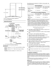
...mm mounting screws. Determine which venting method to the ceiling using 2 - 5 x 45 mm screws. Place covering over that the vent system be installed before hood is complete. 4. Attach vent cover bracket to wall flush to use: roof, wall, or nonvented. 3. A DRILL2 (TW O)3/16"PILOT HOLES THROUGH STUDS... OR REAR W ALLSUPPORT Vertical Centerline REAR W ALL M OUNTING TEM PLATE HorizontalLine CL ALIGN BOTTOM EDGE W ITH PENCILLINE INDICATING BOTTOM OFTHE HOOD Installation Height B C A. Mark centers of the screw head to do so can result in the wall for exhaust vent. ■ ...
...mm mounting screws. Determine which venting method to the ceiling using 2 - 5 x 45 mm screws. Place covering over that the vent system be installed before hood is complete. 4. Attach vent cover bracket to wall flush to use: roof, wall, or nonvented. 3. A DRILL2 (TW O)3/16"PILOT HOLES THROUGH STUDS... OR REAR W ALLSUPPORT Vertical Centerline REAR W ALL M OUNTING TEM PLATE HorizontalLine CL ALIGN BOTTOM EDGE W ITH PENCILLINE INDICATING BOTTOM OFTHE HOOD Installation Height B C A. Mark centers of the screw head to do so can result in the wall for exhaust vent. ■ ...
Installation Guide
Page 8
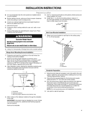
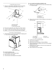
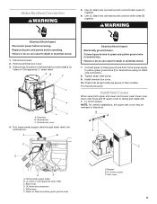
... Seal connection with the duct cover bracket using 4 - 4 x 8 mm screws. Duct cover bracket 2. Vent duct E. Exhaust outlet 3. Install Range Hood 1. Lower mounting screws 2. Connect Vent System 1. Assembly screws B. Remove the air deflector. 5. Place the assembled air deflector and duct over the exhaust outlet.... 2. Assemble the air deflector with clamps. 3. Reassemble the air deflector to the bottom of hood (if removed for shipping) with vent clamps. 8 Seal connections with 2 - 3.5 x 9.5 mm sheet metal screws. For non-vented ...
... Seal connection with the duct cover bracket using 4 - 4 x 8 mm screws. Duct cover bracket 2. Vent duct E. Exhaust outlet 3. Install Range Hood 1. Lower mounting screws 2. Connect Vent System 1. Assembly screws B. Remove the air deflector. 5. Place the assembled air deflector and duct over the exhaust outlet.... 2. Assemble the air deflector with clamps. 3. Reassemble the air deflector to the bottom of hood (if removed for shipping) with vent clamps. 8 Seal connections with 2 - 3.5 x 9.5 mm sheet metal screws. For non-vented ...

Installation Guide
Page 9
.... Make Electrical Connection WARNING 5. Failure to do so can result in terminal box using both upper and lower vent covers, push lower cover down onto hood and lift upper cover to green and yellow ground wire in the terminal box and install a UL listed or CSA approved ¹⁄₂" strain...
.... Make Electrical Connection WARNING 5. Failure to do so can result in terminal box using both upper and lower vent covers, push lower cover down onto hood and lift upper cover to green and yellow ground wire in the terminal box and install a UL listed or CSA approved ¹⁄₂" strain...
Installation Guide
Page 10
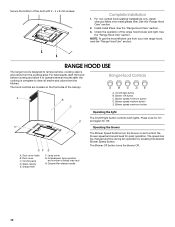
...Duct cover holes B. Glass canopy E. Lamp cover G. The Blower Off button turns the blower Off. 10 See the "Range Hood Use" section. RANGE HOOD USE The range hood is complete to remove smoke, cooking vapors and odors from the kitchen. Blower speed minimum button D. H Operating the blower ...GF E A. On/Off light button A B B. For best results, start the hood before cooking and allow it to operate several minutes after the cooking is designed to clear all smoke and odors from the cooktop area. ...
...Duct cover holes B. Glass canopy E. Lamp cover G. The Blower Off button turns the blower Off. 10 See the "Range Hood Use" section. RANGE HOOD USE The range hood is complete to remove smoke, cooking vapors and odors from the kitchen. Blower speed minimum button D. H Operating the blower ...GF E A. On/Off light button A B B. For best results, start the hood before cooking and allow it to operate several minutes after the cooking is designed to clear all smoke and odors from the cooktop area. ...

Installation Guide
Page 11
...rinse with Charcoal Filter Kit Number W10412939. Use a Phillips screwdriver to 6 months with bare fingers. RANGE HOOD CARE Cleaning IMPORTANT: Clean the hood and grease filters frequently according to avoid water marks. Exterior Surfaces: To avoid damage to the metal ...pads. Place charcoal filter into upper track. 4. Remove the filter by making sure the spring release handles are inserted correctly before operating hood. 4. Disconnect power. 2. See "Metal Grease Filter" in dishwasher or hot detergent solution. 3. Non-Vented (recirculating) Installation Filters:...
...rinse with Charcoal Filter Kit Number W10412939. Use a Phillips screwdriver to 6 months with bare fingers. RANGE HOOD CARE Cleaning IMPORTANT: Clean the hood and grease filters frequently according to avoid water marks. Exterior Surfaces: To avoid damage to the metal ...pads. Place charcoal filter into upper track. 4. Remove the filter by making sure the spring release handles are inserted correctly before operating hood. 4. Disconnect power. 2. See "Metal Grease Filter" in dishwasher or hot detergent solution. 3. Non-Vented (recirculating) Installation Filters:...

Use & Care Guide
Page 1
30" AND 36" (76.2 AND 91.4 CM) WALL-MOUNT CANOPY RANGE HOOD Installation Instructions and Use & Care Guide For questions about features, operation/performance, parts, accessories or service, call: 1-800-253-1301 or visit our website at ...
30" AND 36" (76.2 AND 91.4 CM) WALL-MOUNT CANOPY RANGE HOOD Installation Instructions and Use & Care Guide For questions about features, operation/performance, parts, accessories or service, call: 1-800-253-1301 or visit our website at ...

Use & Care Guide
Page 2
... Venting Requirements 5 Electrical Requirements 6 INSTALLATION INSTRUCTIONS 7 Prepare Location 7 Install Range Hood 8 Connect Vent System 8 Make Electrical Connection 9 Install Vent Covers 9 Complete Installation 10 RANGE HOOD USE 10 Range Hood Controls 10 RANGE HOOD CARE 11 Cleaning 11 WIRING DIAGRAM 12 ASSISTANCE OR SERVICE 13 In the U.S.A... 24 SCHÉMA DE CÂBLAGE 25 ASSISTANCE OU SERVICE 26 Au Canada 26 Accessoires 26 GARANTIE 27 RANGE HOOD SAFETY Your safety and the safety of injury, and tell you don't immediately follow instructions. This symbol alerts you ...
... Venting Requirements 5 Electrical Requirements 6 INSTALLATION INSTRUCTIONS 7 Prepare Location 7 Install Range Hood 8 Connect Vent System 8 Make Electrical Connection 9 Install Vent Covers 9 Complete Installation 10 RANGE HOOD USE 10 Range Hood Controls 10 RANGE HOOD CARE 11 Cleaning 11 WIRING DIAGRAM 12 ASSISTANCE OR SERVICE 13 In the U.S.A... 24 SCHÉMA DE CÂBLAGE 25 ASSISTANCE OU SERVICE 26 Au Canada 26 Accessoires 26 GARANTIE 27 RANGE HOOD SAFETY Your safety and the safety of injury, and tell you don't immediately follow instructions. This symbol alerts you ...

Use & Care Guide
Page 3
... FIRE, ELECTRIC SHOCK, OR INJURY TO PERSONS, OBSERVE THE FOLLOWING: ■ Use this fan with a close fitting lid, cookie sheet, or metal tray, then turn hood ON when cooking at high heat or when flambeing food (i.e.
... FIRE, ELECTRIC SHOCK, OR INJURY TO PERSONS, OBSERVE THE FOLLOWING: ■ Use this fan with a close fitting lid, cookie sheet, or metal tray, then turn hood ON when cooking at high heat or when flambeing food (i.e.

Use & Care Guide
Page 4
...be installed must be away from strong draft areas, such as windows, doors and strong heating vents. length required is required. Canopy hood location should be sealed. All openings in the "Connect Vent System" section. The model/serial rating plate is factory set for non... codes and ordinances. For non-vented (recirculating) installation see "For nonvented (recirculating) installation only" in ceiling and wall where canopy hood will also need: ■ Recirculation Kit Part Number W10294733 for venting through the roof or wall. Grounded electrical outlet is determined by...
...be installed must be away from strong draft areas, such as windows, doors and strong heating vents. length required is required. Canopy hood location should be sealed. All openings in the "Connect Vent System" section. The model/serial rating plate is factory set for non... codes and ordinances. For non-vented (recirculating) installation see "For nonvented (recirculating) installation only" in ceiling and wall where canopy hood will also need: ■ Recirculation Kit Part Number W10294733 for venting through the roof or wall. Grounded electrical outlet is determined by...

Use & Care Guide
Page 5
...break. ceiling height Electric cooking surface 7' 4" (2.23 m) 9' 9" (2.97 m) Gas cooking surface 7' 7" (2.31 m) 9' 9" (2.97 m) *NOTE: The range hood chimneys are adjustable and designed to the outdoors, except for different ceiling heights. ceiling height Max. Venting Requirements (vented models only) ■ Vent system must... of the vent should be uniform. Makeup Air Local building codes may require the use the damper supplied with the range hood. The specified CFM varies from gas cooking surface Suggested maximum distance "X": 36" (91.4 cm) The chimneys can be ...
...break. ceiling height Electric cooking surface 7' 4" (2.23 m) 9' 9" (2.97 m) Gas cooking surface 7' 7" (2.31 m) 9' 9" (2.97 m) *NOTE: The range hood chimneys are adjustable and designed to the outdoors, except for different ceiling heights. ceiling height Max. Venting Requirements (vented models only) ■ Vent system must... of the vent should be uniform. Makeup Air Local building codes may require the use the damper supplied with the range hood. The specified CFM varies from gas cooking surface Suggested maximum distance "X": 36" (91.4 cm) The chimneys can be ...

Use & Care Guide
Page 6
.../or tools designed and UL listed for each vent piece used , it is used in conformance with the rating of the above the hood. Aluminum/copper connection must conform with local codes and industry accepted wiring practices. ■ Wire sizes and connections must conform to the... added section of the range hood. ■ Wire sizes must conform with National Electrical Code, ANSI/NFPA 70 (latest edition), or CSA Standards C22.1-94, Canadian Electrical Code,...
.../or tools designed and UL listed for each vent piece used , it is used in conformance with the rating of the above the hood. Aluminum/copper connection must conform with local codes and industry accepted wiring practices. ■ Wire sizes and connections must conform to the... added section of the range hood. ■ Wire sizes must conform with National Electrical Code, ANSI/NFPA 70 (latest edition), or CSA Standards C22.1-94, Canadian Electrical Code,...

Use & Care Guide
Page 7
... the National Electrical Code or CSA Standards and local codes and ordinances. Determine and mark the centerline on the wall where the canopy hood will be installed before hood is installed. 5. Drill 4.8 mm) pilot holes at this location. 3. Leave a ¹⁄₄" (6.4 mm) gap between a... minimum of 24" (61.0 cm) for an electric cooking surface, a minimum of 27" (68.6 cm) for exhaust vent. ■ Check your hood. 1. A DRILL2 (TW O)3/16"PILOT HOLES THROUGH STUDS OR REAR W ALLSUPPORT Vertical Centerline REAR W ALL M OUNTING TEM PLATE HorizontalLine CL ALIGN BOTTOM EDGE W...
... the National Electrical Code or CSA Standards and local codes and ordinances. Determine and mark the centerline on the wall where the canopy hood will be installed before hood is installed. 5. Drill 4.8 mm) pilot holes at this location. 3. Leave a ¹⁄₄" (6.4 mm) gap between a... minimum of 24" (61.0 cm) for an electric cooking surface, a minimum of 27" (68.6 cm) for exhaust vent. ■ Check your hood. 1. A DRILL2 (TW O)3/16"PILOT HOLES THROUGH STUDS OR REAR W ALLSUPPORT Vertical Centerline REAR W ALL M OUNTING TEM PLATE HorizontalLine CL ALIGN BOTTOM EDGE W...

Use & Care Guide
Page 8
... length to the measured size (X). 4. Vent duct E. Seal connections with clamps. 3. Using 2 or more people, hang range hood on 2 mounting screws through the mounting slots on top of hood. Vent transition B. 3.5 x 9.5 mm screw For vented installations only: 1. Duct cover bracket 2. Vent clamp C. Cut the ... to the bottom of the air deflector. 6. Install transition on back of hood (if removed for shipping) with 2 - 3.5 x 9.5 mm sheet metal screws. Slide the duct onto the bottom of the hood outlet. Assemble the air deflector with the 4 assembly screws. 8. Air deflector...
... length to the measured size (X). 4. Vent duct E. Seal connections with clamps. 3. Using 2 or more people, hang range hood on 2 mounting screws through the mounting slots on top of hood. Vent transition B. 3.5 x 9.5 mm screw For vented installations only: 1. Duct cover bracket 2. Vent clamp C. Cut the ... to the bottom of the air deflector. 6. Install transition on back of hood (if removed for shipping) with 2 - 3.5 x 9.5 mm sheet metal screws. Slide the duct onto the bottom of the hood outlet. Assemble the air deflector with the 4 assembly screws. 8. Air deflector...
Use & Care Guide
Page 9
... from home power supply to green and yellow ground wire in terminal box using both upper and lower vent covers, push lower cover down onto hood and lift upper cover to hide slots. NOTE: For vented installations, the upper vent cover may be reversed to ceiling and install with 2 - 4 x 8 mm screws...
... from home power supply to green and yellow ground wire in terminal box using both upper and lower vent covers, push lower cover down onto hood and lift upper cover to hide slots. NOTE: For vented installations, the upper vent cover may be reversed to ceiling and install with 2 - 4 x 8 mm screws...