
Product Guide
Page 2
... NOT KNOW WHICH TYPE OF LICENSE YOU HAVE ACQUIRED, PLEASE CONSULT THE SALES AND OTHER RELATED LICENSE GRANT OR PURCHASE ORDER DOCUMENTS THAT ACCOMPANIES YOUR SOFTWARE PACKAGING OR THAT YOU HAVE RECEIVED SEPARATELY AS PART OF THE PURCHASE (AS A BOOKLET, A FILE ON THE PRODUCT CD, OR A FILE AVAILABLE ON THE WEB SITE FROM WHICH YOU DOWNLOADED THE SOFTWARE PACKAGE). Siek...
... NOT KNOW WHICH TYPE OF LICENSE YOU HAVE ACQUIRED, PLEASE CONSULT THE SALES AND OTHER RELATED LICENSE GRANT OR PURCHASE ORDER DOCUMENTS THAT ACCOMPANIES YOUR SOFTWARE PACKAGING OR THAT YOU HAVE RECEIVED SEPARATELY AS PART OF THE PURCHASE (AS A BOOKLET, A FILE ON THE PRODUCT CD, OR A FILE AVAILABLE ON THE WEB SITE FROM WHICH YOU DOWNLOADED THE SOFTWARE PACKAGE). Siek...
Product Guide
Page 3
... I-1400...10 Installing the ears on the chassis 10 Cabling the sensor ...12 Powering on the sensor...12 Powering off the sensor ...12 Chapter 4 Attaching cables to the I-1400 Sensor 13 Cabling the Console port...13 Cabling the Auxiliary port ...13 Cabling the Response ports ...14 Cabling the Management port ...14 Cabling the Monitoring ports ...15 Using peer ports ...15 Default Monitoring port speed settings 15 Cable types for routers, switches, hubs, and PCs 16 Using fail-closed dongles ...16 Cabling for in-line mode ...17 Cabling the I-1400 to...
... I-1400...10 Installing the ears on the chassis 10 Cabling the sensor ...12 Powering on the sensor...12 Powering off the sensor ...12 Chapter 4 Attaching cables to the I-1400 Sensor 13 Cabling the Console port...13 Cabling the Auxiliary port ...13 Cabling the Response ports ...14 Cabling the Management port ...14 Cabling the Monitoring ports ...15 Using peer ports ...15 Default Monitoring port speed settings 15 Cable types for routers, switches, hubs, and PCs 16 Using fail-closed dongles ...16 Cabling for in-line mode ...17 Cabling the I-1400 to...

Product Guide
Page 4
... panel LEDs. • Chapter 2: Before You Install (on page 5) contains system specifications, and the safety and usage requirements for the sensors. • Chapter 3: Setting up an I-1400 Sensor (on page 10) describes the preliminary steps you want to do you must follow prior to configuring the sensor. • Chapter 4: Attaching Cables to the I -1400 sensor. Preface This preface provides a brief introduction to McAfee IntruShield, discusses...
... panel LEDs. • Chapter 2: Before You Install (on page 5) contains system specifications, and the safety and usage requirements for the sensors. • Chapter 3: Setting up an I-1400 Sensor (on page 10) describes the preliminary steps you want to do you must follow prior to configuring the sensor. • Chapter 4: Attaching Cables to the I -1400 sensor. Preface This preface provides a brief introduction to McAfee IntruShield, discusses...

Product Guide
Page 5
..., and commands on the Properties tab specifies the name of numbered steps. 1. Conventions used by network technicians and maintenance personnel who are responsible for installing, configuring, and maintaining this notation. using a right angle bracket. Note: v on the keyboard are indicated Select My Company > Admin Domain > View Details. set sensor ip Information that you must type exactly are presented as a series of the requested service. using UPPER...
..., and commands on the Properties tab specifies the name of numbered steps. 1. Conventions used by network technicians and maintenance personnel who are responsible for installing, configuring, and maintaining this notation. using a right angle bracket. Note: v on the keyboard are indicated Select My Company > Admin Domain > View Details. set sensor ip Information that you must type exactly are presented as a series of the requested service. using UPPER...

Product Guide
Page 10
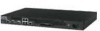
... your network (For example, via a switch or router). 7 Power supply. that is used to monitor four SPAN ports, two fullduplex tapped segment, or two segment in-line. Ports on the I-1400 The I -1400 sensor. these channels provide link privacy using encryption and mutual authentication between the sensor and the ISM server uses secure channels; International customers must procure a country-appropriate power cable. 2 This sensor can monitor up and configure the sensor. 3 One 10/100 Management port, which enable you to IPS...
... your network (For example, via a switch or router). 7 Power supply. that is used to monitor four SPAN ports, two fullduplex tapped segment, or two segment in-line. Ports on the I-1400 The I -1400 sensor. these channels provide link privacy using encryption and mutual authentication between the sensor and the ISM server uses secure channels; International customers must procure a country-appropriate power cable. 2 This sensor can monitor up and configure the sensor. 3 One 10/100 Management port, which enable you to IPS...
Product Guide
Page 11
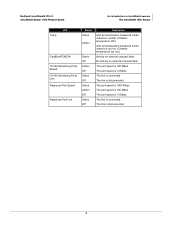
McAfee® IntruShield® IPS 4.1 IntruShield Sensor 1400 Product Guide An introduction to IntruShield sensors The IntruShield 1400 Sensor 8 Built-in -line mode. The internal tap (used with the 10/100 ports) provide stealth mode monitoring functionality and forgo the need of the sensor and the activity on its ports. You can accomplish this via cabling. The sensor is powered off or is rebooting. The port speed is 100 Mbps The port speed is 10 Mbps The link is working fine after...
McAfee® IntruShield® IPS 4.1 IntruShield Sensor 1400 Product Guide An introduction to IntruShield sensors The IntruShield 1400 Sensor 8 Built-in -line mode. The internal tap (used with the 10/100 ports) provide stealth mode monitoring functionality and forgo the need of the sensor and the activity on its ports. You can accomplish this via cabling. The sensor is powered off or is rebooting. The port speed is 100 Mbps The port speed is 10 Mbps The link is working fine after...
Product Guide
Page 12
The link is disconnected. 4 The link is disconnected. The port speed is 1000 Mbps The port speed is 100 Mbps The port speed is 10 Mbps The link is connected. The port speed is 100 Mbps The port speed is 10 Mbps The link is connected. McAfee® IntruShield® IPS 4.1 IntruShield Sensor 1400 Product Guide An introduction to IntruShield sensors The IntruShield 1400 Sensor LED Temp CardBus/PCMCIA 10/100 Monitoring Ports Speed 10/100 Monitoring Ports Link Response Port Speed Response Port Link Status Green Amber Green Off...
The link is disconnected. 4 The link is disconnected. The port speed is 1000 Mbps The port speed is 100 Mbps The port speed is 10 Mbps The link is connected. The port speed is 100 Mbps The port speed is 10 Mbps The link is connected. McAfee® IntruShield® IPS 4.1 IntruShield Sensor 1400 Product Guide An introduction to IntruShield sensors The IntruShield 1400 Sensor LED Temp CardBus/PCMCIA 10/100 Monitoring Ports Speed 10/100 Monitoring Ports Link Response Port Speed Response Port Link Status Green Amber Green Off...

Product Guide
Page 14
Sensor capacity for I-1400 sensor The following cabling specifications for the sensor: • Category 5 Enhanced (Cat 5e) cable is required for I -1400 Concurrent connections Connections established per sec. Concurrent SSL Flows (2.1.x and later) Number of SSL keys that can be stored on the sensor 80,000 2,000 NA NA Virtual Interfaces (VIDS) 32 VLANS / CIDR Blocks 64 VLANS / CIDR Blocks per Physical Port Customized attacks Alert filters Default number of supported UDP Flows Supported UDP Flows 64...
Sensor capacity for I-1400 sensor The following cabling specifications for the sensor: • Category 5 Enhanced (Cat 5e) cable is required for I -1400 Concurrent connections Connections established per sec. Concurrent SSL Flows (2.1.x and later) Number of SSL keys that can be stored on the sensor 80,000 2,000 NA NA Virtual Interfaces (VIDS) 32 VLANS / CIDR Blocks 64 VLANS / CIDR Blocks per Physical Port Customized attacks Alert filters Default number of supported UDP Flows Supported UDP Flows 64...
Product Guide
Page 16
... of the FCC Rules. McAfee® IntruShield® IPS 4.1 IntruShield Sensor 1400 Product Guide Before you install Safety measures Safety measures The safety measures given below apply to power lines, remove jewelry (including rings, necklaces, and watches). Failure to hazardous voltages and currents inside the chassis, contain electromagnetic interference (EMI) that might be allowed to comply with the limits for example, FDDI, OC-3, OC-12...
... of the FCC Rules. McAfee® IntruShield® IPS 4.1 IntruShield Sensor 1400 Product Guide Before you install Safety measures Safety measures The safety measures given below apply to power lines, remove jewelry (including rings, necklaces, and watches). Failure to hazardous voltages and currents inside the chassis, contain electromagnetic interference (EMI) that might be allowed to comply with the limits for example, FDDI, OC-3, OC-12...

Product Guide
Page 17
McAfee® IntruShield® IPS 4.1 IntruShield Sensor 1400 Product Guide Before you install Usage restrictions Usage restrictions The following accessories are listed on -line documentation. • One power cord. These parts are shipped in the sensor box: • One sensor • One CD-ROM containing the sensor software and on the packing list and in Contents of the sensor. International customers must procure a country-appropriate power cable with the text upright. 3 Open the top...
McAfee® IntruShield® IPS 4.1 IntruShield Sensor 1400 Product Guide Before you install Usage restrictions Usage restrictions The following accessories are listed on -line documentation. • One power cord. These parts are shipped in the sensor box: • One sensor • One CD-ROM containing the sensor software and on the packing list and in Contents of the sensor. International customers must procure a country-appropriate power cable with the text upright. 3 Open the top...
Product Guide
Page 18
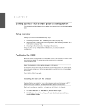
... secure location, close to the switches or routers it via the ISM. Note: The illustrations in a rack, you have all network interface cables from the sensor. The I-1400 is OFF. To mount the sensor in this section show an I-1200 sensor. Setup overview Setting up a sensor involves the following steps: 1 Positioning the sensor. (See Positioning the I-1400 (on page 10)) 2 Attaching power, network, and monitoring cables. (See Attaching Cables to the I- 1400 Sensor...
... secure location, close to the switches or routers it via the ISM. Note: The illustrations in a rack, you have all network interface cables from the sensor. The I-1400 is OFF. To mount the sensor in this section show an I-1200 sensor. Setup overview Setting up a sensor involves the following steps: 1 Positioning the sensor. (See Positioning the I-1400 (on page 10)) 2 Attaching power, network, and monitoring cables. (See Attaching Cables to the I- 1400 Sensor...

Product Guide
Page 20
... IPS 4.1 IntruShield Sensor 1400 Product Guide Setting up the I-1400 sensor prior to configuration Cabling the sensor Figure 2: Mounting the I -1400 Sensor (on page 13) to connect cables to the monitoring, response, console, and management ports on the sensor until you use the shutdown CLI command to a power source. Powering off the sensor McAfee recommends that you have installed the sensor in Attaching Cables to the I -1400 sensor in a rack Cabling the sensor Follow the steps outlined in a rack, made all necessary network connections, and connected the power cable to the power supply...
... IPS 4.1 IntruShield Sensor 1400 Product Guide Setting up the I-1400 sensor prior to configuration Cabling the sensor Figure 2: Mounting the I -1400 Sensor (on page 13) to connect cables to the monitoring, response, console, and management ports on the sensor until you use the shutdown CLI command to a power source. Powering off the sensor McAfee recommends that you have installed the sensor in Attaching Cables to the I -1400 sensor in a rack Cabling the sensor Follow the steps outlined in a rack, made all necessary network connections, and connected the power cable to the power supply...

Product Guide
Page 21
... Stop bits Flow Control 9600 8 None 1 None 3 Power on your sensor. Required settings for example, a PC running correctly configured Windows HyperTerminal software). Required settings for setup and configuration. Cabling the Console port The Console port is used for initial configuration. CHAPTER 4 Attaching cables to the I-1400 Sensor Follow the steps outlined in this chapter to connect cables to the various ports on the sensor. Cabling the Auxiliary port The Auxiliary (Aux) port is used for modem access to the sensor for HyperTerminal are...
... Stop bits Flow Control 9600 8 None 1 None 3 Power on your sensor. Required settings for example, a PC running correctly configured Windows HyperTerminal software). Required settings for setup and configuration. Cabling the Console port The Console port is used for initial configuration. CHAPTER 4 Attaching cables to the I-1400 Sensor Follow the steps outlined in this chapter to connect cables to the various ports on the sensor. Cabling the Auxiliary port The Auxiliary (Aux) port is used for modem access to the sensor for HyperTerminal are...

Product Guide
Page 22
... ISM. 14 McAfee® IntruShield® IPS 4.1 IntruShield Sensor 1400 Product Guide Attaching cables to the I-1400 Sensor Cabling the Response ports Name Baud rate Number of the cable to the network device (for example, hub, switch, router) through which you want to respond to attacks. Cabling the Response ports The sensor's Response ports are : • 9600 bps port speed • Answer after 1 ring • Save the configuration to NVRAM. Cabling the Management port The Management (Mgmt) port is used to send responses...
... ISM. 14 McAfee® IntruShield® IPS 4.1 IntruShield Sensor 1400 Product Guide Attaching cables to the I-1400 Sensor Cabling the Response ports Name Baud rate Number of the cable to the network device (for example, hub, switch, router) through which you want to respond to attacks. Cabling the Response ports The sensor's Response ports are : • 9600 bps port speed • Answer after 1 ring • Save the configuration to NVRAM. Cabling the Management port The Management (Mgmt) port is used to send responses...

Product Guide
Page 23
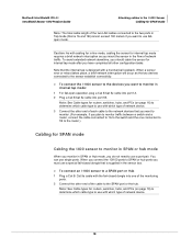
... ports) Default monitoring port speed settings Make sure that the switch/router ports connected to the sensor monitoring ports match the sensor configuration. 15 Cabling instructions for each monitoring mode: To cable the I -1400 Note: You cannot configure, for the sensor Monitoring ports are shown on the sensor. The following table. You can deploy sensors in the operating modes shown in the following ports are wired in pairs to accommodate the traffic. See... On the sensors, the numbered ports are...
... ports) Default monitoring port speed settings Make sure that the switch/router ports connected to the sensor monitoring ports match the sensor configuration. 15 Cabling instructions for each monitoring mode: To cable the I -1400 Note: You cannot configure, for the sensor Monitoring ports are shown on the sensor. The following table. You can deploy sensors in the operating modes shown in the following ports are wired in pairs to accommodate the traffic. See... On the sensors, the numbered ports are...

Product Guide
Page 24
... ports Default monitoring port speed settings: Monitoring Ports Operating Mode Speed/Duplex Setting SPAN Tap 10/100 ports In-line Auto-negotiation is ON; You plug the dongle into a sensor 10/100 monitoring port, and then connect a Cat 5/Cat 5e cable to the sensor monitoring port. McAfee® IntruShield® IPS 4.1 IntruShield Sensor 1400 Product Guide Attaching cables to the I -1400 sensor. Speed and Duplex are configurable Auto-negotiation is OFF; The following table lists the operating modes where dongles should also use...
... ports Default monitoring port speed settings: Monitoring Ports Operating Mode Speed/Duplex Setting SPAN Tap 10/100 ports In-line Auto-negotiation is ON; You plug the dongle into a sensor 10/100 monitoring port, and then connect a Cat 5/Cat 5e cable to the sensor monitoring port. McAfee® IntruShield® IPS 4.1 IntruShield Sensor 1400 Product Guide Attaching cables to the I -1400 sensor. Speed and Duplex are configurable Auto-negotiation is OFF; The following table lists the operating modes where dongles should also use...

Product Guide
Page 25
...). McAfee® IntruShield® IPS 4.1 IntruShield Sensor 1400 Product Guide Cabling for in-line mode Attaching cables to the I-1400 Sensor Cabling for in-line mode Cabling the I-1400 to monitor in in-line mode In-line mode requires that you use a pair of the following: For fail-closed operation, plug a Cat 5/Cat 5e cable with which cable type to use with a fail-closed dongle will interrupt traffic if the sensor fails. Caution: Cabling sensors for in-line mode requires a brief network interruption as you insert it allows traffic to...
...). McAfee® IntruShield® IPS 4.1 IntruShield Sensor 1400 Product Guide Cabling for in-line mode Attaching cables to the I-1400 Sensor Cabling for in-line mode Cabling the I-1400 to monitor in in-line mode In-line mode requires that you use a pair of the following: For fail-closed operation, plug a Cat 5/Cat 5e cable with which cable type to use with a fail-closed dongle will interrupt traffic if the sensor fails. Caution: Cabling sensors for in-line mode requires a brief network interruption as you insert it allows traffic to...
Product Guide
Page 26
...; IPS 4.1 IntruShield Sensor 1400 Product Guide Attaching cables to the I -1400 sensor to the devices you want to monitor in internal tap mode: 1 For fail-open operation, plug a Cat 5/Cat 5e cable into port 1A. 2 Plug a Cat 5/Cat 5e cable into one connected to 1B to the router.) Cabling for routers, switches, hubs, and PCs (on page 16) to determine which type of network device. 3 Connect the other end of network traffic. Caution: As with cabling for in-line mode, cabling...
...; IPS 4.1 IntruShield Sensor 1400 Product Guide Attaching cables to the I -1400 sensor to the devices you want to monitor in internal tap mode: 1 For fail-open operation, plug a Cat 5/Cat 5e cable into port 1A. 2 Plug a Cat 5/Cat 5e cable into one connected to 1B to the router.) Cabling for routers, switches, hubs, and PCs (on page 16) to determine which type of network device. 3 Connect the other end of network traffic. Caution: As with cabling for in-line mode, cabling...
Product Guide
Page 27
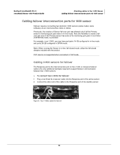
...The Response port is the only additional hardware required to support failover communication between two I-1400 sensors. ► To connect two I -1400. McAfee® IntruShield® IPS 4.1 IntruShield Sensor 1400 Product Guide Attaching cables to the I-1400 Sensor Cabling failover interconnection ports for 1400 sensor Cabling failover interconnection ports for 1400 sensor Failover requires connecting two identical I -1400, you may have port pairs 1A-1B configured in in-line mode and ports 2A-2B configured in SPAN mode. For example, in an I -1400 sensors (same model, same software) via an...
...The Response port is the only additional hardware required to support failover communication between two I-1400 sensors. ► To connect two I -1400. McAfee® IntruShield® IPS 4.1 IntruShield Sensor 1400 Product Guide Attaching cables to the I-1400 Sensor Cabling failover interconnection ports for 1400 sensor Cabling failover interconnection ports for 1400 sensor Failover requires connecting two identical I -1400, you may have port pairs 1A-1B configured in in-line mode and ports 2A-2B configured in SPAN mode. For example, in an I -1400 sensors (same model, same software) via an...
Product Guide
Page 28
... 2 B boot LED 3 C cabling 13, 14, 15, 16, 18, 19 cabling for internal tap mode 19 cabling instructions 13 cabling the auxiliary port 14 cabling the console port 14 CardBus/PCMCIA port 2 CardBus/PCMCIA LED 3 configuration overview 11 connecting to sensor 15 D default speed settings 17 describing an IntruShield sensor 1 dongles 20 F fail-closed dongle 2 fan LED 3 front panel LEDs 3 G GBIC Monitoring ports speed settings 17 H heat requirements 5 I in-line mode 18 deployment 18 internal tap mode 19 L LED description 3 link LED 3 M management port 2 management port link...
... 2 B boot LED 3 C cabling 13, 14, 15, 16, 18, 19 cabling for internal tap mode 19 cabling instructions 13 cabling the auxiliary port 14 cabling the console port 14 CardBus/PCMCIA port 2 CardBus/PCMCIA LED 3 configuration overview 11 connecting to sensor 15 D default speed settings 17 describing an IntruShield sensor 1 dongles 20 F fail-closed dongle 2 fan LED 3 front panel LEDs 3 G GBIC Monitoring ports speed settings 17 H heat requirements 5 I in-line mode 18 deployment 18 internal tap mode 19 L LED description 3 link LED 3 M management port 2 management port link...


