User Guide
Page 1
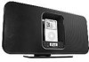
Mi1006 User's Guide iListen with AM/FM Radio Before operating this product, please read these instructions completely.
Mi1006 User's Guide iListen with AM/FM Radio Before operating this product, please read these instructions completely.
User Guide
Page 2
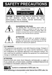
NO USERSERVICEABLE PARTS INSIDE. REFER SERVICING TO QUALIFIED SERVICE PERSONNEL. DANGEROUS VOLTAGE: The lightning flash with arrowhead symbol within an equilateral triangle is intended to alert the user to the presence of important operating and maintenance (servicing) instructions in the instruction manual. ATTENTION: The ...FOND. 1 SAFETY PRECAUTIONS CAUTION RISK OF ELECTRIC SHOCK DO NOT OPEN CAUTION: TO REDUCE THE RISK OF ELECTRIC SHOCK, DO NOT REMOVE COVER (OR BACK). Changes or modifications to operate this equipment may generate or use radio frequency energy.
NO USERSERVICEABLE PARTS INSIDE. REFER SERVICING TO QUALIFIED SERVICE PERSONNEL. DANGEROUS VOLTAGE: The lightning flash with arrowhead symbol within an equilateral triangle is intended to alert the user to the presence of important operating and maintenance (servicing) instructions in the instruction manual. ATTENTION: The ...FOND. 1 SAFETY PRECAUTIONS CAUTION RISK OF ELECTRIC SHOCK DO NOT OPEN CAUTION: TO REDUCE THE RISK OF ELECTRIC SHOCK, DO NOT REMOVE COVER (OR BACK). Changes or modifications to operate this equipment may generate or use radio frequency energy.
User Guide
Page 3
... the instructions, may cause harmful interference to radio communications. However, there is connected. • Consult the dealer or an experienced radio/TV technician for help. WARNING: TO PREVENT FIRE OR SHOCK HAZARD, DO NOT EXPOSE THIS UNIT TO RAIN OR MOISTURE. Lightning and power surges ARE NOT covered under warranty for AC connection. This Class B digital apparatus...
... the instructions, may cause harmful interference to radio communications. However, there is connected. • Consult the dealer or an experienced radio/TV technician for help. WARNING: TO PREVENT FIRE OR SHOCK HAZARD, DO NOT EXPOSE THIS UNIT TO RAIN OR MOISTURE. Lightning and power surges ARE NOT covered under warranty for AC connection. This Class B digital apparatus...
User Guide
Page 4
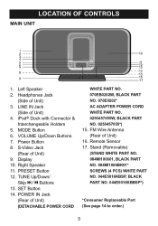
... CONTROLS MAIN UNIT 1. Headphones Jack (Side of Unit) 9. Right Speaker 11. Remote Sensor 17. Stand (Removable) (STAND WHITE PART NO. 084MI100601, BLACK PART NO. 084MI1006BK01* SCREWS (4 PCS) WHITE PART NO. 044E5016KBSP, BLACK PART NO. 044E5016KBBSP*) *Consumer Replaceable Part (See page 14 to order.) 3 VOLUME Up/Down Buttons 7. SET Button 14. Power Button 8. S-Video Jack (Rear of Unit) 3. FM Wire Antenna (Rear of Unit) 4. iPod® Dock with Connector & Interchangeable Holders 5. MODE Button 6. Left Speaker 2. LINE IN Jack...
... CONTROLS MAIN UNIT 1. Headphones Jack (Side of Unit) 9. Right Speaker 11. Remote Sensor 17. Stand (Removable) (STAND WHITE PART NO. 084MI100601, BLACK PART NO. 084MI1006BK01* SCREWS (4 PCS) WHITE PART NO. 044E5016KBSP, BLACK PART NO. 044E5016KBBSP*) *Consumer Replaceable Part (See page 14 to order.) 3 VOLUME Up/Down Buttons 7. SET Button 14. Power Button 8. S-Video Jack (Rear of Unit) 3. FM Wire Antenna (Rear of Unit) 4. iPod® Dock with Connector & Interchangeable Holders 5. MODE Button 6. Left Speaker 2. LINE IN Jack...
User Guide
Page 5
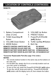
... REMOTE CONTROL WHITE PART NO. RC-MI3005* REMOTE CONTROL BLACK PART NO. To turn on the unit, press the Power/PLAY/PAUSE (®p) button. TUNE Down/Skip o 7. TUNE Up/Skip n Button 4. PRESET Button 2. VOLUME Down Button 8. RC-MI3005RBLK* REMOTE BATTERY DOOR WHITE PART NO. 037MI4004081AA* REMOTE BATTERY DOOR BLACK PART NO. 0374004BK081AA* *Consumer Replaceable Part (See page 14 to order.) NOTES: • The remote buttons function in the same way...
... REMOTE CONTROL WHITE PART NO. RC-MI3005* REMOTE CONTROL BLACK PART NO. To turn on the unit, press the Power/PLAY/PAUSE (®p) button. TUNE Down/Skip o 7. TUNE Up/Skip n Button 4. PRESET Button 2. VOLUME Down Button 8. RC-MI3005RBLK* REMOTE BATTERY DOOR WHITE PART NO. 037MI4004081AA* REMOTE BATTERY DOOR BLACK PART NO. 0374004BK081AA* *Consumer Replaceable Part (See page 14 to order.) NOTES: • The remote buttons function in the same way...
User Guide
Page 6
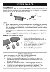
... the AC plug does not fit into the POWER IN jack (located on the tab and then sliding the compartment out. Install a CR2025 battery, paying attention to disconnect the AC adapter when not in on the rear of the unit). Remove the Battery Compartment by pressing in use. • Only use the supplied AC Adapter which has the following specs: DC 12V Z REMOTE BATTERY INSTALLATION 1. 2. 3. BATTERY PRECAUTIONS Follow...
... the AC plug does not fit into the POWER IN jack (located on the tab and then sliding the compartment out. Install a CR2025 battery, paying attention to disconnect the AC adapter when not in on the rear of the unit). Remove the Battery Compartment by pressing in use. • Only use the supplied AC Adapter which has the following specs: DC 12V Z REMOTE BATTERY INSTALLATION 1. 2. 3. BATTERY PRECAUTIONS Follow...
User Guide
Page 7
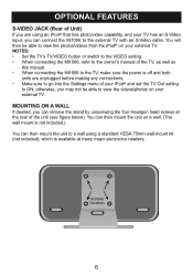
... this manual. • When connecting the Mi1006 to the TV, make sure the power is off and both units are unplugged before making any connections. • Make sure to view the photos/videos from the iPod® on your external TV. otherwise, you may not be able to go into the Settings menu of Unit) If you are using a standard VESA 75mm wall-mount...
... this manual. • When connecting the Mi1006 to the TV, make sure the power is off and both units are unplugged before making any connections. • Make sure to view the photos/videos from the iPod® on your external TV. otherwise, you may not be able to go into the Settings menu of Unit) If you are using a standard VESA 75mm wall-mount...
User Guide
Page 8
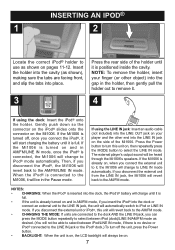
... external player's output sound will always be able to select between iPod (dock)/LINE IN/AM/FM mode as shown on . 7 If the Mi1006 is turned on , when you can press the MODE button repeatedly to select between iPod/LINE IN mode, if there is connected, the Mi1006 will revert back to remove it is inserted into place. 3 Press the rear side of the Mi1006. If the Mi1006 is...
... external player's output sound will always be able to select between iPod (dock)/LINE IN/AM/FM mode as shown on . 7 If the Mi1006 is turned on , when you can press the MODE button repeatedly to select between iPod/LINE IN mode, if there is connected, the Mi1006 will revert back to remove it is inserted into place. 3 Press the rear side of the Mi1006. If the Mi1006 is...
User Guide
Page 9
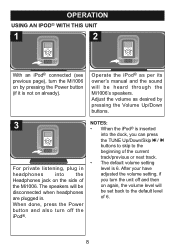
... turn the unit off the iPod®. After your have adjusted the volume setting, if you can press the TUNE Up/Down/Skip n / o buttons to skip to the default level of the current track/previous or next track. • The default volume setting level is inserted into the Headphones jack on already). 11 Operate the iPod® as per its owner's manual and the sound...
... turn the unit off the iPod®. After your have adjusted the volume setting, if you can press the TUNE Up/Down/Skip n / o buttons to skip to the default level of the current track/previous or next track. • The default volume setting level is inserted into the Headphones jack on already). 11 Operate the iPod® as per its owner's manual and the sound...

User Guide
Page 10
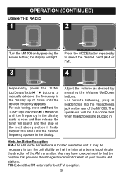
... tabs into the jack, as shown below, before listening to the AM radio for better reception. 1 2 Extend the AM Loop Antenna wire (length is approx. 3 ft). 3 Connect the AM Loop Antenna adapter to fully extend the AM Loop Antenna wire and locate it approx. 3 ft. connect the AM Loop ...best FM reception. Make sure the adapter is an AM Loop Antenna included; Remember to the AM Loop Antenna jack at the rear of the AM Loop Antenna, rotate the stand to the rear and then push the stand to the front. OPERATION (CONTINUED) USING THE RADIO For FM reception, fully extend the FM Wire...
... tabs into the jack, as shown below, before listening to the AM radio for better reception. 1 2 Extend the AM Loop Antenna wire (length is approx. 3 ft). 3 Connect the AM Loop Antenna adapter to fully extend the AM Loop Antenna wire and locate it approx. 3 ft. connect the AM Loop ...best FM reception. Make sure the adapter is an AM Loop Antenna included; Remember to the AM Loop Antenna jack at the rear of the AM Loop Antenna, rotate the stand to the rear and then push the stand to the front. OPERATION (CONTINUED) USING THE RADIO For FM reception, fully extend the FM Wire...
User Guide
Page 11
... strong station it finds. The speakers will be necessary to scan and then release; You may be disconnected when headphones are plugged in the display starts to turn the unit slightly so that provides the strongest reception for best FM reception. 9 the tuner will light. OPERATION (CONTINUED) USING THE RADIO 1 2 Turn the Mi1006 on by pressing the Volume Up/Down buttons.
... strong station it finds. The speakers will be necessary to scan and then release; You may be disconnected when headphones are plugged in the display starts to turn the unit slightly so that provides the strongest reception for best FM reception. 9 the tuner will light. OPERATION (CONTINUED) USING THE RADIO 1 2 Turn the Mi1006 on by pressing the Volume Up/Down buttons.
User Guide
Page 12
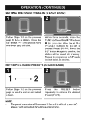
...turn the unit on the previous page to tune a station. Press the SET button "P1" (if no presets have ever been set), will blink. 11 Within three seconds, press the TUNE Up/Down/Skip n / o buttons 1 (or you can also press the PRESET button) to 5 Presets in each band, as desired. Repeat to program... is without power (AC adapter isn't connected) for a long period of time. 10 Press the PRESET button repeatedly to confirm, the station will be saved into memory. Press the SET button 2 again to retrieve the desired Preset (P1-P5). OPERATION (CONTINUED) SETTING THE RADIO PRESETS (5 ...
...turn the unit on the previous page to tune a station. Press the SET button "P1" (if no presets have ever been set), will blink. 11 Within three seconds, press the TUNE Up/Down/Skip n / o buttons 1 (or you can also press the PRESET button) to 5 Presets in each band, as desired. Repeat to program... is without power (AC adapter isn't connected) for a long period of time. 10 Press the PRESET button repeatedly to confirm, the station will be saved into memory. Press the SET button 2 again to retrieve the desired Preset (P1-P5). OPERATION (CONTINUED) SETTING THE RADIO PRESETS (5 ...
User Guide
Page 13
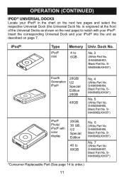
... Universal Dock (the Universal Dock No. S-MI4004IH03, Black Part No. SMI4004BLKIH04*) No. 5 (White Part No. iPod® Type iPod® mini Memory 4 to order.) 11 No. 3 (White Part No. SMI4004BLKIH05*) iPod® Photo/ iPod® with your iPod®. SMI4004BLKIH03*) Fourth Generation iPod® 20GB/ U2 Special Edition 20GB 40GB No. 4 (White Part No. S-MI4004IH06, Black Part No. S-MI4004IH07, Black Part No. SMI4004BLKIH07*) *Consumer Replaceable Part (See...
... Universal Dock (the Universal Dock No. S-MI4004IH03, Black Part No. SMI4004BLKIH04*) No. 5 (White Part No. iPod® Type iPod® mini Memory 4 to order.) 11 No. 3 (White Part No. SMI4004BLKIH05*) iPod® Photo/ iPod® with your iPod®. SMI4004BLKIH03*) Fourth Generation iPod® 20GB/ U2 Special Edition 20GB 40GB No. 4 (White Part No. S-MI4004IH06, Black Part No. S-MI4004IH07, Black Part No. SMI4004BLKIH07*) *Consumer Replaceable Part (See...
User Guide
Page 14
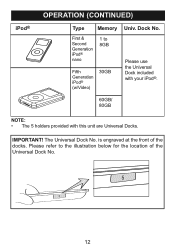
First & Second Generation iPod® nano 1 to the illustration below for the location of the docks. Please refer to 8GB Fifth Generation iPod® (w/Video) 30GB Please use the Universal Dock included with your iPod®. 60GB/ 80GB NOTE: • The 5 holders provided with this unit are Universal Docks. IMPORTANT! The Universal Dock No. Dock No. iPod® OPERATION (CONTINUED) Type Memory Univ. is engraved at the front of the Universal Dock No. 12
First & Second Generation iPod® nano 1 to the illustration below for the location of the docks. Please refer to 8GB Fifth Generation iPod® (w/Video) 30GB Please use the Universal Dock included with your iPod®. 60GB/ 80GB NOTE: • The 5 holders provided with this unit are Universal Docks. IMPORTANT! The Universal Dock No. Dock No. iPod® OPERATION (CONTINUED) Type Memory Univ. is engraved at the front of the Universal Dock No. 12
User Guide
Page 15
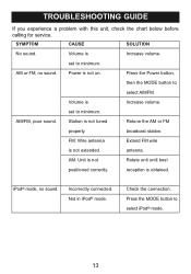
.... iPod® mode, no sound. antenna. reception is not Rotate unit until best positioned correctly. broadcast station. Station is not on. Check the connection. set to select iPod® mode. 13 Power is not tuned Retune the AM or FM properly. set to select AM/FM. AM/FM, poor sound. Not in iPod® mode. Press the MODE button to minimum. Incorrectly connected. Volume is Increase volume. TROUBLESHOOTING GUIDE...
.... iPod® mode, no sound. antenna. reception is not Rotate unit until best positioned correctly. broadcast station. Station is not on. Check the connection. set to select iPod® mode. 13 Power is not tuned Retune the AM or FM properly. set to select AM/FM. AM/FM, poor sound. Not in iPod® mode. Press the MODE button to minimum. Incorrectly connected. Volume is Increase volume. TROUBLESHOOTING GUIDE...
User Guide
Page 16
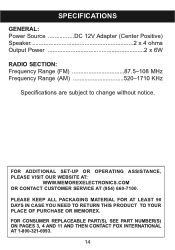
... OF PURCHASE OR MEMOREX. SPECIFICATIONS GENERAL: Power Source DC 12V Adapter (Center Positive) Speaker 2 x 4 ohms Output Power 2 x 6W RADIO SECTION: Frequency Range (FM 87.5-108 MHz Frequency Range (AM 520-1710 KHz Specifications are subject to change without notice. FOR ADDITIONAL SET-UP OR OPERATING ASSISTANCE, PLEASE VISIT OUR WEBSITE AT: WWW.MEMOREXELECTRONICS.COM OR CONTACT CUSTOMER SERVICE AT (954) 660-7100. FOR CONSUMER REPLACEABLE PART(S), SEE PART NUMBER(S) ON PAGES...
... OF PURCHASE OR MEMOREX. SPECIFICATIONS GENERAL: Power Source DC 12V Adapter (Center Positive) Speaker 2 x 4 ohms Output Power 2 x 6W RADIO SECTION: Frequency Range (FM 87.5-108 MHz Frequency Range (AM 520-1710 KHz Specifications are subject to change without notice. FOR ADDITIONAL SET-UP OR OPERATING ASSISTANCE, PLEASE VISIT OUR WEBSITE AT: WWW.MEMOREXELECTRONICS.COM OR CONTACT CUSTOMER SERVICE AT (954) 660-7100. FOR CONSUMER REPLACEABLE PART(S), SEE PART NUMBER(S) ON PAGES...


