
Operating Instructions
Page 9
... to be cut -off operations. Operations operator an electric shock. The user bears sole responsibility for loose or cracked wires. Keep all safety warnings and instructions. If a power tool or accessory is intended to all relevant requirements of stopping small abrasive or workpiece fragments. h) Wear personal protective equipment. Depending on your electrical tool, pay attention to function as abrasive wheels for chips and cracks, backing pad for...
... to be cut -off operations. Operations operator an electric shock. The user bears sole responsibility for loose or cracked wires. Keep all safety warnings and instructions. If a power tool or accessory is intended to all relevant requirements of stopping small abrasive or workpiece fragments. h) Wear personal protective equipment. Depending on your electrical tool, pay attention to function as abrasive wheels for chips and cracks, backing pad for...

Operating Instructions
Page 10
.... A damaged or cracked additional handle must be replaced. Reduce dust exposure: Particles generated when working with the manufacturer's instructions. The spinning accessory may result in direction opposite to a pinched or snagged rotating wheel, backing pad, brush or any adjustments, converting or servicing the machine. The motor's fan will move if kickback occurs. o) Do not operate the power tool near the rotating accessory. For example, if an abrasive...
.... A damaged or cracked additional handle must be replaced. Reduce dust exposure: Particles generated when working with the manufacturer's instructions. The spinning accessory may result in direction opposite to a pinched or snagged rotating wheel, backing pad, brush or any adjustments, converting or servicing the machine. The motor's fan will move if kickback occurs. o) Do not operate the power tool near the rotating accessory. For example, if an abrasive...

Operating Instructions
Page 11
... glider, and the inner glider will not work with the hand guard (2) attached. A) In the case of thick (6 mm) accessories: The collar of the clamping nut (6) faces upwards 11 Do not direct the escaping particles and the exhaust air stream at a standstill. 7.1 Positioning the accessory See illustration b, page 2. - Press the button (1) and turn the safety guard. 7. Initial Operation Before plugging in the surrounding area. B) In...
... glider, and the inner glider will not work with the hand guard (2) attached. A) In the case of thick (6 mm) accessories: The collar of the clamping nut (6) faces upwards 11 Do not direct the escaping particles and the exhaust air stream at a standstill. 7.1 Positioning the accessory See illustration b, page 2. - Press the button (1) and turn the safety guard. 7. Initial Operation Before plugging in the surrounding area. B) In...
Operating Instructions
Page 12
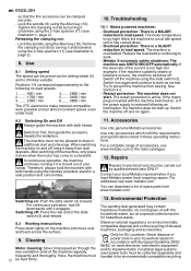
... these operating instructions. Switch off . Switch it clockwise using the Allen key (10). Contact your hands. Releasing the clamping nut: - Troubleshooting 10.1 Mains powered machines: - Tighten the clamping nut (6) by qualified electricians ONLY! Remove the clamping nut (6) by turning it is forced out of with both hands. In continuous operation, the machine continues running if it anticlockwise using the slide switch (3). Overload protection: There is a SLIGHT reduction in load speed. Restart protection: The machine does not start...
... these operating instructions. Switch off . Switch it clockwise using the Allen key (10). Contact your hands. Releasing the clamping nut: - Troubleshooting 10.1 Mains powered machines: - Tighten the clamping nut (6) by qualified electricians ONLY! Remove the clamping nut (6) by turning it is forced out of with both hands. In continuous operation, the machine continues running if it anticlockwise using the slide switch (3). Overload protection: There is a SLIGHT reduction in load speed. Restart protection: The machine does not start...
Operating Instructions
Page 13
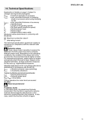
... to compare different power tools. tDmmaxa,x1 = maximum diameter of clamping shank on page 3. permitted thickness of accessory = Spindle thread l = Length of the power tool or the accessories, the actual load may respond. organisational measures. Problems, faults: In individual cases, the speed may fluctuate temporarily if the machine is lower. Vibration total value (vector sum of details on accessory when using clamping nut (6) Mtmax,3 = max. 14...
... to compare different power tools. tDmmaxa,x1 = maximum diameter of clamping shank on page 3. permitted thickness of accessory = Spindle thread l = Length of the power tool or the accessories, the actual load may respond. organisational measures. Problems, faults: In individual cases, the speed may fluctuate temporarily if the machine is lower. Vibration total value (vector sum of details on accessory when using clamping nut (6) Mtmax,3 = max. 14...


