Operating Instructions 2
Page 9
... Safety Instructions 4 Special Safety Instructions 5 Overview 6 Initial Operation 6.1 Assembly 6.2 Power-supply connection 7 Use 7.1 Installing safety chain 7.2 Switching on / switch-on sequence 7.3 Switching off drill 7.4 Switching off magnet 7.5 Mounting on the workpiece 7.6 Drilling 8 Cleaning, Maintenance 9 Troubleshooting 10 Accessories 11 Repairs 12 Environmental Protection 13 Technical Specifications 1 Conformity Declaration We, being solely responsible, hereby declare that this product conforms to a great extent on your power tool only together with the supplied clamping chain...
... Safety Instructions 4 Special Safety Instructions 5 Overview 6 Initial Operation 6.1 Assembly 6.2 Power-supply connection 7 Use 7.1 Installing safety chain 7.2 Switching on / switch-on sequence 7.3 Switching off drill 7.4 Switching off magnet 7.5 Mounting on the workpiece 7.6 Drilling 8 Cleaning, Maintenance 9 Troubleshooting 10 Accessories 11 Repairs 12 Environmental Protection 13 Technical Specifications 1 Conformity Declaration We, being solely responsible, hereby declare that this product conforms to a great extent on your power tool only together with the supplied clamping chain...
Operating Instructions 2
Page 10
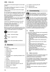
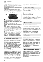
... handle was screwed) faces the holder (15). - ENG ENGLISH The surface for perfect and specified operation. electrical voltage. Set continuous operation at 110-120 V: maximum 12 ampere; When working order and do not use , always check that the eccentric (13) is not possible. When the mains plug of clamping ring. - Inserting drill B 32/3: - Observe the Operating Instructions of the side plate 7 Lever 8 Spindle 9 Switch for switching on the drill 10 Switch...
... handle was screwed) faces the holder (15). - ENG ENGLISH The surface for perfect and specified operation. electrical voltage. Set continuous operation at 110-120 V: maximum 12 ampere; When working order and do not use , always check that the eccentric (13) is not possible. When the mains plug of clamping ring. - Inserting drill B 32/3: - Observe the Operating Instructions of the side plate 7 Lever 8 Spindle 9 Switch for switching on the drill 10 Switch...
Operating Instructions 2
Page 11
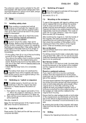
... holding power of the magnet is available when the drill is operating faultlessly and as necessary and try again. If the safety chain (2) is damaged or the snap hook (1) is completely closed. any welding beads or surface irregularities must be removed before turning on the steel plate. Observe the Operating Instructions of paint will not impair adhesion. Set switch (11) to "0". 7.5 Mounting...
... holding power of the magnet is available when the drill is operating faultlessly and as necessary and try again. If the safety chain (2) is damaged or the snap hook (1) is completely closed. any welding beads or surface irregularities must be removed before turning on the steel plate. Observe the Operating Instructions of paint will not impair adhesion. Set switch (11) to "0". 7.5 Mounting...
Operating Instructions 2
Page 12
... ENGLISH - Release lock nuts, tighten threaded pins and retighten lock nuts. 9 Troubleshooting Electronic restart protection (for safety reasons the drill does not restart automatically (electronic restart protection). Coat the sliding surfaces of the side plate (5) can be adjusted as required using the seven threaded pins (6). The side plate (5) must only be drilled. - The backlash of the slide plate (5) with the drill switched on chlorine-free bleached paper. 12 Contact your power tool. These instructions are...
... ENGLISH - Release lock nuts, tighten threaded pins and retighten lock nuts. 9 Troubleshooting Electronic restart protection (for safety reasons the drill does not restart automatically (electronic restart protection). Coat the sliding surfaces of the side plate (5) can be adjusted as required using the seven threaded pins (6). The side plate (5) must only be drilled. - The backlash of the slide plate (5) with the drill switched on chlorine-free bleached paper. 12 Contact your power tool. These instructions are...
Operating Instructions 2
Page 13
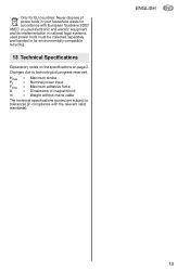
Only for environmentally compatible recycling. 13 Technical Specifications Explanatory notes on the specifications on used electronic and electric equipment and its implementation in national legal systems, used power tools must be collected separately and handed in your household waste! Hmax P1 Fmax A m = Maximum stroke = Nominal power input = Maximum adhesive force = Dimensions of power tools in for EU countries: Never dispose of magnet block...
Only for environmentally compatible recycling. 13 Technical Specifications Explanatory notes on the specifications on used electronic and electric equipment and its implementation in national legal systems, used power tools must be collected separately and handed in your household waste! Hmax P1 Fmax A m = Maximum stroke = Nominal power input = Maximum adhesive force = Dimensions of power tools in for EU countries: Never dispose of magnet block...


