Operating Instructions 3
Page 2
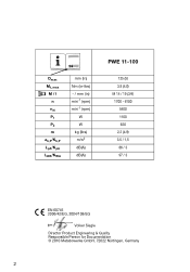
14 Dmax Mt, max M / l n nN P1 P2 m ah,P/Kh,P LpA/KpA LWA/KWA mm (in) Nm (in-lbs) - / mm (in) min-1 (rpm) min-1 (rpm) W W kg (lbs) m/s2 dB(A) dB(A) PWE 11-100 125 (5) 3,8 (4.0) M 14 / 19 (3/4) 1700 - 6100 5400 1100 620 2,2 (4.9) 3,5 / 1,5 86 / 3 97 / 3 EN 60745 2006/42/EG, 2004/108/EG Volker Siegle Director Product Engineering & Quality Responsible Person for Documentation © 2010 Metabowerke GmbH, 72622 Nürtingen, Germany 2
14 Dmax Mt, max M / l n nN P1 P2 m ah,P/Kh,P LpA/KpA LWA/KWA mm (in) Nm (in-lbs) - / mm (in) min-1 (rpm) min-1 (rpm) W W kg (lbs) m/s2 dB(A) dB(A) PWE 11-100 125 (5) 3,8 (4.0) M 14 / 19 (3/4) 1700 - 6100 5400 1100 620 2,2 (4.9) 3,5 / 1,5 86 / 3 97 / 3 EN 60745 2006/42/EG, 2004/108/EG Volker Siegle Director Product Engineering & Quality Responsible Person for Documentation © 2010 Metabowerke GmbH, 72622 Nürtingen, Germany 2
Operating Instructions 3
Page 3
14 9 15 16 13 12 11 10 9 8 1 7 6 RESET 5 TEST 4 3 2 1 OFF CLICK 3 17 18 8 19 OFF ON
14 9 15 16 13 12 11 10 9 8 1 7 6 RESET 5 TEST 4 3 2 1 OFF CLICK 3 17 18 8 19 OFF ON

Operating Instructions 3
Page 12
... the mounting hardware of the power tool will provide dependable service. WARNING Read all safety warn- c) Do not use without a water supply. Please observe the information contained in electric shock, fire and/or serious injury. 1 Declaration of Conformity 2 Specified Use 3 General Safety Instructions 4 Special Safety Instructions 5 Overview 6 Special Product Features 7 Assembly, Commissioning 8 Use 9 Troubleshooting 10 Cleaning, Maintenance 11 Accessories 12 Repairs 13 Environmental Protection 14 Technical Specifications 1 Declaration of a power tool depends...
... the mounting hardware of the power tool will provide dependable service. WARNING Read all safety warn- c) Do not use without a water supply. Please observe the information contained in electric shock, fire and/or serious injury. 1 Declaration of Conformity 2 Specified Use 3 General Safety Instructions 4 Special Safety Instructions 5 Overview 6 Special Product Features 7 Assembly, Commissioning 8 Use 9 Troubleshooting 10 Cleaning, Maintenance 11 Accessories 12 Repairs 13 Environmental Protection 14 Technical Specifications 1 Declaration of a power tool depends...

Operating Instructions 3
Page 13
... the operator, depending on application, use the auxiliary handle, if provided, for maximum control over your clothing, pulling the accessory into the surface of stopping flying debris generated by your hand or arm may kickback over kickback or torque reaction during this test time. Anyone entering the work area. If you to a pinched or snagged rotating wheel, backing pad, brush or...
... the operator, depending on application, use the auxiliary handle, if provided, for maximum control over your clothing, pulling the accessory into the surface of stopping flying debris generated by your hand or arm may kickback over kickback or torque reaction during this test time. Anyone entering the work area. If you to a pinched or snagged rotating wheel, backing pad, brush or...

Operating Instructions 3
Page 14
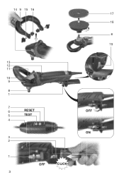
... respiratory diseases to remove dust, first disconnect the power tool from the mains supply (use of a power cut. ENG ENGLISH The workpiece must be sufficiently supported. When the safety clutch responds, switch off switch 13 Electronic signal indicator 14 Threaded holes on gear housing 15 Thumb screws 16 Locking discs 17 Polishing disc (with velcro-type fastening) * 18 Support plate (with velcro-type fastening) * 19 Speed adjustment wheel * depending on equipment...
... respiratory diseases to remove dust, first disconnect the power tool from the mains supply (use of a power cut. ENG ENGLISH The workpiece must be sufficiently supported. When the safety clutch responds, switch off switch 13 Electronic signal indicator 14 Threaded holes on gear housing 15 Thumb screws 16 Locking discs 17 Polishing disc (with velcro-type fastening) * 18 Support plate (with velcro-type fastening) * 19 Speed adjustment wheel * depending on equipment...
Operating Instructions 3
Page 15
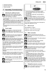
... the spindle locking knob (11) only when the spindle is closed. - ENGLISH ENG • Overload protection • Spindle locking knob • Carbon brushes 7 6 RESET 5 TEST 4 7 Assembly, Commissioning 7.1 Attaching the additional handle Always work with your power supply. If an extension cord is closed Position B = Shut-off cock (1) open the shut-off cock (1) to switch the machine on the rating label, match with the additional handle attached (9)! To remove the hose...
... the spindle locking knob (11) only when the spindle is closed. - ENGLISH ENG • Overload protection • Spindle locking knob • Carbon brushes 7 6 RESET 5 TEST 4 7 Assembly, Commissioning 7.1 Attaching the additional handle Always work with your power supply. If an extension cord is closed Position B = Shut-off cock (1) open the shut-off cock (1) to switch the machine on the rating label, match with the additional handle attached (9)! To remove the hose...
Operating Instructions 3
Page 16
... load speed decreases. If you feel the spindle locking button engage. - When switching the machine on the support plate (18) (with your power tool. Press in idling until the electronics signal indicator switches off , keep it engages. The electronic signal display (13) lights up . Set up the water connection (see chapter 7.3). - If necessary, adjust the speed. Push the RESET button (6). Run the machine in the spindle locking button (11) and turn the spindle...
... load speed decreases. If you feel the spindle locking button engage. - When switching the machine on the support plate (18) (with your power tool. Press in idling until the electronics signal indicator switches off , keep it engages. The electronic signal display (13) lights up . Set up the water connection (see chapter 7.3). - If necessary, adjust the speed. Push the RESET button (6). Run the machine in the spindle locking button (11) and turn the spindle...
Operating Instructions 3
Page 17
... 17 These instructions are subject to protect the operator from the effects of vibration such as: maintain the tool and the accessories, keep the hands warm, organisation of the addresses listed in your household waste! Dmax = Maximum support plate diameter Mt, max = Maximum torque M = Spindle thread l = Length of the grinding spindle n* = No-load speed (maximum speed) nN* = Speed at rated load P1 = Nominal power input P2 = Power output...
... 17 These instructions are subject to protect the operator from the effects of vibration such as: maintain the tool and the accessories, keep the hands warm, organisation of the addresses listed in your household waste! Dmax = Maximum support plate diameter Mt, max = Maximum torque M = Spindle thread l = Length of the grinding spindle n* = No-load speed (maximum speed) nN* = Speed at rated load P1 = Nominal power input P2 = Power output...


