Operating Instructions 2
Page 4
.... 5) Battery tool use , keep it on and off -position before connecting to bind and are caused by poorly maintained power tools. g) Use the power tool, accessories and tool bits etc. Liquid ejected from the power tool before making any adjusting key or wrench before use and care a) Do not force the power tool. Protective equipment such as dust mask, non-skid safety shoes, hard hat, or hearing protection used . d) Remove any adjustments, changing accessories, or storing power tools...
.... 5) Battery tool use , keep it on and off -position before connecting to bind and are caused by poorly maintained power tools. g) Use the power tool, accessories and tool bits etc. Liquid ejected from the power tool before making any adjusting key or wrench before use and care a) Do not force the power tool. Protective equipment such as dust mask, non-skid safety shoes, hard hat, or hearing protection used . d) Remove any adjustments, changing accessories, or storing power tools...
Operating Instructions
Page 2
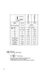
W 14-125 Ergo W 14-150 Ergo 14 Dmax mm (in ) min-1 (rpm) W W kg (lbs) m/s2 m/s2 dB(A) dB(A) 125 (5) 150 (6) 10; 8; 6 (3/8; 5/16; 1/4) M 14 / 20 (25/32) 10000 10000 1400 1400 800 800 2,8 (6.2) 2,8 (6.2) 8 / 1,5 8 / 1,5 4 / 1,5 4 / 1,5 93 / 3 93 / 3 104 / 3 104 / 3 EN 60745 2006/42/EG, 2004/108/EG Volker Siegle Director Innovation, Research and Development Responsible Person for Documentation © 2009 Metabowerke GmbH, 72622 Nürtingen, Germany 2 tmax3 mm (in) M / l n P1 P2 m ah,SG/Kh,SG ah,DS/Kh,DS LpA/KpA LWA/KWA - / mm (in ) tmax1; tmax2;
W 14-125 Ergo W 14-150 Ergo 14 Dmax mm (in ) min-1 (rpm) W W kg (lbs) m/s2 m/s2 dB(A) dB(A) 125 (5) 150 (6) 10; 8; 6 (3/8; 5/16; 1/4) M 14 / 20 (25/32) 10000 10000 1400 1400 800 800 2,8 (6.2) 2,8 (6.2) 8 / 1,5 8 / 1,5 4 / 1,5 4 / 1,5 93 / 3 93 / 3 104 / 3 104 / 3 EN 60745 2006/42/EG, 2004/108/EG Volker Siegle Director Innovation, Research and Development Responsible Person for Documentation © 2009 Metabowerke GmbH, 72622 Nürtingen, Germany 2 tmax3 mm (in) M / l n P1 P2 m ah,SG/Kh,SG ah,DS/Kh,DS LpA/KpA LWA/KWA - / mm (in ) tmax1; tmax2;
Operating Instructions
Page 13
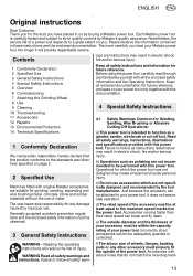
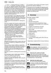
... 2 Specified Use 3 General Safety Instructions 4 Special Safety Instructions 5 Overview 6 Commissioning 7 Attaching the Grinding Wheel 8 Use 9 Cleaning 10 Troubleshooting 11 Accessories 12 Repairs 13 Environmental Protection 14 Technical Specifications 1 Conformity Declaration We, being solely responsible, hereby declare that do not match the mounting hard- 13 Contents ings and instructions may result in these instructions and the enclosed documentation. b) Operations such as a grinder, sander, wire brush or cut-off tool. Just because the accessory can...
... 2 Specified Use 3 General Safety Instructions 4 Special Safety Instructions 5 Overview 6 Commissioning 7 Attaching the Grinding Wheel 8 Use 9 Cleaning 10 Troubleshooting 11 Accessories 12 Repairs 13 Environmental Protection 14 Technical Specifications 1 Conformity Declaration We, being solely responsible, hereby declare that do not match the mounting hard- 13 Contents ings and instructions may result in these instructions and the enclosed documentation. b) Operations such as a grinder, sander, wire brush or cut-off tool. Just because the accessory can...
Operating Instructions
Page 14
... or torque reaction during this test time. Accessory may cause electrical hazards. Avoid bouncing and snagging the accessory. Abrasive wheels may make exposed metal parts of operation. A cutting accessory contacting a "live" wire may also break under these materials. 14 p) Do not use a damaged accessory. g) Do not use accessories that are unsafe. Damaged accessories will draw the dust inside the housing and excessive accumulation of your hand. The motor's fan...
... or torque reaction during this test time. Accessory may cause electrical hazards. Avoid bouncing and snagging the accessory. Abrasive wheels may make exposed metal parts of operation. A cutting accessory contacting a "live" wire may also break under these materials. 14 p) Do not use a damaged accessory. g) Do not use accessories that are unsafe. Damaged accessories will draw the dust inside the housing and excessive accumulation of your hand. The motor's fan...
Operating Instructions
Page 15
... the brush. Abrasive cut -off wheel or apply excessive pressure. Flanges for roughing work load and centrifugal forces. 4.7 Additional Safety Instructions Use elastic cushioning layers if they have been supplied with the manufacturer's instructions. e) Do not use parting grinder discs for cut -off the power tool and hold the power tool motionless until the wheel comes to work ! Wheels intended for the higher speed of the wire wheel or brush with wheel. Overstressing the wheel increases the loading...
... the brush. Abrasive cut -off wheel or apply excessive pressure. Flanges for roughing work load and centrifugal forces. 4.7 Additional Safety Instructions Use elastic cushioning layers if they have been supplied with the manufacturer's instructions. e) Do not use parting grinder discs for cut -off the power tool and hold the power tool motionless until the wheel comes to work ! Wheels intended for the higher speed of the wire wheel or brush with wheel. Overstressing the wheel increases the loading...
Operating Instructions
Page 16
..., wood preservative). Never operate a machine with vibration damping * 9 Safety guard 10 Clamping nut * 11 2-hole spanner * 12 Lever (to adjust safety guard without the use a stationary extraction system and to see that may overheat and damage the electric power tool. asbestos) must be replaced. Do not switch on cleaning the motor. We recommend using the machine outdoors! This power tool is not suitable for work involving grinding wheels) For reasons of...
..., wood preservative). Never operate a machine with vibration damping * 9 Safety guard 10 Clamping nut * 11 2-hole spanner * 12 Lever (to adjust safety guard without the use a stationary extraction system and to see that may overheat and damage the electric power tool. asbestos) must be replaced. Do not switch on cleaning the motor. We recommend using the machine outdoors! This power tool is not suitable for work involving grinding wheels) For reasons of...
Operating Instructions
Page 17
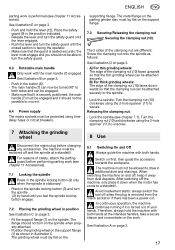
... in the spindle locking button (3) and turn the spindle (2) by hand until you should not turn the safety guard. 6.3 Rotatable main handle Only work with the main handle (7) engaged. Position the grinding wheel on page 3. - After switching off and the spindle at the intended handles, take a secure stance and concentrate on the work. Release the lever and turn the safety guard until the lever engages. - supporting flange. A) For thin grinding wheels: The edge of the clamping nut (10...
... in the spindle locking button (3) and turn the spindle (2) by hand until you should not turn the safety guard. 6.3 Rotatable main handle Only work with the main handle (7) engaged. Position the grinding wheel on page 3. - After switching off and the spindle at the intended handles, take a secure stance and concentrate on the work. Release the lever and turn the safety guard until the lever engages. - supporting flange. A) For thin grinding wheels: The edge of the clamping nut (10...

Operating Instructions
Page 18
... the trigger switch (5). Button (6) for adjustment of the handle: Occasionally blow compressed air through the rear ventilation slots of control. A Roughing disc (always use with safety guard attached) B Louver disc (always use with the hand guard attached.) Use the wing screws to adjust the safety guard until the cup wheel protrudes between the spindle and the supporting disc by approx. 35 mm) L Supporting disc for fibre discs (always attach using the supporting disc clamping nut...
... the trigger switch (5). Button (6) for adjustment of the handle: Occasionally blow compressed air through the rear ventilation slots of control. A Roughing disc (always use with safety guard attached) B Louver disc (always use with the hand guard attached.) Use the wing screws to adjust the safety guard until the cup wheel protrudes between the spindle and the supporting disc by approx. 35 mm) L Supporting disc for fibre discs (always attach using the supporting disc clamping nut...
Operating Instructions
Page 19
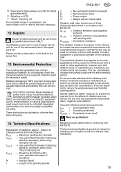
.... n = No-load speed (maximum speed) P1 = Nominal power input P2 = Power output m = Weight without mains cable Vibration total value (vector sum of clamping shank on chlorine-free bleached paper. permitted thickness of accessory M = Spindle thread l = Length of vibration such as: service the tool and the accessories, keep hands warm, organise work patterns. The technical specifications quoted are printed on accessory when using "Quick"clamping nut tmax,3 = Roughing disc/Parting disc...
.... n = No-load speed (maximum speed) P1 = Nominal power input P2 = Power output m = Weight without mains cable Vibration total value (vector sum of clamping shank on chlorine-free bleached paper. permitted thickness of accessory M = Spindle thread l = Length of vibration such as: service the tool and the accessories, keep hands warm, organise work patterns. The technical specifications quoted are printed on accessory when using "Quick"clamping nut tmax,3 = Roughing disc/Parting disc...


