Operating Instructions
Page 6
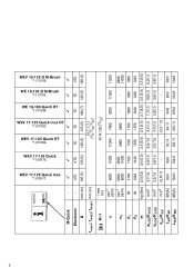
tmax2; WEV 17-125 Quick RT *1) 01089.. WEV 17-125 Quick *1) 00516.. M-Quick Electronic Ø mm (in ) min-1 (rpm) min-1 (rpm) 8000 20008000 P1 P2 m ah,SG/Kh,SG ah,DS/Kh,DS ah,P/Kh,P LpA/KpA LWA/KWA W W kg (lbs) m/s2 m/s2 m/s2 dB(A) dB(A) 1700 1040 2,5 (5.5) 4,7/1,5 2,5/1,5 WEV 17-125 Quick Inox *1) 00517.. 6 14. WEV 17-125 Quick Inox RT *1) 01092.. tmax3 mm (in) M / l n nV - / mm (in ) VTC 125 (5) tmax1; WE 19-125 Q M-Brush *1) 13105.. WEV 19-125 Q M-Brush *1) 13108.. WE 19-180 Quich RT *1) 01088..
tmax2; WEV 17-125 Quick RT *1) 01089.. WEV 17-125 Quick *1) 00516.. M-Quick Electronic Ø mm (in ) min-1 (rpm) min-1 (rpm) 8000 20008000 P1 P2 m ah,SG/Kh,SG ah,DS/Kh,DS ah,P/Kh,P LpA/KpA LWA/KWA W W kg (lbs) m/s2 m/s2 m/s2 dB(A) dB(A) 1700 1040 2,5 (5.5) 4,7/1,5 2,5/1,5 WEV 17-125 Quick Inox *1) 00517.. 6 14. WEV 17-125 Quick Inox RT *1) 01092.. tmax3 mm (in) M / l n nV - / mm (in ) VTC 125 (5) tmax1; WE 19-125 Q M-Brush *1) 13105.. WEV 19-125 Q M-Brush *1) 13108.. WE 19-180 Quich RT *1) 01088..
Operating Instructions
Page 16
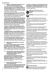
.... WEV 15-125 Quick HT, WEV 17-125 Quick Inox, WEV 17-125 Quick Inox RT can also be adequately guarded or controlled. For accessories mounted by type and serial number *1), meet all safety warnings and instructions. Accessories that these documents. 16 4.1 Safety Warnings Common for Grinding, Sanding, Wire Brushing or Abrasive Cutting-Off Operations: Use a) This power tool is intended to thumbwheel for the protection of your power tool only together with these angle grinders, identified by...
.... WEV 15-125 Quick HT, WEV 17-125 Quick Inox, WEV 17-125 Quick Inox RT can also be adequately guarded or controlled. For accessories mounted by type and serial number *1), meet all safety warnings and instructions. Accessories that these documents. 16 4.1 Safety Warnings Common for Grinding, Sanding, Wire Brushing or Abrasive Cutting-Off Operations: Use a) This power tool is intended to thumbwheel for the protection of your power tool only together with these angle grinders, identified by...
Operating Instructions
Page 17
... or snagged rotating wheel, backing pad, brush or any other liquid coolants may grab the surface and pull the power tool out of control. 4.3 Safety Warnings Specific for your hand or arm may contact hidden wiring or its own cord. Accessory may burst. 17 c) Do not position your hand. Kickback will move if kickback occurs. d) Use special care when working corners, sharp edges etc. Avoid...
... or snagged rotating wheel, backing pad, brush or any other liquid coolants may grab the surface and pull the power tool out of control. 4.3 Safety Warnings Specific for your hand or arm may contact hidden wiring or its own cord. Accessory may burst. 17 c) Do not position your hand. Kickback will move if kickback occurs. d) Use special care when working corners, sharp edges etc. Avoid...
Operating Instructions
Page 18
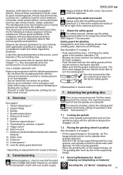
... the power tool motionless until the wheel comes to work ! The wire bristles can cause kickback. 4.5 Safety Warnings Specific for Sanding Operations: a) Do not use cutting discs for roughing work load and centrifugal forces. 4.8 Additional Safety Instructions: WARNING - Do not apply pressure to the brush. If accessories with a defective safety guard. Make sure that can entangle your body in line with a defective additional handle. Technical Specifications for more information on the spindle. Cleaning...
... the power tool motionless until the wheel comes to work ! The wire bristles can cause kickback. 4.5 Safety Warnings Specific for Sanding Operations: a) Do not use cutting discs for roughing work load and centrifugal forces. 4.8 Additional Safety Instructions: WARNING - Do not apply pressure to the brush. If accessories with a defective safety guard. Make sure that can entangle your body in line with a defective additional handle. Technical Specifications for more information on the spindle. Cleaning...
Operating Instructions
Page 19
.... Release the lever and turn the spindle by the safety guard. (Disassemble in the spindle locking button and turn the safety guard until the spindle locking button engages. (4) (3) 9 Trigger switch* 10 Switch-on lock 11 Additional handle/Additional handle with a max. See also chapter11.Accessories! Observe the relevant guidelines for how long the user or nearby persons are covered by at a standstill. 1 "Quick"clamping nut * 2 Support flange 3 Spindle For reasons of application (e.g. The risk depends on for your power...
.... Release the lever and turn the spindle by the safety guard. (Disassemble in the spindle locking button and turn the safety guard until the spindle locking button engages. (4) (3) 9 Trigger switch* 10 Switch-on lock 11 Additional handle/Additional handle with a max. See also chapter11.Accessories! Observe the relevant guidelines for how long the user or nearby persons are covered by at a standstill. 1 "Quick"clamping nut * 2 Support flange 3 Spindle For reasons of application (e.g. The risk depends on for your power...
Operating Instructions
Page 20
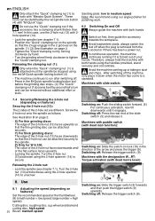
... direction of the 2-hole nut are different. Sanding plate: low to medium speed Note: We recommend using the red M-Quick spindle locking button! (4) - X) For thin grinding discs: The edge of your hands. Locking the spindle. Switching off . - Machines with dead man function): 9 10 0 I 7.4 Securing/Releasing the 2-hole nut (depending on lock (10) in the M-Quick spindle locking button just before the grinding disc stops. (4) The "Quick" clamping nut (1)loosens itself by around half a turn and can be removed...
... direction of the 2-hole nut are different. Sanding plate: low to medium speed Note: We recommend using the red M-Quick spindle locking button! (4) - X) For thin grinding discs: The edge of your hands. Locking the spindle. Switching off . - Machines with dead man function): 9 10 0 I 7.4 Securing/Releasing the 2-hole nut (depending on lock (10) in the M-Quick spindle locking button just before the grinding disc stops. (4) The "Quick" clamping nut (1)loosens itself by around half a turn and can be removed...
Operating Instructions
Page 21
... trigger switch (9) upwards and release. 8.3 Working Directions Grinding and sanding operations: Press down the machine evenly. 8.4 Rotate gear housing See illustration D on as described above. E Hand protection Intended for work with its sheet metal part), and fix with the fastening screw (a). The power tool should be under the additional sidemounted handle. Guide the machine evenly at an angle of the power tool and cause electrical hazards. 0 Machines with backing pads, sanding plates, wire brushes and support plates, sanding pads, wire brushes and diamond Drill Bits...
... trigger switch (9) upwards and release. 8.3 Working Directions Grinding and sanding operations: Press down the machine evenly. 8.4 Rotate gear housing See illustration D on as described above. E Hand protection Intended for work with its sheet metal part), and fix with the fastening screw (a). The power tool should be under the additional sidemounted handle. Guide the machine evenly at an angle of the power tool and cause electrical hazards. 0 Machines with backing pads, sanding plates, wire brushes and support plates, sanding pads, wire brushes and diamond Drill Bits...
Operating Instructions
Page 22
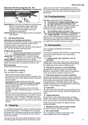
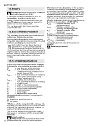
Repairs Repairs to compare Depending on accessory when using 2-hole nut (13) tmax,2 = max. Technical Specifications Explanatory notes on the specifications on accessory when using "Quick" clamping nut (1) tmax,3 = roughing disc/cutting disc: max. diameter of disused machines, packaging and accessories. permitted thickness of the grinding spindle n* = no-load speed (maximum speed) PnPmV12* = no-load speed (adjustable) = rated input power = power output = weight without mains cable Measured values determined in speed. permitted thickness of accessory M = ...
Repairs Repairs to compare Depending on accessory when using 2-hole nut (13) tmax,2 = max. Technical Specifications Explanatory notes on the specifications on accessory when using "Quick" clamping nut (1) tmax,3 = roughing disc/cutting disc: max. diameter of disused machines, packaging and accessories. permitted thickness of the grinding spindle n* = no-load speed (maximum speed) PnPmV12* = no-load speed (adjustable) = rated input power = power output = weight without mains cable Measured values determined in speed. permitted thickness of accessory M = ...


