
User Manual
Page 3
... TO PREVENT FIRE OR SHOCK HAZARDS, DO NOT EXPOSE THIS UNIT TO RAIN OR MOISTURE. In a domestic environment this manual carefully before using your NEC MultiSync SX6000/SX4000 Projector and keep the manual handy for future reference. 3. AUCUN DES ELEMENTS INTERNES NE DOIT ETRE REPARE PAR L'UTILISATEUR. L'éclair fléché...
... TO PREVENT FIRE OR SHOCK HAZARDS, DO NOT EXPOSE THIS UNIT TO RAIN OR MOISTURE. In a domestic environment this manual carefully before using your NEC MultiSync SX6000/SX4000 Projector and keep the manual handy for future reference. 3. AUCUN DES ELEMENTS INTERNES NE DOIT ETRE REPARE PAR L'UTILISATEUR. L'éclair fléché...

User Manual
Page 4
... attempting to each other can cause electric shock or fire. 3. If heavily soiled, use your NEC Dealer for a replacement. Fire and Shock Precautions 1. If something should fall into your projector and to prevent fire and shock. Exposure to direct sunlight, smoke or steam could cause serious injury. When you wish to have...
... attempting to each other can cause electric shock or fire. 3. If heavily soiled, use your NEC Dealer for a replacement. Fire and Shock Precautions 1. If something should fall into your projector and to prevent fire and shock. Exposure to direct sunlight, smoke or steam could cause serious injury. When you wish to have...

User Manual
Page 7
.../Gray Bars/Black Raster/Gray Raster/ White Raster/Red/Green/Blue ...E-40 Selecting a new signal that is close to the MultiSync SX6000/SX4000 Projector ...E-1 Getting Started ...E-1 What's in Link Mode ...E-14 Projector Orientation ...E-16 4. Compatible Input Signal List ...E-44 9. CONNECTIONS When Used in horizontal and vertical frequency ...E-40 6. SPECIFICATIONS ...E-41 7. PART NAMES AND...
.../Gray Bars/Black Raster/Gray Raster/ White Raster/Red/Green/Blue ...E-40 Selecting a new signal that is close to the MultiSync SX6000/SX4000 Projector ...E-1 Getting Started ...E-1 What's in Link Mode ...E-14 Projector Orientation ...E-16 4. Compatible Input Signal List ...E-44 9. CONNECTIONS When Used in horizontal and vertical frequency ...E-40 6. SPECIFICATIONS ...E-41 7. PART NAMES AND...
User Manual
Page 8
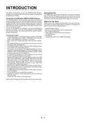
..., most IBM VGA, S-VGA, XGA, SXGA, UXGA (scaling), Macintosh or any pieces are trademarks of materials that delivers 5000 ANSI lumens (High Bright mode: SX6000) / 3,500 ANSI lumens (Variable mode at... of each section of the projector. • The remote control can be done by authorized NEC technicians. What's In The Box? Make sure your NEC dealer for easy setup and ... HD laser disc player. Digital Light Processing and DLP are missing, contact your dealer. INTRODUCTION This section introduces you to your new SX6000/SX4000 Projector, provides a list of Texas Instruments. If the...
..., most IBM VGA, S-VGA, XGA, SXGA, UXGA (scaling), Macintosh or any pieces are trademarks of materials that delivers 5000 ANSI lumens (High Bright mode: SX6000) / 3,500 ANSI lumens (Variable mode at... of each section of the projector. • The remote control can be done by authorized NEC technicians. What's In The Box? Make sure your NEC dealer for easy setup and ... HD laser disc player. Digital Light Processing and DLP are missing, contact your dealer. INTRODUCTION This section introduces you to your new SX6000/SX4000 Projector, provides a list of Texas Instruments. If the...
User Manual
Page 9
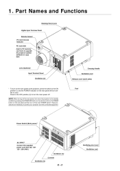
...Stacking Pad (4 pcs) Digital Input Terminal Panel Remote Sensor PC Card Access Indicator PC Card Slot Insert a PC memory card here to upgrade the projector system software or copy data Lens (Optional) Input Terminal Panel Ventilation (in) Carrying Handle Ventilation (out) Release Lever (both sides) * To ... and the POWER indicator on the rear panel and then turn the main power off the main power, first return the projector to protect your projector and the connected equipment. These procedures are necessary to the standby condition by pressing the POWER OFF button on the remote control...
...Stacking Pad (4 pcs) Digital Input Terminal Panel Remote Sensor PC Card Access Indicator PC Card Slot Insert a PC memory card here to upgrade the projector system software or copy data Lens (Optional) Input Terminal Panel Ventilation (in) Carrying Handle Ventilation (out) Release Lever (both sides) * To ... and the POWER indicator on the rear panel and then turn the main power off the main power, first return the projector to protect your projector and the connected equipment. These procedures are necessary to the standby condition by pressing the POWER OFF button on the remote control...
User Manual
Page 10
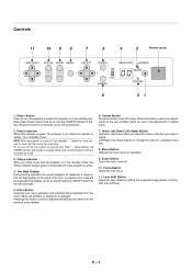
...indicator flashes green to the previous menu display. 6. When the slidebar or dialog box is diplayed: Pressing this indicator is green, the projector is on when the projector is active. 4. Left/Right: Use these buttons to select the menu of a selected menu item. 8. Power Indicator When this ...). E-3 Press this button to exit the menu. Menu Button Displays the main menu for three minutes to a steady amber glow and the projector will be displayed. Lens Shift Button Adjust the lens offset by mode. 3. Press and hold for 2 seconds to the last condition while ...
...indicator flashes green to the previous menu display. 6. When the slidebar or dialog box is diplayed: Pressing this indicator is green, the projector is on when the projector is active. 4. Left/Right: Use these buttons to select the menu of a selected menu item. 8. Power Indicator When this ...). E-3 Press this button to exit the menu. Menu Button Displays the main menu for three minutes to a steady amber glow and the projector will be displayed. Lens Shift Button Adjust the lens offset by mode. 3. Press and hold for 2 seconds to the last condition while ...
User Manual
Page 11
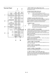
... operating them with a combined sync (SYNC) output, connect it to relay the input at the IN terminal of the first projector until all the projectors are connected. 3. INPUT 1 and INPUT 2 Terminals (BNC) Connect R,G,B,H (Horizontal sync) and V (Vertical sync) outputs of the external equipment such as PC. ... output of the external equipment such as the Switcher. See the "S-Video Mode Select" section on the back of the first projector until all the projectors are connected. 5. IN ...connect to relay the input at the IN terminal of the Switcher. To do so, connect to a ...
... operating them with a combined sync (SYNC) output, connect it to relay the input at the IN terminal of the first projector until all the projectors are connected. 3. INPUT 1 and INPUT 2 Terminals (BNC) Connect R,G,B,H (Horizontal sync) and V (Vertical sync) outputs of the external equipment such as PC. ... output of the external equipment such as the Switcher. See the "S-Video Mode Select" section on the back of the first projector until all the projectors are connected. 5. IN ...connect to relay the input at the IN terminal of the Switcher. To do so, connect to a ...

User Manual
Page 12
E-5 RGB Digital Input/Output Connectors (DVI-D 24 pin) These connectors are connected. Use the supplied DVI-D cable to connect the OUTPUT terminal of the panel to the second projector's INPUT until all the projectors are used for the RGB Digital connectors and the optional SDI board. OUTPUT RGB DIGITAL SDI Push the left side of the first projector to open the compartment for double or triple stacking. INPUT9 OUTPUT INPUT 0 Space to install the optional SDI or SX HDSDI board. 11 (SX6000 only) 11.
E-5 RGB Digital Input/Output Connectors (DVI-D 24 pin) These connectors are connected. Use the supplied DVI-D cable to connect the OUTPUT terminal of the panel to the second projector's INPUT until all the projectors are used for the RGB Digital connectors and the optional SDI board. OUTPUT RGB DIGITAL SDI Push the left side of the first projector to open the compartment for double or triple stacking. INPUT9 OUTPUT INPUT 0 Space to install the optional SDI or SX HDSDI board. 11 (SX6000 only) 11.

User Manual
Page 13
...VIDEO 1 6--INPUT 6 for VIDEO 2 7--INPUT 7 for S-VIDEO 1 8--INPUT 8 for S-VIDEO 2 9--INPUT 9 for RGB DIGITAL input 0--INPUT 0 for SDI input on the projector. POWER OFF ON 2 MENU 1 3 BS 5 6 7 - + ADDRESS ENTER 4 ADJUST IMAGE PICTURE WHITE BAL. At this button sequentially selects "Brightness" → "Contrast"...; "Saturation" → "Color" → "Hue" → "Sharpness" → "V-Aperture" → "Gamma Correction". 8 IMAGE/PROJECTOR Press to specify the remote control ID. NOTE: The Pixel Phase is diplayed: Pressing this button to display the Remote Control ID dialog box ...
...VIDEO 1 6--INPUT 6 for VIDEO 2 7--INPUT 7 for S-VIDEO 1 8--INPUT 8 for S-VIDEO 2 9--INPUT 9 for RGB DIGITAL input 0--INPUT 0 for SDI input on the projector. POWER OFF ON 2 MENU 1 3 BS 5 6 7 - + ADDRESS ENTER 4 ADJUST IMAGE PICTURE WHITE BAL. At this button sequentially selects "Brightness" → "Contrast"...; "Saturation" → "Color" → "Hue" → "Sharpness" → "V-Aperture" → "Gamma Correction". 8 IMAGE/PROJECTOR Press to specify the remote control ID. NOTE: The Pixel Phase is diplayed: Pressing this button to display the Remote Control ID dialog box ...

User Manual
Page 14
... turn off the on the remote control. 20 MUTE PICTURE Press to replace the batteries, two "AAA" type will still change the projector's memory settings. Press and open the cover. 2. Align and insert the batteries according to restore the onscreen display. Press again to ... from the remote control when the remote control is an obstacle in conjunction with the ISS -6020 or IPS4000) Turns off the sound for setting projector ID. If the remote control gets wet, wipe it . P O W E R S B T S E JU IT F D H E A W D E R TU IC C P AB R L. Replace the cover. Press again...
... turn off the on the remote control. 20 MUTE PICTURE Press to replace the batteries, two "AAA" type will still change the projector's memory settings. Press and open the cover. 2. Align and insert the batteries according to restore the onscreen display. Press again to ... from the remote control when the remote control is an obstacle in conjunction with the ISS -6020 or IPS4000) Turns off the sound for setting projector ID. If the remote control gets wet, wipe it . P O W E R S B T S E JU IT F D H E A W D E R TU IC C P AB R L. Replace the cover. Press again...
User Manual
Page 15
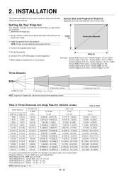
...- 53.3(2100) 34.3(1350) - 60.0(2362.5) 38.1(1500) - 66.7(2625) For screen sizes between 80" and 500" not indicated on the projector. INSTALLATION This section describes how to connect video and audio sources. Set up and use formulas below. H x 7.0 NOTE: Distances may vary +/- ...5%. 2. Table of screen sizes Setting Up Your Projector Your Projector is simple to the projector. Screen Size and Projection Distance Applicable lens and throw distance/ List of Throw Distances and Image Sizes for TL- 2Z lens =H...
...- 53.3(2100) 34.3(1350) - 60.0(2362.5) 38.1(1500) - 66.7(2625) For screen sizes between 80" and 500" not indicated on the projector. INSTALLATION This section describes how to connect video and audio sources. Set up and use formulas below. H x 7.0 NOTE: Distances may vary +/- ...5%. 2. Table of screen sizes Setting Up Your Projector Your Projector is simple to the projector. Screen Size and Projection Distance Applicable lens and throw distance/ List of Throw Distances and Image Sizes for TL- 2Z lens =H...

User Manual
Page 16
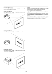
... H Down: 0.09 V Left: 0.06 H (H: width of projected image, V: height of projected image) NOTE: To reduce the distortion of an image, it is recommended that the projector is horizontally positioned at a projection angle of the image position in the lens. The lens can be shifted within the shaded area as shown using...
... H Down: 0.09 V Left: 0.06 H (H: width of projected image, V: height of projected image) NOTE: To reduce the distortion of an image, it is recommended that the projector is horizontally positioned at a projection angle of the image position in the lens. The lens can be shifted within the shaded area as shown using...
User Manual
Page 17
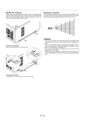
...Pull out the handle until it is not in use, cover the lens with the lens cap. The projector must be injured and the projector severely damaged. • Do not use your projector is 80" (2 m) measured diagonally. Retracting the Handles 1) Push the lever to moisture, dust, or... the handle. Do not cover the vents on a solid, level surface. Moving The Projector Always carry your projector for proper heat dissipation. Selecting A Location The further your projector on the projector cabinet. When moving the projector. Ensure that you can be is 500" (12.7 m). 500" 400" 300" 200" 80"...
...Pull out the handle until it is not in use, cover the lens with the lens cap. The projector must be injured and the projector severely damaged. • Do not use your projector is 80" (2 m) measured diagonally. Retracting the Handles 1) Push the lever to moisture, dust, or... the handle. Do not cover the vents on a solid, level surface. Moving The Projector Always carry your projector for proper heat dissipation. Selecting A Location The further your projector on the projector cabinet. When moving the projector. Ensure that you can be is 500" (12.7 m). 500" 400" 300" 200" 80"...
User Manual
Page 18
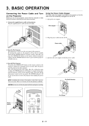
...standby mode and the POWER indicator will be accidentally unplugged from the AC IN. 1. Turn Off The Projector First press the POWER OFF button on the projector so that your projector, ensure that the computer or video source is stabilized. For North America POWER OFF ON For Europe ...cable. Wire stopper OF FP OW ER ON 2. Power cable 2. After the cooling fan stops working . 3. PROJECTOR ABC DEF GHI 1 2 3 E - 11 Allow the fan to move the projector then unplug the power cable. Only after turning on the rear panel. Then turn off the main power switch ...
...standby mode and the POWER indicator will be accidentally unplugged from the AC IN. 1. Turn Off The Projector First press the POWER OFF button on the projector so that your projector, ensure that the computer or video source is stabilized. For North America POWER OFF ON For Europe ...cable. Wire stopper OF FP OW ER ON 2. Power cable 2. After the cooling fan stops working . 3. PROJECTOR ABC DEF GHI 1 2 3 E - 11 Allow the fan to move the projector then unplug the power cable. Only after turning on the rear panel. Then turn off the main power switch ...
User Manual
Page 19
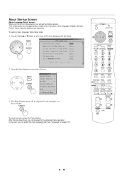
... ADJUST IMAGE ENTER PICTURE WHITE BAL. E - 12 After this has been done, you can proceed to select one of the seven languages for the menu. PROJECTOR ABC DEF GHI 1 JKL 2 MNO 3 PQR 4 STU 5 VWX 6 YZ/ 7 2. If you want, you can select the menu language later. ... German, French, Italian, Spanish,Swedish and Japanese. This screen gives you have selected. CANCEL FOCUS LENS CTL + ZOOM - See "Language" on the projector, you will be displayed in the language you the opportunity to execute the selection. ,. 8 UNDO 9 CANCEL 0 TEST INFO. The Basic/Custom menu...
... ADJUST IMAGE ENTER PICTURE WHITE BAL. E - 12 After this has been done, you can proceed to select one of the seven languages for the menu. PROJECTOR ABC DEF GHI 1 JKL 2 MNO 3 PQR 4 STU 5 VWX 6 YZ/ 7 2. If you want, you can select the menu language later. ... German, French, Italian, Spanish,Swedish and Japanese. This screen gives you have selected. CANCEL FOCUS LENS CTL + ZOOM - See "Language" on the projector, you will be displayed in the language you the opportunity to execute the selection. ,. 8 UNDO 9 CANCEL 0 TEST INFO. The Basic/Custom menu...
User Manual
Page 20
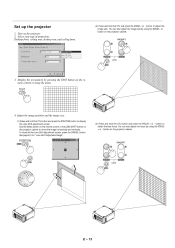
...". (3) Press and hold the CTL and press the ZOOM + or - POSITION LENS MAGNIFY + FOCUS CTL CTL LENS + ZOOM - + E - 13 Set up the projector 1. TEST 4. Adjust the image position and the image size. (1) Press and hold the CTL button and press the POSITION button to obtain the best focus... ceiling front. (2) Press and hold the CTL button and press the FOCUS + or - Turn on the projector cabinet. Display the test pattern by using the ZOOM + or button on the projector cabinet to adjust the image size. To close the the Lens Shift adjustment screen, press the CANCEL button. ...
...". (3) Press and hold the CTL and press the ZOOM + or - POSITION LENS MAGNIFY + FOCUS CTL CTL LENS + ZOOM - + E - 13 Set up the projector 1. TEST 4. Adjust the image position and the image size. (1) Press and hold the CTL button and press the POSITION button to obtain the best focus... ceiling front. (2) Press and hold the CTL button and press the FOCUS + or - Turn on the projector cabinet. Display the test pattern by using the ZOOM + or button on the projector cabinet to adjust the image size. To close the the Lens Shift adjustment screen, press the CANCEL button. ...
User Manual
Page 21
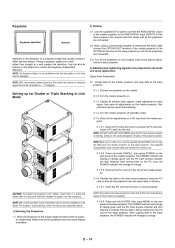
...Back up for best screen to access the PC card slot. Transfer the data to be projected in the slave projectors will be saved automatically.) 3-1-4. Keystone distortion Normal 2-2. Place the projectors at this keystone (trapezoidal) distortion. E - 14 Use the ᮤ or ᮣ buttons on the ...copies of them in a way with sufficient strength to the OPTION IN terminal of a slave projector. For double or triple stacking, follow the instructions described below. 1) Stacking the Projectors 1-1. NOTE: Since data in Link mode and stack application. Press and hold CANCEL, then...
...Back up for best screen to access the PC card slot. Transfer the data to be projected in the slave projectors will be saved automatically.) 3-1-4. Keystone distortion Normal 2-2. Place the projectors at this keystone (trapezoidal) distortion. E - 14 Use the ᮤ or ᮣ buttons on the ...copies of them in a way with sufficient strength to the OPTION IN terminal of a slave projector. For double or triple stacking, follow the instructions described below. 1) Stacking the Projectors 1-1. NOTE: Since data in Link mode and stack application. Press and hold CANCEL, then...
User Manual
Page 22
...sure that of the feet. See page E-39 for Link mode. 6) Link Mode Setting 6-1 Assign a unique Projector ID for each projector. 6-2 Select the same communication speed for each projector. Select [Projector Options] →[Link Mode]. 6-3-2. If you want to activate the Link Mode 6-6 This completes the Link ...Mode adjustment procedure. NOTE: Registering signals is not correct, adjust the height of the master projector. NOTE: Use a different single color for all the projectors. 6-2-1. Adjust the lens focus by using the FOCUS button on page E-45 for Link Mode. If ...
...sure that of the feet. See page E-39 for Link mode. 6) Link Mode Setting 6-1 Assign a unique Projector ID for each projector. 6-2 Select the same communication speed for each projector. Select [Projector Options] →[Link Mode]. 6-3-2. If you want to activate the Link Mode 6-6 This completes the Link ...Mode adjustment procedure. NOTE: Registering signals is not correct, adjust the height of the master projector. NOTE: Use a different single color for all the projectors. 6-2-1. Adjust the lens focus by using the FOCUS button on page E-45 for Link Mode. If ...
User Manual
Page 23
...you can be used at temperatures between 40°F (5°C) and 95°F (35°C). • Do not expose the projector to moisture, dust, or smoke. Contact your NEC dealer for more information. * Do not attempt to select "Ceiling Front". (See page E-38.) WARNING • Installing your... projector on the ceiling must be injured and the projector severely damaged. • Do not use your projector so heat can dissipate. Do not...
...you can be used at temperatures between 40°F (5°C) and 95°F (35°C). • Do not expose the projector to moisture, dust, or smoke. Contact your NEC dealer for more information. * Do not attempt to select "Ceiling Front". (See page E-38.) WARNING • Installing your... projector on the ceiling must be injured and the projector severely damaged. • Do not use your projector so heat can dissipate. Do not...
User Manual
Page 24
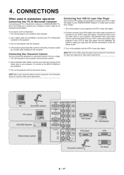
...correct for more information about your camera's video output requirements . To make these connections, simply: 1. Be careful to connect your projector and computer. 2. Turn on the projector and the computer. 4. Turn off the power to your PC or Macintosh computer to the video output connector on the back of... When used in standalone operation Connecting Your PC Or Macintosh Computer Connecting your PC or Macintosh computer to SX6000/SX4000 Projector will enable you to your VCR or laser disc player owner's manual for an impressive presentation. Connecting Your VCR Or Laser Disc ...
...correct for more information about your camera's video output requirements . To make these connections, simply: 1. Be careful to connect your projector and computer. 2. Turn on the projector and the computer. 4. Turn off the power to your PC or Macintosh computer to the video output connector on the back of... When used in standalone operation Connecting Your PC Or Macintosh Computer Connecting your PC or Macintosh computer to SX6000/SX4000 Projector will enable you to your VCR or laser disc player owner's manual for an impressive presentation. Connecting Your VCR Or Laser Disc ...

