Manual
Page 2
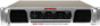
... internal low-pass filter and use the left and right main speakers AND your new 3WA-1700 amplifier has superior performance and greater flexibility than any other amplifier in its price range. noise-free on each channel; or to disable the internal ...Low Pass Filter can be adjusted from one of the NADY 3WA-1700 power amplifier - 3WA-1700 3-CHANNEL PROFESSIONAL POWER AMPLIFIER Congratulations on your choice in power amplifiers. A perfect amp for selecting NADY AUDIO as your choice of the finest power amplifiers on the market today. independent DC and thermal overload ...
... internal low-pass filter and use the left and right main speakers AND your new 3WA-1700 amplifier has superior performance and greater flexibility than any other amplifier in its price range. noise-free on each channel; or to disable the internal ...Low Pass Filter can be adjusted from one of the NADY 3WA-1700 power amplifier - 3WA-1700 3-CHANNEL PROFESSIONAL POWER AMPLIFIER Congratulations on your choice in power amplifiers. A perfect amp for selecting NADY AUDIO as your choice of the finest power amplifiers on the market today. independent DC and thermal overload ...

Manual
Page 3
... should always be connected to service the product beyond what is described in the operating instructions or as radiators, heat vents, or other devices (including amplifiers) that is maintained. 6. The power supply cord should be left plugged into , or liquid has been spilled onto the product. The product should : (1) be undamaged...
... should always be connected to service the product beyond what is described in the operating instructions or as radiators, heat vents, or other devices (including amplifiers) that is maintained. 6. The power supply cord should be left plugged into , or liquid has been spilled onto the product. The product should : (1) be undamaged...

Manual
Page 4
... CLIP (PEAK) LED INDICATORS These LEDs illuminate if the corresponding channel's output is turned "ON". 3. When either the power amplifier's level controls or reduce the output level of clipping. SIGNAL LED INDICATORS These LEDs illuminate to verify that they remain on more... monitor the clipping LEDs to excessive clipping. This can cause damage to excessive clipping. The actual voltage gain is shown in excess of the amplifier. 6. If the output connections are correct. A momentary muting is DC voltage at levels in dB. SUBWOOFER LEVEL CONTROL This controls the level...
... CLIP (PEAK) LED INDICATORS These LEDs illuminate if the corresponding channel's output is turned "ON". 3. When either the power amplifier's level controls or reduce the output level of clipping. SIGNAL LED INDICATORS These LEDs illuminate to verify that they remain on more... monitor the clipping LEDs to excessive clipping. This can cause damage to excessive clipping. The actual voltage gain is shown in excess of the amplifier. 6. If the output connections are correct. A momentary muting is DC voltage at levels in dB. SUBWOOFER LEVEL CONTROL This controls the level...

Manual
Page 5
... connecting either the 1/4" jack or the XLR jack to avoid damage. Speaker power ratings (in the following SPEAKER CONNECTIONS section on page 7 of the amplifier to the Subwoofer output. FANS The four variable-speed fans adjust speed automatically to pass full-range signals for the subwoofer. CONTROLS AND CONNECTIONS BACK... in excess of clipping can handle the rated output power to the input jack of cut filter for each channel, you can cause the amplifier to overload the amplifier. Never use at 30Hz with 12dB/octave of another amplifier by the Nady Service Department. 5
... connecting either the 1/4" jack or the XLR jack to avoid damage. Speaker power ratings (in the following SPEAKER CONNECTIONS section on page 7 of the amplifier to the Subwoofer output. FANS The four variable-speed fans adjust speed automatically to pass full-range signals for the subwoofer. CONTROLS AND CONNECTIONS BACK... in excess of clipping can handle the rated output power to the input jack of cut filter for each channel, you can cause the amplifier to overload the amplifier. Never use at 30Hz with 12dB/octave of another amplifier by the Nady Service Department. 5
Manual
Page 6
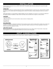
...well as "stack" mounting without a cabinet. I N S TA L L AT I O N To ensure years of enjoyment from your NADY AUDIO 3WA-1700 amplifier, please read and understand this manual thoroughly before using your unit, carefully examine the packaging and all contents for any signs of physical damage that... For best results, in a timely manner.) CONTENTS • Instruction manual • 3WA-1700 (verify that may have occurred in transit. (Note: Nady Systems is damaged, do not return to us, but notify your amplifier into a sound system. 6 Before installing and using the unit. Use 4 screws and...
...well as "stack" mounting without a cabinet. I N S TA L L AT I O N To ensure years of enjoyment from your NADY AUDIO 3WA-1700 amplifier, please read and understand this manual thoroughly before using your unit, carefully examine the packaging and all contents for any signs of physical damage that... For best results, in a timely manner.) CONTENTS • Instruction manual • 3WA-1700 (verify that may have occurred in transit. (Note: Nady Systems is damaged, do not return to us, but notify your amplifier into a sound system. 6 Before installing and using the unit. Use 4 screws and...

Manual
Page 7
... Filter/Source switch to find the setting that delivers the best sound from your crossover into a sound system. Turn off the amplifier power switch before making any connections. (Note: Nady Systems assumes no liability for damaged speakers resulting from your mixer into the Subwoofer input. 3. SPEAKER CONNECTIONS The following instructions describe the...
... Filter/Source switch to find the setting that delivers the best sound from your crossover into a sound system. Turn off the amplifier power switch before making any connections. (Note: Nady Systems assumes no liability for damaged speakers resulting from your mixer into the Subwoofer input. 3. SPEAKER CONNECTIONS The following instructions describe the...
Manual
Page 8
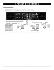
Input Monitor or Aux full-range signal from your crossover into the Subwoofer input. 3. AUX SEND/ MONITOR L R 4Ω min + - 4Ω min + - 8Ω 8Ω R 8Ω 8Ω MONITORS SOUND REINFORCEMENT (Note: Do not connect a speaker load less than 4Ω to OFF. SPEAKER CONNECTIONS • Mains & Monitor Mode 1. Set the Filter/Source switch to either channel as it can damage your mixer into Channels 1 and 2. 2. Input main Left and Right signals from your amplifier.) 4Ω min + - 8Ω 8Ω L 8
Input Monitor or Aux full-range signal from your crossover into the Subwoofer input. 3. AUX SEND/ MONITOR L R 4Ω min + - 4Ω min + - 8Ω 8Ω R 8Ω 8Ω MONITORS SOUND REINFORCEMENT (Note: Do not connect a speaker load less than 4Ω to OFF. SPEAKER CONNECTIONS • Mains & Monitor Mode 1. Set the Filter/Source switch to either channel as it can damage your mixer into Channels 1 and 2. 2. Input main Left and Right signals from your amplifier.) 4Ω min + - 8Ω 8Ω L 8
Manual
Page 9
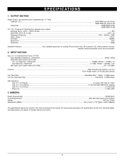
... - 400Hz @ 8Ω)...> 250 Slew Rate (1KHz @ 2 x 4Ω) ...6.5V / uS Frequency Response ...10Hz ~ 50KHz (- 2dB) THD + Noise...0.04% S/N Ratio ...- 86dBm Noise Floor ...3mV Total Gain ...40dB Amplifier Protection Four variable speed fans for this unit, including design and appearance, are correct at 110mV Sub, Ch 1 & 2 Clipping ...3 x red LED light 3dB before clipping...
... - 400Hz @ 8Ω)...> 250 Slew Rate (1KHz @ 2 x 4Ω) ...6.5V / uS Frequency Response ...10Hz ~ 50KHz (- 2dB) THD + Noise...0.04% S/N Ratio ...- 86dBm Noise Floor ...3mV Total Gain ...40dB Amplifier Protection Four variable speed fans for this unit, including design and appearance, are correct at 110mV Sub, Ch 1 & 2 Clipping ...3 x red LED light 3dB before clipping...