Manual
Page 2
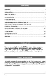
...‑step guide to operation of your Enc-DUET. 2 CONTENTS CONTENTS ...2 INTRODUCTION 2 USING THIS MANUAL 2 SYSTEM FEATURES 3 ENC-DUET RECEIVER 4 WHT HANDHELD MICROPHONE TRANSMITTER 7 WLT LAVALIER/LAPEL OR HEADWORN MICROPHONE BODYPACK TRANSMITTER 9 WGT INSTRUMENT BODYPACK TRANSMITTER 11 SPECIFICATIONS 13 SERVICE INFORMATION 14 WARRANTY 15 INTRODUCTION Thank you for choosing the Nady Enc-DUET dual receiver wireless microphone system, we know you may have about the operation and servicing of the...
...‑step guide to operation of your Enc-DUET. 2 CONTENTS CONTENTS ...2 INTRODUCTION 2 USING THIS MANUAL 2 SYSTEM FEATURES 3 ENC-DUET RECEIVER 4 WHT HANDHELD MICROPHONE TRANSMITTER 7 WLT LAVALIER/LAPEL OR HEADWORN MICROPHONE BODYPACK TRANSMITTER 9 WGT INSTRUMENT BODYPACK TRANSMITTER 11 SPECIFICATIONS 13 SERVICE INFORMATION 14 WARRANTY 15 INTRODUCTION Thank you for choosing the Nady Enc-DUET dual receiver wireless microphone system, we know you may have about the operation and servicing of the...
Manual
Page 3
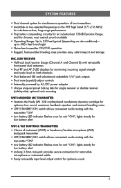
lights steady for low battery alert • Locking 3.5mm mini-jack provides secure connection for removable microphone or instrument cable • Easily accessible input level adjust control for unit "ON"; up to 250 feet typical (depending on both channels • Dual balanced XLR and unbalanced adjustable 1/4" jack outputs • Dual mute (squelch) adjust controls • Externally powered by AC/DC power adapter • Unique snap-out panel locking tabs for single receiver or...
lights steady for low battery alert • Locking 3.5mm mini-jack provides secure connection for removable microphone or instrument cable • Easily accessible input level adjust control for unit "ON"; up to 250 feet typical (depending on both channels • Dual balanced XLR and unbalanced adjustable 1/4" jack outputs • Dual mute (squelch) adjust controls • Externally powered by AC/DC power adapter • Unique snap-out panel locking tabs for single receiver or...

Manual
Page 4
... squelch control for Channel A and Channel B. These should move closer to the receiver to the factory preset minimum RF level. ENC DUET RECEIVER 1. this could degrade the performance of the receiver. However, in areas of the receiver's 5 LED RF LEVEL DISPLAYS (4) for that channel transmitter is properly adjusted, the RF LEVEL LED displays will reduce the range, but yield a quieter mute (squelch) function. Turning the squelch control too far clockwise will only light...
... squelch control for Channel A and Channel B. These should move closer to the receiver to the factory preset minimum RF level. ENC DUET RECEIVER 1. this could degrade the performance of the receiver. However, in areas of the receiver's 5 LED RF LEVEL DISPLAYS (4) for that channel transmitter is properly adjusted, the RF LEVEL LED displays will reduce the range, but yield a quieter mute (squelch) function. Turning the squelch control too far clockwise will only light...

Manual
Page 5
... simultaneously by the rear panel VOLUME CONTROLS (6) for your mixer or amp. 5 This setting is turned OFF before plugging in the A + B UNBALANCED OUTPUT JACK (13) on the input of the mixer is roughly equivalent to a direct instrument cord connection. Microphone Connection (using the WGT instrument transmitter) Insert an audio cord with the receiver volume controls. Connecting the Audio Output The Enc-DUET receiver provides both channels with the receiver volume at the factory and are set at the minimum level before making connection to , which...
... simultaneously by the rear panel VOLUME CONTROLS (6) for your mixer or amp. 5 This setting is turned OFF before plugging in the A + B UNBALANCED OUTPUT JACK (13) on the input of the mixer is roughly equivalent to a direct instrument cord connection. Microphone Connection (using the WGT instrument transmitter) Insert an audio cord with the receiver volume controls. Connecting the Audio Output The Enc-DUET receiver provides both channels with the receiver volume at the factory and are set at the minimum level before making connection to , which...

Manual
Page 7
... as per the Audio Output Microphone Connection section of the RF LEVEL DISPLAY LEDs (4) on the Enc-DUET receiver should be lit, indicating a received signal from the microphone until the red LED indicator only flickers on continuously, it means the signal is too loud and there is now ready to protect it is screwed on and off during use . 3. The AF LEVEL LED DISPLAY (5) on the mic element at...
... as per the Audio Output Microphone Connection section of the RF LEVEL DISPLAY LEDs (4) on the Enc-DUET receiver should be lit, indicating a received signal from the microphone until the red LED indicator only flickers on continuously, it means the signal is too loud and there is now ready to protect it is screwed on and off during use . 3. The AF LEVEL LED DISPLAY (5) on the mic element at...

Manual
Page 9
... the Enc-DUET receiver should be lit, indicating a received signal from all input signals. To secure the connection, turn the metal slip ring on the plug clockwise to your clothes. To use . In the case of the mic. When ready to speak, slide the transmitter switch to the ON position and adjust the volume of the receiver as handheld or headworn mics that are farther from the sound source...
... the Enc-DUET receiver should be lit, indicating a received signal from all input signals. To secure the connection, turn the metal slip ring on the plug clockwise to your clothes. To use . In the case of the mic. When ready to speak, slide the transmitter switch to the ON position and adjust the volume of the receiver as handheld or headworn mics that are farther from the sound source...
Manual
Page 10
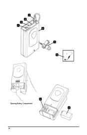
24 29 28 27 LOW MIC BAT HI OFF/STANDBY/ON 22 25 26 22 Opening Battery Compartment 23 10
24 29 28 27 LOW MIC BAT HI OFF/STANDBY/ON 22 25 26 22 Opening Battery Compartment 23 10

Manual
Page 11
... CORD (35) has a factory installed capacitor inside the 1/4" plug. Set for maximum range. The AF LEVEL LED DISPLAY (5) on continuously, turn the metal slip ring on the plug clockwise to your equipment still give a single quick flash, indicating usable battery strength. Turn on the WGT by turning the control with a fresh one. 3. However, for ultra high‑gain instrument sources such as per the Audio Output Instrument Connections...
... CORD (35) has a factory installed capacitor inside the 1/4" plug. Set for maximum range. The AF LEVEL LED DISPLAY (5) on continuously, turn the metal slip ring on the plug clockwise to your equipment still give a single quick flash, indicating usable battery strength. Turn on the WGT by turning the control with a fresh one. 3. However, for ultra high‑gain instrument sources such as per the Audio Output Instrument Connections...

Manual
Page 13
... connecting to 250 ft. typical (depending on site conditions); up to 500+ feet optimum line-of-sight ENC-DUET RECEIVER Reception Mode Controls Connectors LED Indicators Dimensions (Max.) Weight Power Requirements Antenna Dual receivers (Channel A and Channel B) Power ON/OFF, dual volume and mute controls (one each, Ch A/B) Dual balanced XLR and unbalanced adjustable 1/4" audio out jacks (Ch A & B mixed), 2.1mm barrel-type DC input jack Power ON, Dual 5-LED RF & AF level displays...
... connecting to 250 ft. typical (depending on site conditions); up to 500+ feet optimum line-of-sight ENC-DUET RECEIVER Reception Mode Controls Connectors LED Indicators Dimensions (Max.) Weight Power Requirements Antenna Dual receivers (Channel A and Channel B) Power ON/OFF, dual volume and mute controls (one each, Ch A/B) Dual balanced XLR and unbalanced adjustable 1/4" audio out jacks (Ch A & B mixed), 2.1mm barrel-type DC input jack Power ON, Dual 5-LED RF & AF level displays...

Manual
Page 14
...credit card) per instructions by the Nady Service Department. Ship your system, please refer to the Support page at (510) 652-2411 to obtain a Return Authorization (R/A) Number and service quote (if out of the problem you are returning. If you are experiencing. SERVICE INFORMATION In the ...Number is out of the package that you purchased this unit yourself as it can be dangerous and will also void the warranty. 14 For service of a unit under warranty, please follow the instructions in your country through the dealer/store from which you are experiencing operational problems...
...credit card) per instructions by the Nady Service Department. Ship your system, please refer to the Support page at (510) 652-2411 to obtain a Return Authorization (R/A) Number and service quote (if out of the problem you are returning. If you are experiencing. SERVICE INFORMATION In the ...Number is out of the package that you purchased this unit yourself as it can be dangerous and will also void the warranty. 14 For service of a unit under warranty, please follow the instructions in your country through the dealer/store from which you are experiencing operational problems...

Manual
Page 15
... responsible, for repair. warrants to Nady Systems, 6701 Shellmound Street, Emeryville, CA, 94608, freight pre-paid. To the extent permitted by abuse, neglect, accident, failure to connect or operate the unit in lieu of servicing your bill of sale) or Nady cannot be made against the shipping company by the shipper (Nady Systems is free from any Nady serial number has been...
... responsible, for repair. warrants to Nady Systems, 6701 Shellmound Street, Emeryville, CA, 94608, freight pre-paid. To the extent permitted by abuse, neglect, accident, failure to connect or operate the unit in lieu of servicing your bill of sale) or Nady cannot be made against the shipping company by the shipper (Nady Systems is free from any Nady serial number has been...
Manual
Page 16
Nady Wireless Systems are type accepted under FCC rules parts 90, 74 and 15. The device complies with RSS-210 of Industry & Science Canada. Operation is subject to the following two conditions: (1) this device may not cause harmful interference and (2) this device must accept any interference received, including interference that may cause undesired operation. 6701 Shellmound Street | Emeryville, CA USA 94608 T 510.652.2411 | F 510.652.5075 | www.nady.com
Nady Wireless Systems are type accepted under FCC rules parts 90, 74 and 15. The device complies with RSS-210 of Industry & Science Canada. Operation is subject to the following two conditions: (1) this device may not cause harmful interference and (2) this device must accept any interference received, including interference that may cause undesired operation. 6701 Shellmound Street | Emeryville, CA USA 94608 T 510.652.2411 | F 510.652.5075 | www.nady.com


