
Manual
Page 1
Instructions for use with any of these transmitters MGT-16 SYSTEM MHT-16 SYSTEM LINK-16 SYSTEM WHM-16 SYSTEM MH-16 MT-16A MT-16R LK-16 WH-16
Instructions for use with any of these transmitters MGT-16 SYSTEM MHT-16 SYSTEM LINK-16 SYSTEM WHM-16 SYSTEM MH-16 MT-16A MT-16R LK-16 WH-16

Manual
Page 2
... 2 Using this Manual 2 System Features (MGT-16/MHT-16/LINK-16/WHM-16 3 Quick User Controls/Connections Guide 4 MGT-16 Wireless Instrument Receiver 4 MT-16A/R Instrument Transmitter 6 MH-16 Horn Instrument Transmitter 7 LK-16 Snap-On Transmitter 8 WH-16 Head-Worn Transmitter 9 System Operation 10 MGT-16 Wireless Receiver 10 MT-16A/R, MH-16, LK-16, WH-16 Transmitters 11 Miscellaneous Tips 14 Cautions and Troubleshooting 15 MGT-16 System DIP-Switch Frequency Selection Chart 16 Specifications 17 Servicing 18...
... 2 Using this Manual 2 System Features (MGT-16/MHT-16/LINK-16/WHM-16 3 Quick User Controls/Connections Guide 4 MGT-16 Wireless Instrument Receiver 4 MT-16A/R Instrument Transmitter 6 MH-16 Horn Instrument Transmitter 7 LK-16 Snap-On Transmitter 8 WH-16 Head-Worn Transmitter 9 System Operation 10 MGT-16 Wireless Receiver 10 MT-16A/R, MH-16, LK-16, WH-16 Transmitters 11 Miscellaneous Tips 14 Cautions and Troubleshooting 15 MGT-16 System DIP-Switch Frequency Selection Chart 16 Specifications 17 Servicing 18...

Manual
Page 3
...;" line output plug • Power On/Off/Mute switch; Power/Low Battery LED indicators; DIP-switch channel selection with receiver for instant setup • Power On/Off switch; Power/Low Battery LED indicators; System Features MGT-16 Systems • 16 user-selectable UHF PLL frequencies for interference-free operation • Up to 250' operating range, line-of two transmitter housings- Volume Control; internal audio level control trim-pot • External flexible wire antenna LK-16 Snap-On Transmitter • Female XLR input connector...
...;" line output plug • Power On/Off/Mute switch; Power/Low Battery LED indicators; DIP-switch channel selection with receiver for instant setup • Power On/Off switch; Power/Low Battery LED indicators; System Features MGT-16 Systems • 16 user-selectable UHF PLL frequencies for interference-free operation • Up to 250' operating range, line-of two transmitter housings- Volume Control; internal audio level control trim-pot • External flexible wire antenna LK-16 Snap-On Transmitter • Female XLR input connector...

Manual
Page 5
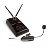
... a direct instrument-to-cord-to-amp connection 4. Controls the mute level for the receiver-turn counter-clockwise for best reception 10. ASC™ IR SYNC BUTTON Press to make the IR link download the receiver's selected frequency to release hinged door 7. AUDIO OUTPUT JACK For connecting audio cable 8. AA BATTERIES Two required for powering receiver 9. ASC™ IR SYNC INFRARED LED WINDOW For downloading selected Channel (Frequency) to achieve desired setting. 14. Note: Set control carefully. POWER SWITCH Select OFF/MUTE/ON (MUTE=power On, audio output...
... a direct instrument-to-cord-to-amp connection 4. Controls the mute level for the receiver-turn counter-clockwise for best reception 10. ASC™ IR SYNC BUTTON Press to make the IR link download the receiver's selected frequency to release hinged door 7. AUDIO OUTPUT JACK For connecting audio cable 8. AA BATTERIES Two required for powering receiver 9. ASC™ IR SYNC INFRARED LED WINDOW For downloading selected Channel (Frequency) to achieve desired setting. 14. Note: Set control carefully. POWER SWITCH Select OFF/MUTE/ON (MUTE=power On, audio output...

Manual
Page 6
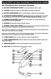
... sensor for higher level 19 audio input signals 19. INPUT ¼" PLUG Connect directly intoguitar/bass output jack 20. ANTENNA Permanently attached flexible antenna 25 25. POWER & LOW BATTERY LED Flashes once at power up to the TX. If trim-pot is turned past minimum 26 and maximum adjustment points it may need to be done only in rare cases as factory level setting is to the RX during IR frequency download 17 21...
... sensor for higher level 19 audio input signals 19. INPUT ¼" PLUG Connect directly intoguitar/bass output jack 20. ANTENNA Permanently attached flexible antenna 25 25. POWER & LOW BATTERY LED Flashes once at power up to the TX. If trim-pot is turned past minimum 26 and maximum adjustment points it may need to be done only in rare cases as factory level setting is to the RX during IR frequency download 17 21...
Manual
Page 7
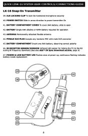
... bell of horn's sound 7 Quick MHT-16 User Controls/Connections Guide MH-16 Saxophone (Horn) Instrument Transmitter 28. BATTERY COMPARTMENT Insert one AAA battery, observing correct polarity 31. POWER SWITCH Slide in rare cases as factory level setting is turned past minimum and maximum adjustment points it may need to achieve desired setting. 35. If trim-pot is already optimized for higher level audio input signals 37. INPUT MIC For unidirectional pickup...
... bell of horn's sound 7 Quick MHT-16 User Controls/Connections Guide MH-16 Saxophone (Horn) Instrument Transmitter 28. BATTERY COMPARTMENT Insert one AAA battery, observing correct polarity 31. POWER SWITCH Slide in rare cases as factory level setting is turned past minimum and maximum adjustment points it may need to achieve desired setting. 35. If trim-pot is already optimized for higher level audio input signals 37. INPUT MIC For unidirectional pickup...
Manual
Page 8
... battery, observing correct polarity 46. QUICK LINK-16 SYSTEM USER CONTROLS/CONNECTIONS GUIDE LK-16 Snap-On Transmitter 39. ANTENNA Permanently attached flexible antenna 44. POWER & LOW BATTERY LED Flashes once at power up, continuous flashing indicates battery needs replacement 8 XLR LOCKING CLIP To lock the hardwired microphone securely 40. POWER SWITCH Slide in arrow direction to open 42. IR RECEPTOR SENSOR/WINDOW Infrared LED sensor for operation 43.
... battery, observing correct polarity 46. QUICK LINK-16 SYSTEM USER CONTROLS/CONNECTIONS GUIDE LK-16 Snap-On Transmitter 39. ANTENNA Permanently attached flexible antenna 44. POWER & LOW BATTERY LED Flashes once at power up, continuous flashing indicates battery needs replacement 8 XLR LOCKING CLIP To lock the hardwired microphone securely 40. POWER SWITCH Slide in arrow direction to open 42. IR RECEPTOR SENSOR/WINDOW Infrared LED sensor for operation 43.

Manual
Page 9
.... IR RECEPTOR SENSOR/WINDOW Infrared LED sensor for operation 52. BATTERY Single AAA alkaline or NiMH battery required for linking the TX to the RX during IR frequency download (See also ASCTM IR Sync Download section, page 6) AAA 9 INPUT MIC Unidirectional pickup for vocals 54. QUICK WHM-16 USER CONTROLS/CONNECTORS GUIDE WH-16 Head-Worn Transmitter 48. BATTERY COMPARTMENT Insert one...
.... IR RECEPTOR SENSOR/WINDOW Infrared LED sensor for operation 52. BATTERY Single AAA alkaline or NiMH battery required for linking the TX to the RX during IR frequency download (See also ASCTM IR Sync Download section, page 6) AAA 9 INPUT MIC Unidirectional pickup for vocals 54. QUICK WHM-16 USER CONTROLS/CONNECTORS GUIDE WH-16 Head-Worn Transmitter 48. BATTERY COMPARTMENT Insert one...

Manual
Page 10
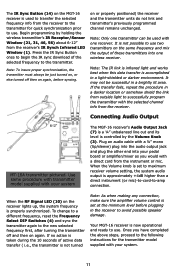
... areas of use for normal operation (receiver On and audio un‑muted). The Frequency Select DIP Switches (4) are used , the installed batteries are automatically disconnected internally and are now too low and should be downloaded to the transmitter to stop the flickering. A range walk test will also yield a quieter mute function, which the RF Signal LED (10) remains on while your application. Note: Set controls carefully...
... areas of use for normal operation (receiver On and audio un‑muted). The Frequency Select DIP Switches (4) are used , the installed batteries are automatically disconnected internally and are now too low and should be downloaded to the transmitter to stop the flickering. A range walk test will also yield a quieter mute function, which the RF Signal LED (10) remains on while your application. Note: Set controls carefully...
Manual
Page 11
... frequency, reset the Frequency Select DIP Switches (4) and sync the transmitter again to the new selected frequency first, after turning the transmitter off then on the same frequency and mix the output of these transmitters into your system The MGT-16 receiver's Audio Output Jack (7) is a ¼" unbalanced line out and its level is approximately +4dB higher than a direct instrument (or mic)-to-cord-to successfully program the transmitter with the selected channel...
... frequency, reset the Frequency Select DIP Switches (4) and sync the transmitter again to the new selected frequency first, after turning the transmitter off then on the same frequency and mix the output of these transmitters into your system The MGT-16 receiver's Audio Output Jack (7) is a ¼" unbalanced line out and its level is approximately +4dB higher than a direct instrument (or mic)-to-cord-to successfully program the transmitter with the selected channel...

Manual
Page 12
... setting for high-input signal adjustment- The Audio Level Adjust is factory set the audio deviation level. As the batteries weaken, the Low Battery Indicator will flash to warn that the battery level is too low and should be off , slide the power switch opposite direction, and the receiver RF Signal LED (10) should be replaced after six hours of operation, but raising distortion). To turn the transmitter off , slide the Power Switch in the direction...
... setting for high-input signal adjustment- The Audio Level Adjust is factory set the audio deviation level. As the batteries weaken, the Low Battery Indicator will flash to warn that the battery level is too low and should be off , slide the power switch opposite direction, and the receiver RF Signal LED (10) should be replaced after six hours of operation, but raising distortion). To turn the transmitter off , slide the Power Switch in the direction...

Manual
Page 13
... the direction of the selected frequency to the Selected Channel Before beginning operation, the transmitter must have a fixed input level. Operating the Transmitter (MT-16A/R, MH-16, LK-16, or WH-16) During normal operation with the selected frequency from the receiver's IR Synch Window. When programming is not possible. Press the IR Sync Button (14) on the head. When ready to play , slide the Power Switch (17, 35, 40, or 48) to use...
... the direction of the selected frequency to the Selected Channel Before beginning operation, the transmitter must have a fixed input level. Operating the Transmitter (MT-16A/R, MH-16, LK-16, or WH-16) During normal operation with the selected frequency from the receiver's IR Synch Window. When programming is not possible. Press the IR Sync Button (14) on the head. When ready to play , slide the Power Switch (17, 35, 40, or 48) to use...
Manual
Page 14
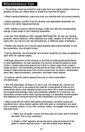
... applications, for best operation the receiver should be at least 3 feet (1 meter) above the ground and 3 feet (1 meter) away from two or more transmitters simultaneously. • Turn the transmitter off in use "general purpose" carbon batteries. If you hear scratchy noises, we suggest these steps to maintain the programmed settings. Also, since batteries installed for a long time can sometimes...
... applications, for best operation the receiver should be at least 3 feet (1 meter) above the ground and 3 feet (1 meter) away from two or more transmitters simultaneously. • Turn the transmitter off in use "general purpose" carbon batteries. If you hear scratchy noises, we suggest these steps to maintain the programmed settings. Also, since batteries installed for a long time can sometimes...

Manual
Page 15
... no audio If you must not flicker or light up . Note: This requirement is not protected from interference from any interference is received by a government or non-government operation and wireless microphone use of wireless microphone systems, and these rules are subject to change the receiver DIP Switches (4) setting to a different channel. According to operate this indicates good signal strength in operation. Cautions and Troubleshooting Low or no protection...
... no audio If you must not flicker or light up . Note: This requirement is not protected from interference from any interference is received by a government or non-government operation and wireless microphone use of wireless microphone systems, and these rules are subject to change the receiver DIP Switches (4) setting to a different channel. According to operate this indicates good signal strength in operation. Cautions and Troubleshooting Low or no protection...
Manual
Page 16
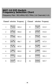
MGT-16 DIP-Switch Frequency Selection Chart Frequency Plan: 902.4MHz-923.7MHz (16 Channels) U.S. 16
MGT-16 DIP-Switch Frequency Selection Chart Frequency Plan: 902.4MHz-923.7MHz (16 Channels) U.S. 16

Manual
Page 17
Specifications MGT-16 System Frequency Response Dynamic Range Oscillating System Total Harmonic Distortion (THD) RF Carrier Frequency Range Modulation Operating Range 50Hz-16kHz (-3dB) 120dB Phase Lock Loop (PLL)
Specifications MGT-16 System Frequency Response Dynamic Range Oscillating System Total Harmonic Distortion (THD) RF Carrier Frequency Range Modulation Operating Range 50Hz-16kHz (-3dB) 120dB Phase Lock Loop (PLL)

Manual
Page 18
...past the One Year Warranty, The Nady Service Department will not repair nor be held responsible for service or replacement. If unit is clearly marked on the package. assumes the responsibility of the package. Nady Systems, Inc. Make sure the RA number is within the One Year Warranty ... factory service is enclosed (if not prepaid with credit card) with the shipment to Nady. Please make sure a cashier's check or money order is required, please call our Service Department at 510/652-2411 or e-mail service@nady.com for further instruction before sending in unit. For service,...
...past the One Year Warranty, The Nady Service Department will not repair nor be held responsible for service or replacement. If unit is clearly marked on the package. assumes the responsibility of the package. Nady Systems, Inc. Make sure the RA number is within the One Year Warranty ... factory service is enclosed (if not prepaid with credit card) with the shipment to Nady. Please make sure a cashier's check or money order is required, please call our Service Department at 510/652-2411 or e-mail service@nady.com for further instruction before sending in unit. For service,...

Manual
Page 19
... assume for repairs or replacement. This warranty gives you specific legal rights, and you may also have other liability in connection with the sale or use of sale) or we cannot be responsible for us any applicable express or implied warranties are hereby limited to state. ONE YEAR WARRANTY Nady Systems, Inc. See Service section for repair. for further instructions. This...
... assume for repairs or replacement. This warranty gives you specific legal rights, and you may also have other liability in connection with the sale or use of sale) or we cannot be responsible for us any applicable express or implied warranties are hereby limited to state. ONE YEAR WARRANTY Nady Systems, Inc. See Service section for repair. for further instructions. This...


