Installation Guide
Page 5
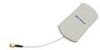
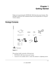
This Installation Guide provides installation instructions and guidelines for purchasing the NETGEAR 9 dBi Omni-directional Antenna. Package Contents Lightning arrestor Reverse N/SMA adapter Figure 1-1 The package should contain the following items: • NETGEAR 9 dBi Omni-directional Antenna • 2-meter low loss antenna cable to connect the antenna to a lightning arrestor 1-1 v1.0, April 2008 Chapter 1 Getting Started Thank you for using the wireless antenna.
This Installation Guide provides installation instructions and guidelines for purchasing the NETGEAR 9 dBi Omni-directional Antenna. Package Contents Lightning arrestor Reverse N/SMA adapter Figure 1-1 The package should contain the following items: • NETGEAR 9 dBi Omni-directional Antenna • 2-meter low loss antenna cable to connect the antenna to a lightning arrestor 1-1 v1.0, April 2008 Chapter 1 Getting Started Thank you for using the wireless antenna.

Installation Guide
Page 6
..., 04, or 05 cable. Please check the NETGEAR website at http://www.NETGEAR.com/go /antennas_fcc for site survey and installation assistance. Keep the carton, including the original packing materials, in extending wireless range with EU emissions and health standards and regulations. Installation Guide for the 9 dBi Omni-directional Antenna ANT2409 • Lightning Arrestor Note: A ground...
..., 04, or 05 cable. Please check the NETGEAR website at http://www.NETGEAR.com/go /antennas_fcc for site survey and installation assistance. Keep the carton, including the original packing materials, in extending wireless range with EU emissions and health standards and regulations. Installation Guide for the 9 dBi Omni-directional Antenna ANT2409 • Lightning Arrestor Note: A ground...
Installation Guide
Page 7
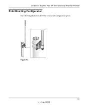
Figure 1-2 1-3 v1.0, April 2008 R Installation Guide for the 9 dBi Omni-directional Antenna ANT2409 Pole Mounting Configuration The following illustration shows the pole mount configuration option.
Figure 1-2 1-3 v1.0, April 2008 R Installation Guide for the 9 dBi Omni-directional Antenna ANT2409 Pole Mounting Configuration The following illustration shows the pole mount configuration option.
Installation Guide
Page 8
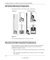
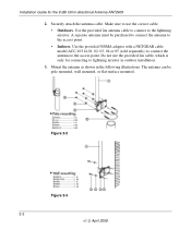
... Either right side up or up-side-down is not used. Wall Mount Figure 1-3 For wall mount installation, the L-bracket is OK. • Place the antenna in a vertical position. R R Installation Guide for the 9 dBi Omni-directional Antenna ANT2409 Flat Surface Mounting Configuration This illustration shows a flat surface mount configuration.
... Either right side up or up-side-down is not used. Wall Mount Figure 1-3 For wall mount installation, the L-bracket is OK. • Place the antenna in a vertical position. R R Installation Guide for the 9 dBi Omni-directional Antenna ANT2409 Flat Surface Mounting Configuration This illustration shows a flat surface mount configuration.
Installation Guide
Page 9
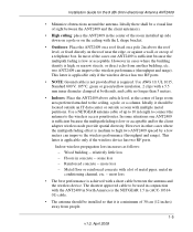
... wireless device. Installation Guide for the 9 dBi Omni-directional Antenna ANT2409 • Minimize obstructions around the antenna. However in concrete -- Use AWG 10, UL 1015, Standard 600 V, 105°C, green or green/yellow insulation, 2 clips with the ANT2409 in North America is the NETGEAR 1.5 m (ACC-1031401) cable. • The antenna should be used in conjunction with a 5.5 mm...
... wireless device. Installation Guide for the 9 dBi Omni-directional Antenna ANT2409 • Minimize obstructions around the antenna. However in concrete -- Use AWG 10, UL 1015, Standard 600 V, 105°C, green or green/yellow insulation, 2 clips with the ANT2409 in North America is the NETGEAR 1.5 m (ACC-1031401) cable. • The antenna should be used in conjunction with a 5.5 mm...
Installation Guide
Page 10
Installation Guide for the 9 dBi Omni-directional Antenna ANT2409 1-6 v1.0, April 2008
Installation Guide for the 9 dBi Omni-directional Antenna ANT2409 1-6 v1.0, April 2008
Installation Guide
Page 12
... cable. • Outdoors. Securely attach the antenna cable. A seperate antenna must be pole mounted, wall mounted, or flat-surface mounted. The antenna can be purchased to connect the antenna to use the provided 2m cable, which is only for the 9 dBi Omni-directional Antenna ANT2409 2. Use the provided N/SMA adapter with a NETGEAR cable model ACC-10314-01, 02, 03...
... cable. • Outdoors. Securely attach the antenna cable. A seperate antenna must be pole mounted, wall mounted, or flat-surface mounted. The antenna can be purchased to connect the antenna to use the provided 2m cable, which is only for the 9 dBi Omni-directional Antenna ANT2409 2. Use the provided N/SMA adapter with a NETGEAR cable model ACC-10314-01, 02, 03...

Installation Guide
Page 13
Installation Guide for the 9 dBi Omni-directional Antenna ANT2409 Figure 2-4 2-3 v1.0, April 2008
Installation Guide for the 9 dBi Omni-directional Antenna ANT2409 Figure 2-4 2-3 v1.0, April 2008
Installation Guide
Page 14
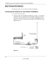
... the lightning arrestor. Connect the other side of the cable to either of the two RF ports on page 1-3, the antenna should have been assembled for the 9 dBi Omni-directional Antenna ANT2409 Now, Connect the Antenna The instructions below cover outdoor and indoor installations. Installation Guide for outdoor installation using the provided 2meter cable. Connecting the...
... the lightning arrestor. Connect the other side of the cable to either of the two RF ports on page 1-3, the antenna should have been assembled for the 9 dBi Omni-directional Antenna ANT2409 Now, Connect the Antenna The instructions below cover outdoor and indoor installations. Installation Guide for outdoor installation using the provided 2meter cable. Connecting the...
Installation Guide
Page 15
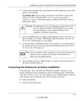
... must be used for indoor installation using a NETGEAR cable ACC-10314-01, 02, 03, 04 or 05 and the reverse N/SMA adaptor connected to the network and turn them on page 2-1, the antenna should not have been assembled for outdoor installation. Connecting the Antenna for the 9 dBi Omni-directional Antenna ANT2409 1. Note: On access points with these...
... must be used for indoor installation using a NETGEAR cable ACC-10314-01, 02, 03, 04 or 05 and the reverse N/SMA adaptor connected to the network and turn them on page 2-1, the antenna should not have been assembled for outdoor installation. Connecting the Antenna for the 9 dBi Omni-directional Antenna ANT2409 1. Note: On access points with these...
Installation Guide
Page 16
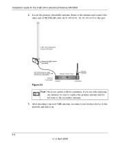
Remove the antenna and connect the other end of NETGEAR cable ACC-10314-01, 02, 03, 04 or 05 to this port. (provided) Figure 2-6 Note: On access points with two antennas, if you are only replacing one antenna, be sure to the network and turn it on. 2-6 v1.0, April 2008 Installation Guide for the 9 dBi Omni-directional Antenna ANT2409 2. After attaching your new 9dBi antenna, reconnect your wireless device to replace the primary antenna and do not remove the secondary antenna. 3. Locate the primary detachable antenna.
Remove the antenna and connect the other end of NETGEAR cable ACC-10314-01, 02, 03, 04 or 05 to this port. (provided) Figure 2-6 Note: On access points with two antennas, if you are only replacing one antenna, be sure to the network and turn it on. 2-6 v1.0, April 2008 Installation Guide for the 9 dBi Omni-directional Antenna ANT2409 2. After attaching your new 9dBi antenna, reconnect your wireless device to replace the primary antenna and do not remove the secondary antenna. 3. Locate the primary detachable antenna.
Installation Guide
Page 18
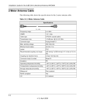
...Yes UV resistant 3-2 v1.0, April 2008 Installation Guide for the 9 dBi Omni-directional Antenna ANT2409 2 Meter Antenna Cable The following table shows the specifications for the 2 meter antenna cable. working voltage Minimum bend radius Jacket Recommended coupling nut torque ... Operating temperature/humidity Transportation temperature/humidity Storage temperature/humidity Waterproof RoHS compliant UV 0-3 GHz 1.5: 1 max. Table 3-2. 2 Meter Antenna Cable Specifications Frequency range VSWR Cable type Transmission loss Connector type Max. CFD200 (coaxial cable) 1.5 dB max. @ 2.4-2.5 GHz...
...Yes UV resistant 3-2 v1.0, April 2008 Installation Guide for the 9 dBi Omni-directional Antenna ANT2409 2 Meter Antenna Cable The following table shows the specifications for the 2 meter antenna cable. working voltage Minimum bend radius Jacket Recommended coupling nut torque ... Operating temperature/humidity Transportation temperature/humidity Storage temperature/humidity Waterproof RoHS compliant UV 0-3 GHz 1.5: 1 max. Table 3-2. 2 Meter Antenna Cable Specifications Frequency range VSWR Cable type Transmission loss Connector type Max. CFD200 (coaxial cable) 1.5 dB max. @ 2.4-2.5 GHz...

Installation Guide
Page 19
... PTFE Silicone Rubber -30°C to +80°C (-22 oF to 176 oF) Rain resistant RoHS compliant Yes 3-3 v1.0, April 2008 Installation Guide for the 9 dBi Omni-directional Antenna ANT2409 N/SMA Adaptor Accessory The following table shows the specifications for the N/SMA adapter accessory. Table 3-3. 2 N/SMA Adapter Accessory Illustration Specifications Frequency range 0-3 GHz VSWR...
... PTFE Silicone Rubber -30°C to +80°C (-22 oF to 176 oF) Rain resistant RoHS compliant Yes 3-3 v1.0, April 2008 Installation Guide for the 9 dBi Omni-directional Antenna ANT2409 N/SMA Adaptor Accessory The following table shows the specifications for the N/SMA adapter accessory. Table 3-3. 2 N/SMA Adapter Accessory Illustration Specifications Frequency range 0-3 GHz VSWR...

Installation Guide
Page 20
Table 3-4. Installation Guide for the 9 dBi Omni-directional Antenna ANT2409 Lightning Arrestor Specifications The following table lists the specifications for the lightning arrestor. withstanding current 5000 A, 8/20 μ Overvoltage protection 90V min. (100mA, < 150ms) ...
Table 3-4. Installation Guide for the 9 dBi Omni-directional Antenna ANT2409 Lightning Arrestor Specifications The following table lists the specifications for the lightning arrestor. withstanding current 5000 A, 8/20 μ Overvoltage protection 90V min. (100mA, < 150ms) ...
Installation Guide
Page 21
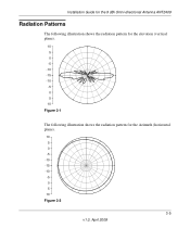
Installation Guide for the 9 dBi Omni-directional Antenna ANT2409 Radiation Patterns The following illustration shows the radiation pattern for the elevation (vertical plane). 10 5 0 -5 -10 -15 -10 -5 0 5 10 Figure 3-1 The following illustration shows the radiation pattern for the Azimuth (horizontal plane). 10 5 0 -5 -10 -15 -10 -5 0 5 10 Figure 3-2 3-5 v1.0, April 2008
Installation Guide for the 9 dBi Omni-directional Antenna ANT2409 Radiation Patterns The following illustration shows the radiation pattern for the elevation (vertical plane). 10 5 0 -5 -10 -15 -10 -5 0 5 10 Figure 3-1 The following illustration shows the radiation pattern for the Azimuth (horizontal plane). 10 5 0 -5 -10 -15 -10 -5 0 5 10 Figure 3-2 3-5 v1.0, April 2008

Installation Guide
Page 22
Installation Guide for the 9 dBi Omni-directional Antenna ANT2409 3-6 v1.0, April 2008
Installation Guide for the 9 dBi Omni-directional Antenna ANT2409 3-6 v1.0, April 2008
