Installation Guide
Page 2
.../go /antannas_eu for use with the maximum level authorized by NETGEAR, Inc. Microsoft, Windows, and Windows NT are trademarks or registered trademarks of NETGEAR, Inc. Federal Communications Commission (FCC) Compliance Notice: Radio Frequency Notice In the U.S., the ANT2409 antenna should only be used with devices that have been FCC approved for product combinations that...
.../go /antannas_eu for use with the maximum level authorized by NETGEAR, Inc. Microsoft, Windows, and Windows NT are trademarks or registered trademarks of NETGEAR, Inc. Federal Communications Commission (FCC) Compliance Notice: Radio Frequency Notice In the U.S., the ANT2409 antenna should only be used with devices that have been FCC approved for product combinations that...

Installation Guide
Page 6
...plastic anchors • This Installation Guide, and a Warranty and Support Information card If any antenna requires careful planning and extra consideration to return the product for use a NETGEAR model ACC-10314-01, 02, 03, 04, or 05 cable. The grounding cable .... Antenna cable for site survey and installation assistance. Please check the NETGEAR website at http://www.NETGEAR.com/go /antennas_fcc for outdoor installation. Antenna installation must be used with devices that have been FCC approved for repair. Installation Guide for the 9 dBi Omni-directional Antenna ANT2409 &#...
...plastic anchors • This Installation Guide, and a Warranty and Support Information card If any antenna requires careful planning and extra consideration to return the product for use a NETGEAR model ACC-10314-01, 02, 03, 04, or 05 cable. The grounding cable .... Antenna cable for site survey and installation assistance. Please check the NETGEAR website at http://www.NETGEAR.com/go /antennas_fcc for outdoor installation. Antenna installation must be used with devices that have been FCC approved for repair. Installation Guide for the 9 dBi Omni-directional Antenna ANT2409 &#...
Installation Guide
Page 7
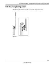
R Installation Guide for the 9 dBi Omni-directional Antenna ANT2409 Pole Mounting Configuration The following illustration shows the pole mount configuration option. Figure 1-2 1-3 v1.0, April 2008
R Installation Guide for the 9 dBi Omni-directional Antenna ANT2409 Pole Mounting Configuration The following illustration shows the pole mount configuration option. Figure 1-2 1-3 v1.0, April 2008
Installation Guide
Page 8
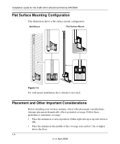
... potential coverage. Wall Mount Figure 1-3 For wall mount installation, the L-bracket is OK. • Place the antenna in a vertical position. Either right side up or up-side-down is not used. R R Installation Guide for the 9 dBi Omni-directional Antenna ANT2409 Flat Surface Mounting Configuration This illustration shows a flat surface mount configuration. Placement and Other Important Considerations...
... potential coverage. Wall Mount Figure 1-3 For wall mount installation, the L-bracket is OK. • Place the antenna in a vertical position. Either right side up or up-side-down is not used. R R Installation Guide for the 9 dBi Omni-directional Antenna ANT2409 Flat Surface Mounting Configuration This illustration shows a flat surface mount configuration. Placement and Other Important Considerations...
Installation Guide
Page 9
... 30 cm (12 inches) away from another building, etc. most of a telephone box. Installation Guide for the 9 dBi Omni-directional Antenna ANT2409 • Minimize obstructions around the antenna. This latter is applicable only if the wireless device has two RF ports. • NOTE: Ground cable is not...in North America is the NETGEAR 1.5 m (ACC-1031401) cable. • The antenna should be a visual line of up side down on a pole or on the ceiling with a short cable between the ANT2409 and the client antenna(s). • High ceiling: place the ANT2409 in other cases where the...
... 30 cm (12 inches) away from another building, etc. most of a telephone box. Installation Guide for the 9 dBi Omni-directional Antenna ANT2409 • Minimize obstructions around the antenna. This latter is applicable only if the wireless device has two RF ports. • NOTE: Ground cable is not...in North America is the NETGEAR 1.5 m (ACC-1031401) cable. • The antenna should be a visual line of up side down on a pole or on the ceiling with a short cable between the ANT2409 and the client antenna(s). • High ceiling: place the ANT2409 in other cases where the...
Installation Guide
Page 10
Installation Guide for the 9 dBi Omni-directional Antenna ANT2409 1-6 v1.0, April 2008
Installation Guide for the 9 dBi Omni-directional Antenna ANT2409 1-6 v1.0, April 2008
Installation Guide
Page 12
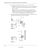
... a NETGEAR cable model ACC-10314-01, 02, 03, 04 or 05 (sold separately) to connect the antenna to the access point. • Indoors. Mount the antenna as shown in outdoor installation. 3. Make sure to lightning arrestor in the following illustrations. Do not use the provided 2m cable, which is only for the 9 dBi Omni-directional Antenna ANT2409 2. Installation...
... a NETGEAR cable model ACC-10314-01, 02, 03, 04 or 05 (sold separately) to connect the antenna to the access point. • Indoors. Mount the antenna as shown in outdoor installation. 3. Make sure to lightning arrestor in the following illustrations. Do not use the provided 2m cable, which is only for the 9 dBi Omni-directional Antenna ANT2409 2. Installation...

Installation Guide
Page 13
Installation Guide for the 9 dBi Omni-directional Antenna ANT2409 Figure 2-4 2-3 v1.0, April 2008
Installation Guide for the 9 dBi Omni-directional Antenna ANT2409 Figure 2-4 2-3 v1.0, April 2008
Installation Guide
Page 14
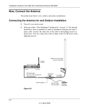
..." on the lightning arrestor. Connect the other side of the cable to either of the two RF ports on page 1-3, the antenna should have been assembled for the 9 dBi Omni-directional Antenna ANT2409 Now, Connect the Antenna The instructions below cover outdoor and indoor installations. Figure 2-5 2-4 v1.0, April 2008 Turn off your wireless unit. 2. You can connect...
..." on the lightning arrestor. Connect the other side of the cable to either of the two RF ports on page 1-3, the antenna should have been assembled for the 9 dBi Omni-directional Antenna ANT2409 Now, Connect the Antenna The instructions below cover outdoor and indoor installations. Figure 2-5 2-4 v1.0, April 2008 Turn off your wireless unit. 2. You can connect...
Installation Guide
Page 15
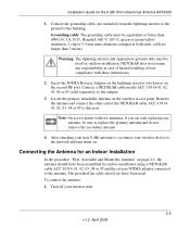
... arrestor (clockwise) on the wireless access point. Remove the antenna and connect the other end of noncompliance with two antennas, if you are only replacing one antenna, be equivalent or better than 5 meters. The provided 2m cable should have been used for the 9 dBi Omni-directional Antenna ANT2409 1. Connect a NETGEAR cable model ACC-10314-01, 02, 03, 04 or...
... arrestor (clockwise) on the wireless access point. Remove the antenna and connect the other end of noncompliance with two antennas, if you are only replacing one antenna, be equivalent or better than 5 meters. The provided 2m cable should have been used for the 9 dBi Omni-directional Antenna ANT2409 1. Connect a NETGEAR cable model ACC-10314-01, 02, 03, 04 or...
Installation Guide
Page 16
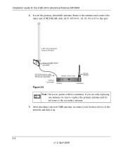
Remove the antenna and connect the other end of NETGEAR cable ACC-10314-01, 02, 03, 04 or 05 to this port. (provided) Figure 2-6 Note: On access points with two antennas, if you are only replacing one antenna, be sure to the network and turn it on. 2-6 v1.0, April 2008 Locate the primary detachable antenna. After attaching your new 9dBi antenna, reconnect your wireless device to replace the primary antenna and do not remove the secondary antenna. 3. Installation Guide for the 9 dBi Omni-directional Antenna ANT2409 2.
Remove the antenna and connect the other end of NETGEAR cable ACC-10314-01, 02, 03, 04 or 05 to this port. (provided) Figure 2-6 Note: On access points with two antennas, if you are only replacing one antenna, be sure to the network and turn it on. 2-6 v1.0, April 2008 Locate the primary detachable antenna. After attaching your new 9dBi antenna, reconnect your wireless device to replace the primary antenna and do not remove the secondary antenna. 3. Installation Guide for the 9 dBi Omni-directional Antenna ANT2409 2.
Installation Guide
Page 18
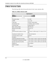
Table 3-2. 2 Meter Antenna Cable Specifications Frequency range VSWR Cable type Transmission loss Connector type Max. CFD200 (coaxial cable) 1.5 dB max. @ 2.4-2.5 GHz N plug female* 2 250 Vrms min. 25 mm...176;C (-40°F to 185°F)/ 20 to 10.0 in lbs) 2.5 kg* (5.5 lbs) min. Installation Guide for the 9 dBi Omni-directional Antenna ANT2409 2 Meter Antenna Cable The following table shows the specifications for the 2 meter antenna cable. working voltage Minimum bend radius Jacket Recommended coupling nut torque Coupling nut retention force Connector body & contact Insulation Operating...
Table 3-2. 2 Meter Antenna Cable Specifications Frequency range VSWR Cable type Transmission loss Connector type Max. CFD200 (coaxial cable) 1.5 dB max. @ 2.4-2.5 GHz N plug female* 2 250 Vrms min. 25 mm...176;C (-40°F to 185°F)/ 20 to 10.0 in lbs) 2.5 kg* (5.5 lbs) min. Installation Guide for the 9 dBi Omni-directional Antenna ANT2409 2 Meter Antenna Cable The following table shows the specifications for the 2 meter antenna cable. working voltage Minimum bend radius Jacket Recommended coupling nut torque Coupling nut retention force Connector body & contact Insulation Operating...

Installation Guide
Page 19
Installation Guide for the 9 dBi Omni-directional Antenna ANT2409 N/SMA Adaptor Accessory The following table shows the specifications for the N/SMA adapter accessory. Table 3-3. 2 N/SMA Adapter Accessory Illustration Specifications Frequency range 0-3 GHz VSWR Connector ...
Installation Guide for the 9 dBi Omni-directional Antenna ANT2409 N/SMA Adaptor Accessory The following table shows the specifications for the N/SMA adapter accessory. Table 3-3. 2 N/SMA Adapter Accessory Illustration Specifications Frequency range 0-3 GHz VSWR Connector ...

Installation Guide
Page 20
Installation Guide for the 9 dBi Omni-directional Antenna ANT2409 Lightning Arrestor Specifications The following table lists the specifications for the lightning arrestor. Table 3-4. Lightning Arrestor Illustration Specifications Frequency range 0-6 GHz VSWR Insertion loss Impulse ...
Installation Guide for the 9 dBi Omni-directional Antenna ANT2409 Lightning Arrestor Specifications The following table lists the specifications for the lightning arrestor. Table 3-4. Lightning Arrestor Illustration Specifications Frequency range 0-6 GHz VSWR Insertion loss Impulse ...
Installation Guide
Page 21
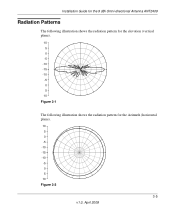
Installation Guide for the 9 dBi Omni-directional Antenna ANT2409 Radiation Patterns The following illustration shows the radiation pattern for the elevation (vertical plane). 10 5 0 -5 -10 -15 -10 -5 0 5 10 Figure 3-1 The following illustration shows the radiation pattern for the Azimuth (horizontal plane). 10 5 0 -5 -10 -15 -10 -5 0 5 10 Figure 3-2 3-5 v1.0, April 2008
Installation Guide for the 9 dBi Omni-directional Antenna ANT2409 Radiation Patterns The following illustration shows the radiation pattern for the elevation (vertical plane). 10 5 0 -5 -10 -15 -10 -5 0 5 10 Figure 3-1 The following illustration shows the radiation pattern for the Azimuth (horizontal plane). 10 5 0 -5 -10 -15 -10 -5 0 5 10 Figure 3-2 3-5 v1.0, April 2008

Installation Guide
Page 22
Installation Guide for the 9 dBi Omni-directional Antenna ANT2409 3-6 v1.0, April 2008
Installation Guide for the 9 dBi Omni-directional Antenna ANT2409 3-6 v1.0, April 2008