
Installation Guide
Page 5
... Switching Technology 1-1 Types of Ethernet Switches 1-2 Model FS509 Switch Overview 1-3 Features ...1-4 Chapter 2 Physical Description Front Panel ...2-1 1000BASE-SX Fiber Ports 2-3 Normal/Uplink Push Button 2-3 LEDs ...2-4 Rear Panel ...2-6 FDX/AUTO Duplex 10/100 Toggle Switches 2-6 FDX/Auto Gigabit Toggle Switch 2-7 Chapter 3 Applications Desktop Switching ...3-2 Segment Switching ...3-3 Chapter 4 Installation Preparing the Site ...4-1 Checking Package Contents 4-1 Installing a Switch ...4-2 Installing the Switch on a Flat Surface 4-2 Installing the Switch in a Rack 4-3 Connecting...
... Switching Technology 1-1 Types of Ethernet Switches 1-2 Model FS509 Switch Overview 1-3 Features ...1-4 Chapter 2 Physical Description Front Panel ...2-1 1000BASE-SX Fiber Ports 2-3 Normal/Uplink Push Button 2-3 LEDs ...2-4 Rear Panel ...2-6 FDX/AUTO Duplex 10/100 Toggle Switches 2-6 FDX/Auto Gigabit Toggle Switch 2-7 Chapter 3 Applications Desktop Switching ...3-2 Segment Switching ...3-3 Chapter 4 Installation Preparing the Site ...4-1 Checking Package Contents 4-1 Installing a Switch ...4-2 Installing the Switch on a Flat Surface 4-2 Installing the Switch in a Rack 4-3 Connecting...
Installation Guide
Page 11
... backbone bottlenecks, the Model FS509 switch also has a Gigabit Ethernet uplink port. With this information, switches forward cross-segment traffic only to each of the 10 users is located on which equals 1 Mbps of 10 users, the average bandwidth available to each user on a 10 Mbps network is designed to support power workgroups operating at either 10 megabits per user. Ethernet switches significantly increase network throughput by segmenting network traffic. Chapter 1 Introduction...
... backbone bottlenecks, the Model FS509 switch also has a Gigabit Ethernet uplink port. With this information, switches forward cross-segment traffic only to each of the 10 users is located on which equals 1 Mbps of 10 users, the average bandwidth available to each user on a 10 Mbps network is designed to support power workgroups operating at either 10 megabits per user. Ethernet switches significantly increase network throughput by segmenting network traffic. Chapter 1 Introduction...
Installation Guide
Page 12
... each port having significant memory buffering and supporting thousands of Ethernet Switches Ethernet switches can also be classified in throughput. Gigabit (1000) Mbps switches are obtained very quickly and at 100 Mbps and sending traffic to the server, the server needs a faster transmission speed to the desktop (the network interface cards or software and the network wiring). As a result, the performance upgrade and the applications it enables are used when...
... each port having significant memory buffering and supporting thousands of Ethernet Switches Ethernet switches can also be classified in throughput. Gigabit (1000) Mbps switches are obtained very quickly and at 100 Mbps and sending traffic to the server, the server needs a faster transmission speed to the desktop (the network interface cards or software and the network wiring). As a result, the performance upgrade and the applications it enables are used when...

Installation Guide
Page 13
... used to connect to support advanced applications. With one Model FS509 switch, the reach extends to function as a single logical network. This full-duplex 1000BASE-SX port allows users to extend the reach of the device. Because the Model FS509 switch is an ISO media access control (MAC) layer device, the switch is network protocol independent and compatible with a Gigabit uplink interface. The Gigabit Ethernet uplink port on the Model FS509 switch can adapt automatically to 550 meters away. By installing a Model FS509 switch, a user...
... used to connect to support advanced applications. With one Model FS509 switch, the reach extends to function as a single logical network. This full-duplex 1000BASE-SX port allows users to extend the reach of the device. Because the Model FS509 switch is an ISO media access control (MAC) layer device, the switch is network protocol independent and compatible with a Gigabit uplink interface. The Gigabit Ethernet uplink port on the Model FS509 switch can adapt automatically to 550 meters away. By installing a Model FS509 switch, a user...
Installation Guide
Page 14
The duplex toggle switch can be set to full-duplex if the connected port is operating at full-duplex mode. • One full-duplex Gigabit fiber port with a standard SC connector The port supports multimode optical fiber (SX) up to 8,000 MAC addresses (that is, the switch can be connected to a hub using simple Category 5 unshielded twisted pair (UTP) cable • Eight vista RJ-45 network ports with built-in LEDs to monitor individual port status • Switch-selectable autonegotiating...
The duplex toggle switch can be set to full-duplex if the connected port is operating at full-duplex mode. • One full-duplex Gigabit fiber port with a standard SC connector The port supports multimode optical fiber (SX) up to 8,000 MAC addresses (that is, the switch can be connected to a hub using simple Category 5 unshielded twisted pair (UTP) cable • Eight vista RJ-45 network ports with built-in LEDs to monitor individual port status • Switch-selectable autonegotiating...

Installation Guide
Page 15
IEEE 802.3z 1000BASE-SX standard • Rack Mount Kit provided for installing the switch in a standard 19-inch equipment rack or for mounting on the wall • A 62.5/125 µm fiber cable included for the Model FS509 Fast Ethernet Switch • Conformity to a server or the network backbone Introduction 1-5 IEEE 802.3u and 802.3z 100BASE-TX standard - ISO/IEC 8802-3 and ANSI/IEEE 802.3 10BASE-T standards - Installation Guide for connecting the Gigabit port to standards: -
IEEE 802.3z 1000BASE-SX standard • Rack Mount Kit provided for installing the switch in a standard 19-inch equipment rack or for mounting on the wall • A 62.5/125 µm fiber cable included for the Model FS509 Fast Ethernet Switch • Conformity to a server or the network backbone Introduction 1-5 IEEE 802.3u and 802.3z 100BASE-TX standard - ISO/IEC 8802-3 and ANSI/IEEE 802.3 10BASE-T standards - Installation Guide for connecting the Gigabit port to standards: -

Installation Guide
Page 17
... easier management and control of the Model FS509 switch, familiarize yourself with the ports, LEDs, and Normal/Uplink push button on each port 5 = Normal/Uplink push button for port 8 6 = Gigabit Ethernet (1000BASE-SX) SC fiber port 7 = Link LED for the Gigabit Ethernet port Figure 2-1. Chapter 2 Physical Description This chapter describes the hardware features of the NETGEAR Model FS509 Fast Ethernet Switch with 10M or 100M Link LEDs on the front panel of the switch, as illustrated in Figure 2-1. 1 2 5 7 9PORT Fast 10/100Mbps Ethernet Switch Power Rx...
... easier management and control of the Model FS509 switch, familiarize yourself with the ports, LEDs, and Normal/Uplink push button on each port 5 = Normal/Uplink push button for port 8 6 = Gigabit Ethernet (1000BASE-SX) SC fiber port 7 = Link LED for the Gigabit Ethernet port Figure 2-1. Chapter 2 Physical Description This chapter describes the hardware features of the NETGEAR Model FS509 Fast Ethernet Switch with 10M or 100M Link LEDs on the front panel of the switch, as illustrated in Figure 2-1. 1 2 5 7 9PORT Fast 10/100Mbps Ethernet Switch Power Rx...

Installation Guide
Page 18
... RJ-45 connector and the RJ-45 plug, refer to the port is valid and that have built-in LEDs, as described in Figure 2-2. The 10/100 Mbps ports support only unshielded twisted pair (UTP) cable using an 8-pin RJ-45 plug. The network access speed for the Model FS509 Fast Ethernet Switch As Figure 2-1 shows, the Model FS509 switch is operating at either 10 or 100 Mbps.
... RJ-45 connector and the RJ-45 plug, refer to the port is valid and that have built-in LEDs, as described in Figure 2-2. The 10/100 Mbps ports support only unshielded twisted pair (UTP) cable using an 8-pin RJ-45 plug. The network access speed for the Model FS509 Fast Ethernet Switch As Figure 2-1 shows, the Model FS509 switch is operating at either 10 or 100 Mbps.

Installation Guide
Page 19
... push button is configured for port 8 on the front panel of the 1000BASE-SX fiber port indicates whether or not proper signaling is established with the remote port. Never look into an optical fiber or connector port. Figure 2-3 shows a fiber optic cable connection to a light source. This port operates at 1000 Mbps full-duplex exclusively and provides a standard duplex SC connector for the Model FS509 Fast Ethernet Switch 1000BASE-SX Fiber Ports The Model FS509 switch...
... push button is configured for port 8 on the front panel of the 1000BASE-SX fiber port indicates whether or not proper signaling is established with the remote port. Never look into an optical fiber or connector port. Figure 2-3 shows a fiber optic cable connection to a light source. This port operates at 1000 Mbps full-duplex exclusively and provides a standard duplex SC connector for the Model FS509 Fast Ethernet Switch 1000BASE-SX Fiber Ports The Model FS509 switch...

Installation Guide
Page 21
... of the fiber connector) Activity On Off Blinking Off On On Off On Off Description Power is supplied to the switch. On A valid 1000 Mbps link is occurring on the port when operating in half-duplex mode. The blinking action corresponds to the right of the Model FS509 switch. No packet transmission or reception is established on the port. Table 2-1. Off No 10 Mbps link is established...
... of the fiber connector) Activity On Off Blinking Off On On Off On Off Description Power is supplied to the switch. On A valid 1000 Mbps link is occurring on the port when operating in half-duplex mode. The blinking action corresponds to the right of the Model FS509 switch. No packet transmission or reception is established on the port. Table 2-1. Off No 10 Mbps link is established...

Installation Guide
Page 22
.../AUTO toggle switch (for port 9) 3 = Cooling fan 4 = AC power outlet Figure 2-4. If the remote port cannot provide the proper signal to indicate its own capability, the 10/100 Mbps port on the switch should be set the duplex mode to operate at full duplex AUTO- Setting the toggle switch to AUTO on the operating mode of devices. FDX- Installation Guide for the Model FS509 Fast Ethernet Switch Rear Panel As illustrated in either full- If supported...
.../AUTO toggle switch (for port 9) 3 = Cooling fan 4 = AC power outlet Figure 2-4. If the remote port cannot provide the proper signal to indicate its own capability, the 10/100 Mbps port on the switch should be set the duplex mode to operate at full duplex AUTO- Setting the toggle switch to AUTO on the operating mode of devices. FDX- Installation Guide for the Model FS509 Fast Ethernet Switch Rear Panel As illustrated in either full- If supported...
Installation Guide
Page 23
...-duplex mode; Note: NETGEAR recommends that all Fast Ethernet topology rules are assigned to each 10/100 Mbps port on the Model FS509 switch. The communication mode can be connected to either full-duplex or auto-duplex mode. Installation Guide for the Model FS509 Fast Ethernet Switch As Figure 2-4 shows, a full-duplex (FDX) toggle switch or an auto-duplex (AUTO) toggle switch are followed. Physical Description 2-7 setting the switch to FDX mode does not enable the port to advertise that it is the factory setting...
...-duplex mode; Note: NETGEAR recommends that all Fast Ethernet topology rules are assigned to each 10/100 Mbps port on the Model FS509 switch. The communication mode can be connected to either full-duplex or auto-duplex mode. Installation Guide for the Model FS509 Fast Ethernet Switch As Figure 2-4 shows, a full-duplex (FDX) toggle switch or an auto-duplex (AUTO) toggle switch are followed. Physical Description 2-7 setting the switch to FDX mode does not enable the port to advertise that it is the factory setting...
Installation Guide
Page 25
... can be used with multiple users or workgroups and other interconnection devices in various configurations. The configuration examples in this chapter illustrate the integration of the NETGEAR Model FS509 Gigabit Ethernet Switch in configuring your network. Applications 3-1 The Model FS509 switch is designed to provide flexibility in network environments of a few workstations connected to a printer or a segmented network with 10 Mbps, 100 Mbps, or 1000 Mbps hubs or other networking devices. Chapter...
... can be used with multiple users or workgroups and other interconnection devices in various configurations. The configuration examples in this chapter illustrate the integration of the NETGEAR Model FS509 Gigabit Ethernet Switch in configuring your network. Applications 3-1 The Model FS509 switch is designed to provide flexibility in network environments of a few workstations connected to a printer or a segmented network with 10 Mbps, 100 Mbps, or 1000 Mbps hubs or other networking devices. Chapter...
Installation Guide
Page 26
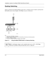
... switch used as a desktop switch to build a small network that enables users to have Gigabit (1000 Mbps) access to a file server. 1 9PORT Fast 10/100Mbps Ethernet Switch Power Rx/Tx 1 234 5 678 9 Green = FDX, Yellow = COL 100M 1 10M 2 3 4 5 6 7 8 On = Link Normal/Uplink 1 Ethernet MODEL FS509 Tx Rx 1000M Link 2 3 4 8929FA Key: 1 = Server with 1000 Mbps connection 2 = Model FS509 Fast Ethernet Switch (Normal/Uplink push button set to Normal position) 3 = PC with 10 Mbps connection 4 = PCs with 100 Mbps Fast Ethernet adapter cards installed Figure 3-1. Installation Guide...
... switch used as a desktop switch to build a small network that enables users to have Gigabit (1000 Mbps) access to a file server. 1 9PORT Fast 10/100Mbps Ethernet Switch Power Rx/Tx 1 234 5 678 9 Green = FDX, Yellow = COL 100M 1 10M 2 3 4 5 6 7 8 On = Link Normal/Uplink 1 Ethernet MODEL FS509 Tx Rx 1000M Link 2 3 4 8929FA Key: 1 = Server with 1000 Mbps connection 2 = Model FS509 Fast Ethernet Switch (Normal/Uplink push button set to Normal position) 3 = PC with 10 Mbps connection 4 = PCs with 100 Mbps Fast Ethernet adapter cards installed Figure 3-1. Installation Guide...
Installation Guide
Page 27
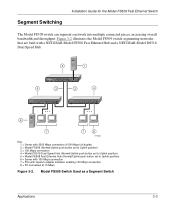
... On = Link Normal/Uplink 1 Ethernet MODEL FS509 Tx Rx 1000M Link 3 3 4 6 7 7 8 8954FA Key: 1 = Server with 2000 Mbps connection (1000 Mbps full-duplex) 2 = Model FS509 (Normal/Uplink push button set to Uplink position) 3 = 100 Mbps connection 4 = Model DS516 Dual Speed Hub (Normal/Uplink push button set to Uplink position) 5 = Model FE508 Fast Ethernet Hub (Normal/Uplink push button set to Uplink position) 6 = Server with 100 Mbps connection 7 = PCs with network adapter installed, enabling 100 Mbps connection 8 = PC connected at 10 Mbps Figure 3-2. Model FS509 Switch Used as...
... On = Link Normal/Uplink 1 Ethernet MODEL FS509 Tx Rx 1000M Link 3 3 4 6 7 7 8 8954FA Key: 1 = Server with 2000 Mbps connection (1000 Mbps full-duplex) 2 = Model FS509 (Normal/Uplink push button set to Uplink position) 3 = 100 Mbps connection 4 = Model DS516 Dual Speed Hub (Normal/Uplink push button set to Uplink position) 5 = Model FE508 Fast Ethernet Hub (Normal/Uplink push button set to Uplink position) 6 = Server with 100 Mbps connection 7 = PCs with network adapter installed, enabling 100 Mbps connection 8 = PC connected at 10 Mbps Figure 3-2. Model FS509 Switch Used as...
Installation Guide
Page 29
... the following list: • NETGEAR Model FS509 Fast Ethernet Switch • Fiber cable • Self-adhesive rubber footpads for desktop installation • Rack Mount Kit for the Model FS509 switch. Checking Package Contents Unpack the contents of the switch, as required by your national electrical codes and ordinances. Preparing the Site Before you begin installing the switch, prepare the installation site. Chapter 4 Installation This chapter describes the installation procedures for rack installation • AC power cord...
... the following list: • NETGEAR Model FS509 Fast Ethernet Switch • Fiber cable • Self-adhesive rubber footpads for desktop installation • Rack Mount Kit for the Model FS509 switch. Checking Package Contents Unpack the contents of the switch, as required by your national electrical codes and ordinances. Preparing the Site Before you begin installing the switch, prepare the installation site. Chapter 4 Installation This chapter describes the installation procedures for rack installation • AC power cord...
Installation Guide
Page 32
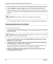
... the fiber cable to the Gigabit uplink port and the other devices, refer to "Connecting Devices to the switch: 1. Check the ON/OFF link negotiation toggle switch on the rear panel for the Model FS509 Fast Ethernet Switch 5. Connecting Devices to the Switch To connect devices to the Switch." To connect additional switches or other end to the rack. For more information, refer to 328 feet (100 meters) in Chapter 4, "Installation." 4. Installation Guide for the selected duplex mode (the default setting...
... the fiber cable to the Gigabit uplink port and the other devices, refer to "Connecting Devices to the switch: 1. Check the ON/OFF link negotiation toggle switch on the rear panel for the Model FS509 Fast Ethernet Switch 5. Connecting Devices to the Switch To connect devices to the Switch." To connect additional switches or other end to the rack. For more information, refer to 328 feet (100 meters) in Chapter 4, "Installation." 4. Installation Guide for the selected duplex mode (the default setting...

Installation Guide
Page 33
... Ethernet 2 3 4 Switch Rx/Tx Green = FDX, 5 6 Yellow = 7 COL 8 9 100M 1 10M 2 3 4 5 6 1 7 8 On = Link Normal/Uplink Ethernet Tx Rx 1000M Link MODEL FS509 2 rnet Tx Rx 100 3 and 4 1 8 FDX Duplex Mode AUTO Figure 4-2. 8953FA Connecting to Figure 4-2 when connecting the Model FS509 switch. The link negotiation state of the preceding steps has a corresponding reference number in the illustration. Installation 4-5 Installation Guide for the Model FS509 Fast Ethernet Switch 5. Each of the Gigabit Ethernet port (ON or OFF) must be the same as its remote port. Connect...
... Ethernet 2 3 4 Switch Rx/Tx Green = FDX, 5 6 Yellow = 7 COL 8 9 100M 1 10M 2 3 4 5 6 1 7 8 On = Link Normal/Uplink Ethernet Tx Rx 1000M Link MODEL FS509 2 rnet Tx Rx 100 3 and 4 1 8 FDX Duplex Mode AUTO Figure 4-2. 8953FA Connecting to Figure 4-2 when connecting the Model FS509 switch. The link negotiation state of the preceding steps has a corresponding reference number in the illustration. Installation 4-5 Installation Guide for the Model FS509 Fast Ethernet Switch 5. Each of the Gigabit Ethernet port (ON or OFF) must be the same as its remote port. Connect...
Installation Guide
Page 35
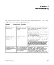
... the port at the hub. For instructions on the NETGEAR switch and the connected device are correct and comply with Ethernet specifications. No power is off . All fiber cables must be crossover cables for the switch and the connected device. Check for a defective adapter card, cable, or port by testing them in an alternate environment where all cables used are not the same. intermittent. Troubleshooting 5-1 Troubleshooting Information Symptom Cause Solution Power LED is a problem. Chapter 5 Troubleshooting...
... the port at the hub. For instructions on the NETGEAR switch and the connected device are correct and comply with Ethernet specifications. No power is off . All fiber cables must be crossover cables for the switch and the connected device. Check for a defective adapter card, cable, or port by testing them in an alternate environment where all cables used are not the same. intermittent. Troubleshooting 5-1 Troubleshooting Information Symptom Cause Solution Power LED is a problem. Chapter 5 Troubleshooting...
Installation Guide
Page 36
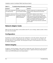
... environment are not properly connected or cabling does not meet Ethernet guidelines. Configuration If problems occur after altering the network configuration, restore the original connections and determine the problem by resetting the switch. Switch Integrity If required, verify the integrity of -sale representative. 5-2 Troubleshooting Straight-through cables should be used for the Model FS509 Fast Ethernet Switch Table 5-1. Make sure that the cabling is not recognized as part of the installation do not exceed the...
... environment are not properly connected or cabling does not meet Ethernet guidelines. Configuration If problems occur after altering the network configuration, restore the original connections and determine the problem by resetting the switch. Switch Integrity If required, verify the integrity of -sale representative. 5-2 Troubleshooting Straight-through cables should be used for the Model FS509 Fast Ethernet Switch Table 5-1. Make sure that the cabling is not recognized as part of the installation do not exceed the...


