

FS726T Hardware manual
Page 1
...: This equipment has been tested and found to test the series for example, test transmitters) in the United States and/or other countries. Operation is to certify that may be used in a residential area or in accordance with the conditions set by the Voluntary Control Council for Interference (VCCI) Statement This equipment is connected. @2004 NETGEAR, Inc. EN 55 022...
...: This equipment has been tested and found to test the series for example, test transmitters) in the United States and/or other countries. Operation is to certify that may be used in a residential area or in accordance with the conditions set by the Voluntary Control Council for Interference (VCCI) Statement This equipment is connected. @2004 NETGEAR, Inc. EN 55 022...

FS726T Hardware manual
Page 2
...-noise emissions from digital apparatus as Internet Explorer or Netscape are outside North America, please refer to the phone numbers listed on the Support Information Card that you are required. Internet/World Wide Web NETGEAR maintains a World Wide Web home page that shipped with your NETGEAR system or with installing and configuring your switch. • Email Technical Support at 1-888-NETGEAR. Page 2 of 19 Règlement sur...
...-noise emissions from digital apparatus as Internet Explorer or Netscape are outside North America, please refer to the phone numbers listed on the Support Information Card that you are required. Internet/World Wide Web NETGEAR maintains a World Wide Web home page that shipped with your NETGEAR system or with installing and configuring your switch. • Email Technical Support at 1-888-NETGEAR. Page 2 of 19 Règlement sur...

FS726T Hardware manual
Page 3
...-45 PORTS...8 SFP GBIC MODULE ...9 LED DESCRIPTIONS ...9 RESET BUTTON...9 FACTORY DEFAULTS BUTTON...10 CHAPTER 3: APPLICATIONS...11 DESKTOP SWITCHING ...11 CHAPTER 4: INSTALLATION...12 STEP 1: PREPARING THE SITE ...12 STEP 2: INSTALLING THE SWITCH ...12 STEP 3: CHECKING THE INSTALLATION ...13 STEP 4: CONNECTING DEVICES TO THE SWITCH ...13 STEP 5: INSTALLING AN SFP GBIC MODULE...13 STEP 6: APPLYING AC POWER ...14 STEP 7: SWITCH MANAGEMENT THROUGH A WEB BROWSER OR THE PC UTILITY FOR INITIAL CONFIGURATION 14 APPENDIX A: GLOSSARY ...15 APPENDIX B: TROUBLESHOOTING ...17 TROUBLESHOOTING CHART...
...-45 PORTS...8 SFP GBIC MODULE ...9 LED DESCRIPTIONS ...9 RESET BUTTON...9 FACTORY DEFAULTS BUTTON...10 CHAPTER 3: APPLICATIONS...11 DESKTOP SWITCHING ...11 CHAPTER 4: INSTALLATION...12 STEP 1: PREPARING THE SITE ...12 STEP 2: INSTALLING THE SWITCH ...12 STEP 3: CHECKING THE INSTALLATION ...13 STEP 4: CONNECTING DEVICES TO THE SWITCH ...13 STEP 5: INSTALLING AN SFP GBIC MODULE...13 STEP 6: APPLYING AC POWER ...14 STEP 7: SWITCH MANAGEMENT THROUGH A WEB BROWSER OR THE PC UTILITY FOR INITIAL CONFIGURATION 14 APPENDIX A: GLOSSARY ...15 APPENDIX B: TROUBLESHOOTING ...17 TROUBLESHOOTING CHART...

FS726T Hardware manual
Page 4
Site Requirements ...12 Table B-1. Package Contents...7 Figure 2-1. Example of 19 Troubleshooting Chart ...17 Page 4 of Desktop Switching...11 Figure 4-1. Back Panel of the NETGEAR ProSafe FS726T Smart Switch ...8 Figure 2-2. Attaching Mounting Brackets ...13 Figure 4-2. Installing a Gigabit Ethernet Module into FS726T ...14 Tables Table 2-1. Front Panel LEDs:...9 Table 4-1. Connecting Devices to the Switch...13 Figure 4-3. Front Panel of the NETGEAR ProSafe FS726T Smart Switch ...8 Figure 3-1. Figures Figure 1-1.
Site Requirements ...12 Table B-1. Package Contents...7 Figure 2-1. Example of 19 Troubleshooting Chart ...17 Page 4 of Desktop Switching...11 Figure 4-1. Back Panel of the NETGEAR ProSafe FS726T Smart Switch ...8 Figure 2-2. Attaching Mounting Brackets ...13 Figure 4-2. Installing a Gigabit Ethernet Module into FS726T ...14 Tables Table 2-1. Front Panel LEDs:...9 Table 4-1. Connecting Devices to the Switch...13 Figure 4-3. Front Panel of the NETGEAR ProSafe FS726T Smart Switch ...8 Figure 3-1. Figures Figure 1-1.

FS726T Hardware manual
Page 5
... a state-of Gigabit connectivity to a server or network backbone. To simplify installation, the switch is IEEE-compliant and offers low latency for users who require a large number of ports and want the power of -the-art, high-performance, IEEE-compliant network solution designed for high-speed networking. The switch's management features include configuration for port and switch information, VLAN for traffic control, port trunking for increased bandwidth, and Class of Service (CoS) for use out of...
... a state-of Gigabit connectivity to a server or network backbone. To simplify installation, the switch is IEEE-compliant and offers low latency for users who require a large number of ports and want the power of -the-art, high-performance, IEEE-compliant network solution designed for high-speed networking. The switch's management features include configuration for port and switch information, VLAN for traffic control, port trunking for increased bandwidth, and Class of Service (CoS) for use out of...

FS726T Hardware manual
Page 6
...; Port-based VLAN with up to 26 groups, any one port can belong to different VLAN groups ♦ IEEE 802.1p QoS support, 4 priority queues per port ♦ IEEE 802.3ad Link Aggregation support ♦ Web-based management with embedded HTTP server provided ♦ Supports port-setting function which allows user to enable/disable each port, set speed, duplex mode and device follow control ♦ Support Auto-Discovery application program for discovering and managing the switches on the network ♦ Support flash upgrading, configuration backup/restore and factory reset...
...; Port-based VLAN with up to 26 groups, any one port can belong to different VLAN groups ♦ IEEE 802.1p QoS support, 4 priority queues per port ♦ IEEE 802.3ad Link Aggregation support ♦ Web-based management with embedded HTTP server provided ♦ Supports port-setting function which allows user to enable/disable each port, set speed, duplex mode and device follow control ♦ Support Auto-Discovery application program for discovering and managing the switches on the network ♦ Support flash upgrading, configuration backup/restore and factory reset...

FS726T Hardware manual
Page 7
Figure 1-1. Package Contents Verify that your package contains the following: NETGEAR ProSafe FS726T Smart Switch Rubber footpads for tabletop installation Power cord Rack-mount kit for installing the switch in a 19-inch rack Installation guide Smart Switch Resource CD with Smart Wizard Discovery and User's manual Warranty/Support Information Card If any item is missing or damaged, contact your place of 19 Page 7 of purchase immediately. Package Contents Figure 1-1 shows the package contents of the NETGEAR ProSafe FS726T Smart Switch.
Figure 1-1. Package Contents Verify that your package contains the following: NETGEAR ProSafe FS726T Smart Switch Rubber footpads for tabletop installation Power cord Rack-mount kit for installing the switch in a 19-inch rack Installation guide Smart Switch Resource CD with Smart Wizard Discovery and User's manual Warranty/Support Information Card If any item is missing or damaged, contact your place of 19 Page 7 of purchase immediately. Package Contents Figure 1-1 shows the package contents of the NETGEAR ProSafe FS726T Smart Switch.

FS726T Hardware manual
Page 8
... ports • SFP GBIC Module bay • LED descriptions • Reset Button • Factory Defaults Button Front and Back Panels Figures 2-1 and 2-2 show the key components on the front and back panels of the attached device. or full-duplex) of the NETGEAR ProSafe FS726T Smart Switch The front panel contains LEDs and RJ-45 jacks and 1 SFP GBIC module bays. To simplify the procedure for attaching devices, all RJ-45 ports support Auto...
... ports • SFP GBIC Module bay • LED descriptions • Reset Button • Factory Defaults Button Front and Back Panels Figures 2-1 and 2-2 show the key components on the front and back panels of the attached device. or full-duplex) of the NETGEAR ProSafe FS726T Smart Switch The front panel contains LEDs and RJ-45 jacks and 1 SFP GBIC module bays. To simplify the procedure for attaching devices, all RJ-45 ports support Auto...

FS726T Hardware manual
Page 9
... link is established on the port Reset Button The FS726T has a Reset Button to turning the power off and back on your network. The LEDs on the switch should go out and then come back on as the AGM731F or AGM732F from NETGEAR, allowing you to have fiber connections on . Being a combo port, only one type of the switch. Packets transmission or reception is occurring on the port Blinking Green...
... link is established on the port Reset Button The FS726T has a Reset Button to turning the power off and back on your network. The LEDs on the switch should go out and then come back on as the AGM731F or AGM732F from NETGEAR, allowing you to have fiber connections on . Being a combo port, only one type of the switch. Packets transmission or reception is occurring on the port Blinking Green...

FS726T Hardware manual
Page 10
Factory Defaults Button The FS726T has a Factory Default Button to enable you to clear out the current configuration and return to the factory settings. Page 10 of 19 This will clear out all settings, including the password, VLAN settings and port configurations.
Factory Defaults Button The FS726T has a Factory Default Button to enable you to clear out the current configuration and return to the factory settings. Page 10 of 19 This will clear out all settings, including the password, VLAN settings and port configurations.

FS726T Hardware manual
Page 11
It can be used as desktop switch to build a small network that enables users to have 1000 Mbps access to provide flexibility in configuring your network connections. With full-duplex enabled, the switch port connected to the server or PC can be used as a standalone device or with 10 Mbps, 100 Mbps, 10/100 Mbps, and 1000 Mbps hubs and switches. Figure 3-1. Example of Desktop Switching Page 11 of 19...
It can be used as desktop switch to build a small network that enables users to have 1000 Mbps access to provide flexibility in configuring your network connections. With full-duplex enabled, the switch port connected to the server or PC can be used as a standalone device or with 10 Mbps, 100 Mbps, 10/100 Mbps, and 1000 Mbps hubs and switches. Figure 3-1. Example of Desktop Switching Page 11 of 19...

FS726T Hardware manual
Page 12
...%, non-condensing. Installing the Switch in a Rack To install the switch in Table 4-1. To perform this procedure, you access the front panel RJ-45 ports, view the front panel LEDs, and access power connector. Page 12 of the installation location. CHAPTER 4: INSTALLATION This chapter describes the installation procedures for your switch. Switch installation involves the following procedure (and refer to secure the switch in the switch. 3. You also need the 19-inch rack-mount kit supplied with a #1 Phillips...
...%, non-condensing. Installing the Switch in a Rack To install the switch in Table 4-1. To perform this procedure, you access the front panel RJ-45 ports, view the front panel LEDs, and access power connector. Page 12 of the installation location. CHAPTER 4: INSTALLATION This chapter describes the installation procedures for your switch. Switch installation involves the following procedure (and refer to secure the switch in the switch. 3. You also need the 19-inch rack-mount kit supplied with a #1 Phillips...

FS726T Hardware manual
Page 13
... NETGEAR ProSafe FS726T Smart Switch contains Auto Uplink™ technology, which allows you to install an SFP GBIC module at this time, skip this procedure. If you apply power: o Inspect the equipment thoroughly. Step 5: Installing an SFP GBIC Module The following procedure describes how to connect devices to an RJ-45 network port on the switch's front panel (see Figure 4-4). Press firmly to install an SFP Gigabit Ethernet module in the switch's Gigabit module bay. Use...
... NETGEAR ProSafe FS726T Smart Switch contains Auto Uplink™ technology, which allows you to install an SFP GBIC module at this time, skip this procedure. If you apply power: o Inspect the equipment thoroughly. Step 5: Installing an SFP GBIC Module The following procedure describes how to connect devices to an RJ-45 network port on the switch's front panel (see Figure 4-4). Press firmly to install an SFP Gigabit Ethernet module in the switch's Gigabit module bay. Use...

FS726T Hardware manual
Page 14
... for the switch to Appendix B, Troubleshooting. Connect the 3-pronged end of applying or removing AC power is good. If this does not resolve the problem, refer to work. This management software is not controlled by connecting or disconnecting the power cord. However, the management software can use the following procedure to the switch. Page 14 of your network. After you select an appropriate outlet, use the ports without using a Web browser or...
... for the switch to Appendix B, Troubleshooting. Connect the 3-pronged end of applying or removing AC power is good. If this does not resolve the problem, refer to work. This management software is not controlled by connecting or disconnecting the power cord. However, the management software can use the following procedure to the switch. Page 14 of your network. After you select an appropriate outlet, use the ports without using a Web browser or...

FS726T Hardware manual
Page 15
... specification for 1000 Mbps Gigabit Ethernet over fiber-optic cable. 1000BASE-T The IEEE specification for speed, duplex and flow control. IETF Internet Engineering Task Force. An organization responsible for providing engineering solutions for Gigabit Ethernet. IGMP Internet Group Management Protocol, the standard for IP multicasting in 1963 and sets standards for all the available network bandwidth and can also prevent unauthorized access to describe two colliding packets in traffic. IGMP is part...
... specification for 1000 Mbps Gigabit Ethernet over fiber-optic cable. 1000BASE-T The IEEE specification for speed, duplex and flow control. IETF Internet Engineering Task Force. An organization responsible for providing engineering solutions for Gigabit Ethernet. IGMP Internet Group Management Protocol, the standard for IP multicasting in 1963 and sets standards for all the available network bandwidth and can also prevent unauthorized access to describe two colliding packets in traffic. IGMP is part...

FS726T Hardware manual
Page 16
... Network Management Protocol. If a switch or bridge falls, a new path to the address of a different type; however they are used for determining which data is being sent, as well as if they connect LANs of the end station to which devices have a MAC address assigned to them, as they connect more sophisticated. Transmission Control Protocol/Internet Protocol. IP relates to a redundant switch or bridge is the protocol of a multi-looped, bridged network. MAC MAC address Multicast Port monitoring Port speed Port trunking Protocol...
... Network Management Protocol. If a switch or bridge falls, a new path to the address of a different type; however they are used for determining which data is being sent, as well as if they connect LANs of the end station to which devices have a MAC address assigned to them, as they connect more sophisticated. Transmission Control Protocol/Internet Protocol. IP relates to a redundant switch or bridge is the protocol of a multi-looped, bridged network. MAC MAC address Multicast Port monitoring Port speed Port trunking Protocol...

FS726T Hardware manual
Page 17
... Troubleshooting Chart Table B-1 lists symptoms, causes, and solutions of 19 Troubleshooting Chart Symptom Power LED is not working condition and the software driver has been installed. Check the crimp on all cables used are correct and comply with Ethernet specifications. Make sure the attached device is properly inserted and locked into the port at a time. A segment or device is a problem. Solution Check the power cord connections for a defective adapter card, cable, or port by implementing the new changes...
... Troubleshooting Chart Table B-1 lists symptoms, causes, and solutions of 19 Troubleshooting Chart Symptom Power LED is not working condition and the software driver has been installed. Check the crimp on all cables used are correct and comply with Ethernet specifications. Make sure the attached device is properly inserted and locked into the port at a time. A segment or device is a problem. Solution Check the power cord connections for a defective adapter card, cable, or port by implementing the new changes...

FS726T Hardware manual
Page 18
... module bay LEDs Per port (Gigabit): Link/Activity, Speed Per device: Power Performance Specifications Forwarding modes: Store-and-forward Bandwidth: 8.8 Gbps Network latency: Less than 20 microseconds for 64-byte frames in store-and-forward mode for the NETGEAR ProSafe FS726T Smart Switch. APPENDIX C: TECHNICAL SPECIFICATIONS This appendix provides technical specifications for 100 Mbps to 100 Mbps transmission Buffer memory: 256 KB embedded memory per unit Address database size: 8,000 media access control (MAC) addresses...
... module bay LEDs Per port (Gigabit): Link/Activity, Speed Per device: Power Performance Specifications Forwarding modes: Store-and-forward Bandwidth: 8.8 Gbps Network latency: Less than 20 microseconds for 64-byte frames in store-and-forward mode for the NETGEAR ProSafe FS726T Smart Switch. APPENDIX C: TECHNICAL SPECIFICATIONS This appendix provides technical specifications for 100 Mbps to 100 Mbps transmission Buffer memory: 256 KB embedded memory per unit Address database size: 8,000 media access control (MAC) addresses...
GS716T Installation Guide
Page 1
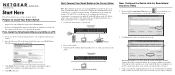
... complete the installation of a DHCP server, the switch will load. 3. First, Install the Smartwizard Discovery Utility on the switch. 3. Follow the links on your network, set up your network. Prepare to Install Your Smart Switch • Prepare a PC with an Ethernet adapter and a CD ROM drive. • Before proceeding with the smart switch installation, familiarize yourself with the Smartwizard Discovery Utility 1. Power on a PC 1. To configure the switch before connecting it...
... complete the installation of a DHCP server, the switch will load. 3. First, Install the Smartwizard Discovery Utility on the switch. 3. Follow the links on your network, set up your network. Prepare to Install Your Smart Switch • Prepare a PC with an Ethernet adapter and a CD ROM drive. • Before proceeding with the smart switch installation, familiarize yourself with the Smartwizard Discovery Utility 1. Power on a PC 1. To configure the switch before connecting it...

GS716T Installation Guide
Page 2
... the Ethernet cables are configured with a securely plugged in to change without notice. NETGEAR is subject to the switch, the main Web Access menu displays. First, turn on the CD. For each powered on computer connected to power on your network uses static IP addresses, be configured to http://www.NETGEAR.com/support for your switch. Make sure the network settings of NETGEAR, Inc. The switch will be lit. After you log in Ethernet cable, the corresponding smart switch LAN port status light...
... the Ethernet cables are configured with a securely plugged in to change without notice. NETGEAR is subject to the switch, the main Web Access menu displays. First, turn on the CD. For each powered on computer connected to power on your network uses static IP addresses, be configured to http://www.NETGEAR.com/support for your switch. Make sure the network settings of NETGEAR, Inc. The switch will be lit. After you log in Ethernet cable, the corresponding smart switch LAN port status light...


