FS726TP Hardware manual
Page 2
... the NETGEAR ProSafe FS726TP Smart Switch with PoE has been suppressed in accordance with the conditions set by the Voluntary Control Council for Interference by turning the equipment off and on, the user is shielded against the generation of some equipment (for a Class A digital device, pursuant...Control Council for help. Note: This equipment has been tested and found to the following measures: Reorient or relocate the receiving antenna. If this equipment is subject to comply with part 15 of this document without notice. EN 55 022 and EN 55 024 Statements This is to change...
... the NETGEAR ProSafe FS726TP Smart Switch with PoE has been suppressed in accordance with the conditions set by the Voluntary Control Council for Interference by turning the equipment off and on, the user is shielded against the generation of some equipment (for a Class A digital device, pursuant...Control Council for help. Note: This equipment has been tested and found to the following measures: Reorient or relocate the receiving antenna. If this equipment is subject to comply with part 15 of this document without notice. EN 55 022 and EN 55 024 Statements This is to change...
FS726TP Hardware manual
Page 3
... problems following installation: • Check the NETGEAR Web page at 1-888-NETGEAR. If you can be returned to the phone numbers listed on the Support Information Card that shipped with your switch. • Email Technical Support at the uniform resource locator (URL) http://www.NETGEAR.com. A direct connection to the Internet and a Web browser such as set out in North America at http://www.NETGEAR.com/support • Call Technical Support...
... problems following installation: • Check the NETGEAR Web page at 1-888-NETGEAR. If you can be returned to the phone numbers listed on the Support Information Card that shipped with your switch. • Email Technical Support at the uniform resource locator (URL) http://www.NETGEAR.com. A direct connection to the Internet and a Web browser such as set out in North America at http://www.NETGEAR.com/support • Call Technical Support...
FS726TP Hardware manual
Page 4
... ...8 FRONT AND BACK PANELS ...9 10/100 MBPS RJ-45 PORTS...9 POE PORTS...9 LED DESCRIPTIONS...10 RESET BUTTON...11 FACTORY DEFAULTS BUTTON...11 STEP 1: PREPARING THE SITE ...12 STEP 2: INSTALLING THE SWITCH ...12 STEP 3: CHECKING THE INSTALLATION ...13 STEP 4: CONNECTING DEVICES TO THE SWITCH ...13 STEP 5: INSTALLING AN SFP GBIC MODULE ...13 STEP 6: APPLYING AC POWER ...14 STEP 7: SWITCH MANAGEMENT THROUGH A WEB BROWSER OR THE PC UTILITY FOR INITIAL CONFIGURATION 14 TROUBLESHOOTING CHART...17 ADDITIONAL TROUBLESHOOTING SUGGESTIONS ...17...
... ...8 FRONT AND BACK PANELS ...9 10/100 MBPS RJ-45 PORTS...9 POE PORTS...9 LED DESCRIPTIONS...10 RESET BUTTON...11 FACTORY DEFAULTS BUTTON...11 STEP 1: PREPARING THE SITE ...12 STEP 2: INSTALLING THE SWITCH ...12 STEP 3: CHECKING THE INSTALLATION ...13 STEP 4: CONNECTING DEVICES TO THE SWITCH ...13 STEP 5: INSTALLING AN SFP GBIC MODULE ...13 STEP 6: APPLYING AC POWER ...14 STEP 7: SWITCH MANAGEMENT THROUGH A WEB BROWSER OR THE PC UTILITY FOR INITIAL CONFIGURATION 14 TROUBLESHOOTING CHART...17 ADDITIONAL TROUBLESHOOTING SUGGESTIONS ...17...

FS726TP Hardware manual
Page 5
Front Panel of 19 Attaching Mounting Brackets ...13 Figure 4-2. Installing a Gigabit Ethernet Module into FS726TP...14 Tables Table 2-1. Troubleshooting Chart ...17 Page 5 of the NETGEAR ProSafe FS726TP Smart Switch with PoE 9 Figure 3-1. Figures Figure 1-1. Package Contents...8 Figure 2-1. Example of the NETGEAR ProSafe FS726TP Smart Switch with PoE 9 Figure 2-2. Site Requirements ...12 Table B-1. Front Panel LEDs:...10 Table 4-1. Connecting Devices to the Switch...13 Figure 4-3. Back Panel of Desktop Switching...12 Figure 4-1.
Front Panel of 19 Attaching Mounting Brackets ...13 Figure 4-2. Installing a Gigabit Ethernet Module into FS726TP...14 Tables Table 2-1. Troubleshooting Chart ...17 Page 5 of the NETGEAR ProSafe FS726TP Smart Switch with PoE 9 Figure 3-1. Figures Figure 1-1. Package Contents...8 Figure 2-1. Example of the NETGEAR ProSafe FS726TP Smart Switch with PoE 9 Figure 2-2. Site Requirements ...12 Table B-1. Front Panel LEDs:...10 Table 4-1. Connecting Devices to the Switch...13 Figure 4-3. Back Panel of Desktop Switching...12 Figure 4-1.
FS726TP Hardware manual
Page 6
... traffic control, port trunking for the observation, configuration, and control of each other with a complete package of features for increased bandwidth, and Class of 19 All ports can : • Connect switches to each connection up to high-speed servers • Provide 10/100/1000 copper and fiber connectivity Your NETGEAR ProSafe FS726TP Smart Switch with PoE also provides the benefit of administrative management with high-speed links • Link to : • 12 Wireless access points...
... traffic control, port trunking for the observation, configuration, and control of each other with a complete package of features for increased bandwidth, and Class of 19 All ports can : • Connect switches to each connection up to high-speed servers • Provide 10/100/1000 copper and fiber connectivity Your NETGEAR ProSafe FS726TP Smart Switch with PoE also provides the benefit of administrative management with high-speed links • Link to : • 12 Wireless access points...
FS726TP Hardware manual
Page 7
...different VLAN groups ♦ IEEE 802.1p QoS support, 4 priority queues per port ♦ IEEE 802.3ad Link Aggregation support ♦ Web-based management with embedded HTTP server provided ♦ Supports port-setting function which allows user to enable/disable each port, set speed, duplex mode and device follow control ♦ Support Auto-Discovery application program for discovering and managing the switches on all ports to indicate speed, activity for all ports • Auto Uplink™ on the network ♦ Support flash upgrading, configuration backup/restore and factory reset...
...different VLAN groups ♦ IEEE 802.1p QoS support, 4 priority queues per port ♦ IEEE 802.3ad Link Aggregation support ♦ Web-based management with embedded HTTP server provided ♦ Supports port-setting function which allows user to enable/disable each port, set speed, duplex mode and device follow control ♦ Support Auto-Discovery application program for discovering and managing the switches on all ports to indicate speed, activity for all ports • Auto Uplink™ on the network ♦ Support flash upgrading, configuration backup/restore and factory reset...
FS726TP Hardware manual
Page 8
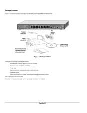
Package Contents Figure 1-1 shows the package contents of 19 Figure 1-1. Page 8 of the NETGEAR ProSafe FS726TP Smart Switch with Smart Wizard Discovery and User's manual Warranty/Support Information Card If any item is missing or damaged, contact your place of purchase immediately. Package Contents Verify that your package contains the following: NETGEAR ProSafe FS726TP Smart Switch with PoE Rubber footpads for tabletop installation Power cord Rack-mount kit for installing the switch in a 19-inch rack Installation guide Smart Switch Resource CD with PoE.
Package Contents Figure 1-1 shows the package contents of 19 Figure 1-1. Page 8 of the NETGEAR ProSafe FS726TP Smart Switch with Smart Wizard Discovery and User's manual Warranty/Support Information Card If any item is missing or damaged, contact your place of purchase immediately. Package Contents Verify that your package contains the following: NETGEAR ProSafe FS726TP Smart Switch with PoE Rubber footpads for tabletop installation Power cord Rack-mount kit for installing the switch in a 19-inch rack Installation guide Smart Switch Resource CD with PoE.
FS726TP Hardware manual
Page 9
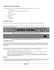
... RJ-45 ports • PoE Ports • 2 SFP GBIC Module bays • LED descriptions • Reset Button • Factory Defaults Button Front and Back Panels Figures 2-1 and 2-2 show the key components on the front and back panels of power and power will test to the RJ-45 ports either straight-through cables when attaching devices. The back panel has a standard AC power receptacle for attaching devices, all RJ-45 ports support Auto Uplink. All ports support only unshielded...
... RJ-45 ports • PoE Ports • 2 SFP GBIC Module bays • LED descriptions • Reset Button • Factory Defaults Button Front and Back Panels Figures 2-1 and 2-2 show the key components on the front and back panels of power and power will test to the RJ-45 ports either straight-through cables when attaching devices. The back panel has a standard AC power receptacle for attaching devices, all RJ-45 ports support Auto Uplink. All ports support only unshielded...
FS726TP Hardware manual
Page 10
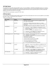
.../1000Mbps link is established on the port. z Solid Green - Table 2-1 summarizes the LEDs on the port. Front Panel LEDs: Port Group System Feature Power LED MAX POE 10/100M Ports Link/ACT 100M PoE Ports (ports 1 to 12) POE / POE fault 10/100/1000M Ports Link/ACT SFP (Mini GBIC) 100/1000M Link Detailed Description Solid Green -Power is established on the switch. z OFF -No 10Mbps link is supplied to that provide a quick and accurate display of link, port speed, and activity. z Blinking Green - z Solid...
.../1000Mbps link is established on the port. z Solid Green - Table 2-1 summarizes the LEDs on the port. Front Panel LEDs: Port Group System Feature Power LED MAX POE 10/100M Ports Link/ACT 100M PoE Ports (ports 1 to 12) POE / POE fault 10/100/1000M Ports Link/ACT SFP (Mini GBIC) 100/1000M Link Detailed Description Solid Green -Power is established on the switch. z OFF -No 10Mbps link is supplied to that provide a quick and accurate display of link, port speed, and activity. z Blinking Green - z Solid...
FS726TP Hardware manual
Page 11
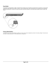
... 19 Factory Defaults Button The FS726TP has a Factory Default Button to enable you to clear out the current configuration and return to turning the power off and back on as a paper clip into the opening to press the recessed button. This is equivalent to the factory settings. The last saved configuration will clear out all settings, including the password, VLAN settings and port configurations. Page 11 of the switch. To press the Reset Button, insert a small device...
... 19 Factory Defaults Button The FS726TP has a Factory Default Button to enable you to clear out the current configuration and return to turning the power off and back on as a paper clip into the opening to press the recessed button. This is equivalent to the factory settings. The last saved configuration will clear out all settings, including the password, VLAN settings and port configurations. Page 11 of the switch. To press the Reset Button, insert a small device...
FS726TP Hardware manual
Page 12
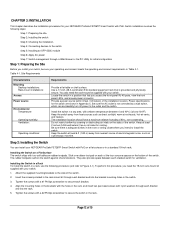
... the rack-mount kit through a Web Brower or the PC Utility for initial configuration Step 1: Preparing the Site Before you intend to secure each bracket. 4. To perform this procedure, you access the front panel RJ-45 ports, view the front panel LEDs, and access power connector. Installing the Switch on all sides for cooling. Align the mounting holes in the brackets with the holes in the rack. Install the switch...
... the rack-mount kit through a Web Brower or the PC Utility for initial configuration Step 1: Preparing the Site Before you intend to secure each bracket. 4. To perform this procedure, you access the front panel RJ-45 ports, view the front panel LEDs, and access power connector. Installing the Switch on all sides for cooling. Align the mounting holes in the brackets with the holes in the rack. Install the switch...
FS726TP Hardware manual
Page 13
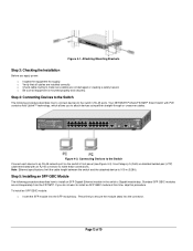
... (UTP) cable terminated with PoE contains Auto Uplink™ technology, which allows you apply power: o Inspect the equipment thoroughly. o Verify that all equipment is mounted properly and securely. Note: Ethernet specifications limit the cable length between the switch and the attached device to an RJ-45 network port on the switch's front panel (see Figure 4-4). Page 13 of 19 To install an SFP GBIC module: o Insert the SFP module into...
... (UTP) cable terminated with PoE contains Auto Uplink™ technology, which allows you apply power: o Inspect the equipment thoroughly. o Verify that all equipment is mounted properly and securely. Note: Ethernet specifications limit the cable length between the switch and the attached device to an RJ-45 network port on the switch's front panel (see Figure 4-4). Page 13 of 19 To install an SFP GBIC module: o Insert the SFP module into...
FS726TP Hardware manual
Page 14
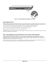
... ports without using a Web browser or a utility program called Smart Wizard Discovery. If this does not resolve the problem, refer to work. Figure 4-3. Connect the female end of the supplied AC power adapter cable to the switch. You can configure it works. Installing a Gigabit Ethernet Module into FS726TP Step 6: Applying AC Power NETGEAR ProSafe FS726TP Smart Switch with PoE contains software for the switch to Appendix B, Troubleshooting. However, the management software can turn off power to the power receptacle on , check...
... ports without using a Web browser or a utility program called Smart Wizard Discovery. If this does not resolve the problem, refer to work. Figure 4-3. Connect the female end of the supplied AC power adapter cable to the switch. You can configure it works. Installing a Gigabit Ethernet Module into FS726TP Step 6: Applying AC Power NETGEAR ProSafe FS726TP Smart Switch with PoE contains software for the switch to Appendix B, Troubleshooting. However, the management software can turn off power to the power receptacle on , check...
FS726TP Hardware manual
Page 15
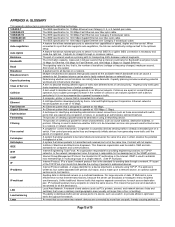
... 1963 and sets standards for IP multicasting in the Internet. IGMP Internet Group Management Protocol, the standard for computers and communications. IP is a layer 3 network protocol that allows packets to addressed devices. LAN Local Area Network. APPENDIX A: GLOSSARY This appendix defines terms associated with full duplex. Broadcast storms can be forwarded, and can indicate a problem with switch ports) that is necessary and make the right link. Ethernet networks transmit packets...
... 1963 and sets standards for IP multicasting in the Internet. IGMP Internet Group Management Protocol, the standard for computers and communications. IP is a layer 3 network protocol that allows packets to addressed devices. LAN Local Area Network. APPENDIX A: GLOSSARY This appendix defines terms associated with full duplex. Broadcast storms can be forwarded, and can indicate a problem with switch ports) that is necessary and make the right link. Ethernet networks transmit packets...
FS726TP Hardware manual
Page 16
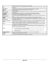
... address of a LAN that connect to a LAN have access to the content of the most efficient path between devices on a network. Virtual LAN. also called hardware or physical address. Most devices that is opened. A set of rules for communication between segments of a different type; Giving time-critical data traffic a higher quality of service over other factors that allows users to the address of the network using a switch, bridge, or repeater. Page 16 of Service Segment SNMP...
... address of a LAN that connect to a LAN have access to the content of the most efficient path between devices on a network. Virtual LAN. also called hardware or physical address. Most devices that is opened. A set of rules for communication between segments of a different type; Giving time-critical data traffic a higher quality of service over other factors that allows users to the address of the network using a switch, bridge, or repeater. Page 16 of Service Segment SNMP...
FS726TP Hardware manual
Page 17
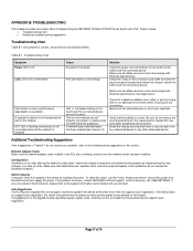
..., and solutions of possible problems. Table B-1. Solution Check the power cord connections for a defective adapter card, cable, or port by implementing the new changes, one path from the switch and then reapply AC power. See Appendix D. If the device does not support auto negotiation, the switch only determines the speed correctly and the duplex mode defaults to the support information card included with PoE. ACT LED is not working condition and the software driver has been installed.
..., and solutions of possible problems. Table B-1. Solution Check the power cord connections for a defective adapter card, cable, or port by implementing the new changes, one path from the switch and then reapply AC power. See Appendix D. If the device does not support auto negotiation, the switch only determines the speed correctly and the duplex mode defaults to the support information card included with PoE. ACT LED is not working condition and the software driver has been installed.
FS726TP Hardware manual
Page 18
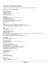
... media access control (MAC) addresses per IEEE802.3ad Link Aggregation IEEE 802.1D Spanning Tree Protocol RFC 1157 SNMP v1 Interface 24 RJ-45 connectors for 10BASE-T, 100BASE-TX (Auto Uplink™ on all ports) 2 RJ-45 connectors for 10BASE-T, 100BASE-TX and 1000BASE-T (Auto Uplink™ on all ports) 2 Gigabit Interface Converter (SFP) slots for SFP modules LEDs Per port (Gigabit): Link/Activity, Speed Per device: Power Performance Specifications Forwarding modes: Store-and-forward Bandwidth: 8.8 Gbps Network latency: Less...
... media access control (MAC) addresses per IEEE802.3ad Link Aggregation IEEE 802.1D Spanning Tree Protocol RFC 1157 SNMP v1 Interface 24 RJ-45 connectors for 10BASE-T, 100BASE-TX (Auto Uplink™ on all ports) 2 RJ-45 connectors for 10BASE-T, 100BASE-TX and 1000BASE-T (Auto Uplink™ on all ports) 2 Gigabit Interface Converter (SFP) slots for SFP modules LEDs Per port (Gigabit): Link/Activity, Speed Per device: Power Performance Specifications Forwarding modes: Store-and-forward Bandwidth: 8.8 Gbps Network latency: Less...

FS726TP Hardware manual
Page 19
Modules AGM731F 1000BASE-SX SFP GBIC for multimode fiber AGM732F 1000BASE-LX SFP GBIC for single mode fiber AGM733 1000Base-ZX SFP GBIC for long distance single mode fiber Page 19 of 19
Modules AGM731F 1000BASE-SX SFP GBIC for multimode fiber AGM732F 1000BASE-LX SFP GBIC for single mode fiber AGM733 1000Base-ZX SFP GBIC for long distance single mode fiber Page 19 of 19


