
GS110TP Hardware Installation Guide
Page 2
... Part Number: Publication Version Number: GS110TP March 2010 Gigabit Advanced Smart Switch GS110TP Smart PoE Switch Business English 202-10596-01 1.0 ii v1.0, March 2010 All rights reserved. Portions of this document are trademarks or registered trademarks of this document without notice. The operation of some equipment (for Telecommunications Approvals has been notified of the placing of NETGEAR, Inc. Trademarks NETGEAR, the NETGEAR logo, and Auto...
... Part Number: Publication Version Number: GS110TP March 2010 Gigabit Advanced Smart Switch GS110TP Smart PoE Switch Business English 202-10596-01 1.0 ii v1.0, March 2010 All rights reserved. Portions of this document are trademarks or registered trademarks of this document without notice. The operation of some equipment (for Telecommunications Approvals has been notified of the placing of NETGEAR, Inc. Trademarks NETGEAR, the NETGEAR logo, and Auto...

GS110TP Hardware Installation Guide
Page 4
... Step 1: Preparing the Site 4-1 Step 2: Installing the Switch 4-2 Installing the Switch on a Flat Surface 4-2 Wall Mounting the Switch 4-2 Step 3: Checking the Installation 4-3 Step 4: Connecting Devices to the Switch 4-3 Step 5: Applying AC Power 4-4 Step 6: Managing the Switch using a Web Browser or the PC Utility 4-4 Appendix A Troubleshooting Troubleshooting Chart A-1 Additional Troubleshooting Suggestions A-2 Network Adapter Cards A-2 Configuration ...A-2 Switch Integrity ...A-2 Auto-Negotiation ...A-3 Appendix B Technical Specifications Index iv Contents v1.0, March 2010
... Step 1: Preparing the Site 4-1 Step 2: Installing the Switch 4-2 Installing the Switch on a Flat Surface 4-2 Wall Mounting the Switch 4-2 Step 3: Checking the Installation 4-3 Step 4: Connecting Devices to the Switch 4-3 Step 5: Applying AC Power 4-4 Step 6: Managing the Switch using a Web Browser or the PC Utility 4-4 Appendix A Troubleshooting Troubleshooting Chart A-1 Additional Troubleshooting Suggestions A-2 Network Adapter Cards A-2 Configuration ...A-2 Switch Integrity ...A-2 Auto-Negotiation ...A-3 Appendix B Technical Specifications Index iv Contents v1.0, March 2010

GS110TP Hardware Installation Guide
Page 5
... damage to install and power on the GS110TP Smart PoE Switch. Conventions, Formats, and Scope The conventions, formats, and scope of note may result in the following typographical conventions: Italic Bold Fixed italic Emphasis, books, CDs, file and server names, extensions User input, IP addresses, GUI screen text Command prompt, CLI text, code URL links • Formats. Warning: Ignoring this type of this manual is...
... damage to install and power on the GS110TP Smart PoE Switch. Conventions, Formats, and Scope The conventions, formats, and scope of note may result in the following typographical conventions: Italic Bold Fixed italic Emphasis, books, CDs, file and server names, extensions User input, IP addresses, GUI screen text Command prompt, CLI text, code URL links • Formats. Warning: Ignoring this type of this manual is...
GS110TP Hardware Installation Guide
Page 6
... printer supports printing two pages on the NETGEAR, Inc. Failure to take heed of this feature. Revision History Part Number Version Number Date 202-10596-01 1.0 March 2010 Description Initial release vi About This Manual v1.0, March 2010 GS110TP Hardware Installation Guide Danger: This is written for the GS110TP Smart PoE Switch according to these specifications: Product Version Manual Publication Date GS110TP Smart PoE Switch March 2010 Note: Product updates are...
... printer supports printing two pages on the NETGEAR, Inc. Failure to take heed of this feature. Revision History Part Number Version Number Date 202-10596-01 1.0 March 2010 Description Initial release vi About This Manual v1.0, March 2010 GS110TP Hardware Installation Guide Danger: This is written for the GS110TP Smart PoE Switch according to these specifications: Product Version Manual Publication Date GS110TP Smart PoE Switch March 2010 Note: Product updates are...
GS110TP Hardware Installation Guide
Page 7
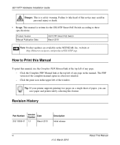
...-port switch with a complete package of your NETGEAR GS110TP Smart PoE Switch. Chapter 1 Introduction Congratulations on a PC. 1-1 v1.0, March 2010 The switch's management features include configuration for port and switch information, VLAN for traffic control, port trunking for increased bandwidth, and Class of the network. With a Web-based Graphical User Interface (GUI), the switch's many capabilities can be viewed and used in a simple and intuitive manner. This product offers support for traffic prioritization. For example: • Linking to a server...
...-port switch with a complete package of your NETGEAR GS110TP Smart PoE Switch. Chapter 1 Introduction Congratulations on a PC. 1-1 v1.0, March 2010 The switch's management features include configuration for port and switch information, VLAN for traffic control, port trunking for increased bandwidth, and Class of the network. With a Web-based Graphical User Interface (GUI), the switch's many capabilities can be viewed and used in a simple and intuitive manner. This product offers support for traffic prioritization. For example: • Linking to a server...

GS110TP Hardware Installation Guide
Page 8
... maximum segment length is a free-standing switch. Features The following list identifies the key features of Ethernet, Fast Ethernet, or Gigabit Ethernet devices. The table contains up to 4K Media Access Control (MAC) addresses. • Store-and-Forward transmission to remove bad packets from the network. • Full-duplex IEEE 802.3x pause frame flow control. • Active flow control to the highest speed. GS110TP Hardware Installation Guide The GS110TP Smart PoE Switch is 328 feet (100...
... maximum segment length is a free-standing switch. Features The following list identifies the key features of Ethernet, Fast Ethernet, or Gigabit Ethernet devices. The table contains up to 4K Media Access Control (MAC) addresses. • Store-and-Forward transmission to remove bad packets from the network. • Full-duplex IEEE 802.3x pause frame flow control. • Active flow control to the highest speed. GS110TP Hardware Installation Guide The GS110TP Smart PoE Switch is 328 feet (100...

GS110TP Hardware Installation Guide
Page 9
... features: • Ports 1 through 8 support IEEE 802.3af, Alternative A (MDI-X). • PoE is down automatically when the port link is enabled by default. Introduction 1-3 v1.0, March 2010 Green Features The GS110TP Smart PoE Switch supports the following power-saving features: • The power consumption automatically adjusts based on the RJ-45 cable length. • Each port is configured to power down . GS110TP Hardware Installation Guide • Standard NETGEAR 1xx series chassis. • NETGEAR Green product features. •...
... features: • Ports 1 through 8 support IEEE 802.3af, Alternative A (MDI-X). • PoE is down automatically when the port link is enabled by default. Introduction 1-3 v1.0, March 2010 Green Features The GS110TP Smart PoE Switch supports the following power-saving features: • The power consumption automatically adjusts based on the RJ-45 cable length. • Each port is configured to power down . GS110TP Hardware Installation Guide • Standard NETGEAR 1xx series chassis. • NETGEAR Green product features. •...
GS110TP Hardware Installation Guide
Page 11
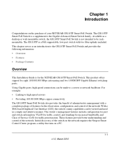
... the device • Recessed default reset button to restore the device back to the factory defaults • Link, Speed, and Activity LEDs for each port 2-1 v1.0, March 2010 Topics include: • GS110TP Front and Back Panel Configuration • LED Designations • Device Hardware Interfaces GS110TP Front and Back Panel Configuration The GS110TP Smart PoE Switch has eight 10/100/1000 Mbps autosensing and two 1000 Mbps SFP Gigabit Ethernet switching ports. Chapter 2 Physical Description This chapter describes the NETGEAR GS110TP Smart PoE Switch hardware features...
... the device • Recessed default reset button to restore the device back to the factory defaults • Link, Speed, and Activity LEDs for each port 2-1 v1.0, March 2010 Topics include: • GS110TP Front and Back Panel Configuration • LED Designations • Device Hardware Interfaces GS110TP Front and Back Panel Configuration The GS110TP Smart PoE Switch has eight 10/100/1000 Mbps autosensing and two 1000 Mbps SFP Gigabit Ethernet switching ports. Chapter 2 Physical Description This chapter describes the NETGEAR GS110TP Smart PoE Switch hardware features...
GS110TP Hardware Installation Guide
Page 12
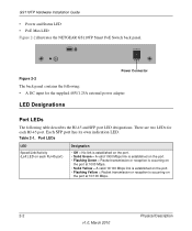
... Mbps. • Solid Yellow = A valid 10/100 Mbps link is established on the port. • Flashing Yellow = Packet transmission or reception is occurring on each RJ-45 port. There are two LEDs for the supplied 48V/1.25A external power adapter LED Designations Port LEDs The following table describes the RJ-45 and SFP port LED designations. GS110TP Hardware Installation Guide • Power and Status LED • PoE Max LED Figure 2-2 illustrates the NETGEAR GS110TP Smart PoE Switch back panel.
... Mbps. • Solid Yellow = A valid 10/100 Mbps link is established on the port. • Flashing Yellow = Packet transmission or reception is occurring on each RJ-45 port. There are two LEDs for the supplied 48V/1.25A external power adapter LED Designations Port LEDs The following table describes the RJ-45 and SFP port LED designations. GS110TP Hardware Installation Guide • Power and Status LED • PoE Max LED Figure 2-2 illustrates the NETGEAR GS110TP Smart PoE Switch back panel.

GS110TP Hardware Installation Guide
Page 13
... LED designations. All ports support only unshielded twisted-pair (UTP) cable terminated with an 8-pin RJ-45 plug. PoE power demand exceeds power available. - System LEDs The following failures resulted in the previous two minutes. GS110TP Hardware Installation Guide Table 2-1. Port LEDs (continued) LED PoE Status (Right LED on each RJ-45 port) SFP Port Indicate LED Designation • Off = No PoE powered device (PD) connected. • Solid Green = The PoE PD is connected and the port is available. • Flashing Yellow = The PoE...
... LED designations. All ports support only unshielded twisted-pair (UTP) cable terminated with an 8-pin RJ-45 plug. PoE power demand exceeds power available. - System LEDs The following failures resulted in the previous two minutes. GS110TP Hardware Installation Guide Table 2-1. Port LEDs (continued) LED PoE Status (Right LED on each RJ-45 port) SFP Port Indicate LED Designation • Off = No PoE powered device (PD) connected. • Solid Green = The PoE PD is connected and the port is available. • Flashing Yellow = The PoE...

GS110TP Hardware Installation Guide
Page 14
... is loaded into the opening to its Power On Self Test (POST). The last saved configuration is equivalent to the RJ-45 ports with the attached device, without requiring user intervention. Factory Defaults Button The Smart Switch has a Factory Defaults button on the front panel to allow you enable the Factory Defaults button, all RJ-45 ports support Auto Uplink. To operate the Factory Defaults button, insert a device such as the switch performs its factory settings. When inserting a cable into the switch...
... is loaded into the opening to its Power On Self Test (POST). The last saved configuration is equivalent to the RJ-45 ports with the attached device, without requiring user intervention. Factory Defaults Button The Smart Switch has a Factory Defaults button on the front panel to allow you enable the Factory Defaults button, all RJ-45 ports support Auto Uplink. To operate the Factory Defaults button, insert a device such as the switch performs its factory settings. When inserting a cable into the switch...
GS110TP Hardware Installation Guide
Page 15
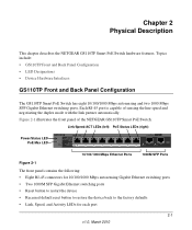
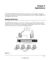
Internet Server Firewall PoE Max Link/Act PoE Link/Act Mode Green=Link at 1000M Yellow=Link at 100M/10M Blink=ACT PoE Mode Green=PoE Powered Yellow=PoE Fault PoE Ports PROSAFE GS110TP 9F 10F Link/Act Link/Act Figure 3-1 ` ` ` ` Desktop PCs 3-1 v1.0, March 2010 Desktop Switching The GS110TP Smart PoE Switch can be used as a desktop switch to build a small network that enables users to have 1000 Mbps access to a file server. It can be used as a stand-alone device or with 10 Mbps, 100 Mbps...
Internet Server Firewall PoE Max Link/Act PoE Link/Act Mode Green=Link at 1000M Yellow=Link at 100M/10M Blink=ACT PoE Mode Green=PoE Powered Yellow=PoE Fault PoE Ports PROSAFE GS110TP 9F 10F Link/Act Link/Act Figure 3-1 ` ` ` ` Desktop PCs 3-1 v1.0, March 2010 Desktop Switching The GS110TP Smart PoE Switch can be used as a desktop switch to build a small network that enables users to have 1000 Mbps access to a file server. It can be used as a stand-alone device or with 10 Mbps, 100 Mbps...
GS110TP Hardware Installation Guide
Page 17
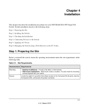
... meets the site requirements in the following table. You also need the mounting screws supplied with your NETGEAR GS110TP Smart PoE Switch. Site Requirements Characteristics Requirements Mounting Access • Desktop installations - Wall-mount: select a location. Switch installation involves the following steps: Step 1: Preparing the Site Step 2: Installing the Switch Step 3: Checking the Installation Step 4: Connecting Devices to the front panel RJ-45 ports, view the front panel LEDs, and access the power connector. 4-1 v1.0, March 2010
... meets the site requirements in the following table. You also need the mounting screws supplied with your NETGEAR GS110TP Smart PoE Switch. Site Requirements Characteristics Requirements Mounting Access • Desktop installations - Wall-mount: select a location. Switch installation involves the following steps: Step 1: Preparing the Site Step 2: Installing the Switch Step 3: Checking the Installation Step 4: Connecting Devices to the front panel RJ-45 ports, view the front panel LEDs, and access the power connector. 4-1 v1.0, March 2010

GS110TP Hardware Installation Guide
Page 19
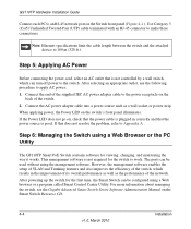
... Blink=ACT PoE Mode Green=PoE Powered Yellow=PoE Fault PoE Ports PROSAFE GS110TP Link/Act 9F Link/Act 10F ` ` Figure 4-1 Desktop PC Desktop PC Installation 4-3 v1.0, March 2010 Step 3: Checking the Installation GS110TP Hardware Installation Guide Before applying power to the switch, perform the following procedure describes how to connect PCs to make sure cables are installed correctly. • Check cable routing to the switch's RJ-45 ports. The GS110TP Smart PoE Switch contains Auto Uplink technology, which allows the attaching of devices using...
... Blink=ACT PoE Mode Green=PoE Powered Yellow=PoE Fault PoE Ports PROSAFE GS110TP Link/Act 9F Link/Act 10F ` ` Figure 4-1 Desktop PC Desktop PC Installation 4-3 v1.0, March 2010 Step 3: Checking the Installation GS110TP Hardware Installation Guide Before applying power to the switch, perform the following procedure describes how to connect PCs to make sure cables are installed correctly. • Check cable routing to the switch's RJ-45 ports. The GS110TP Smart PoE Switch contains Auto Uplink technology, which allows the attaching of devices using...
GS110TP Hardware Installation Guide
Page 20
... switch for viewing, changing, and monitoring the way it works. GS110TP Hardware Installation Guide Connect each PC to the power receptacle on the back of the switch. 2. Connect the end of the supplied IEC AC power adapter cable to an RJ-45 network port on the Switch front panel (Figure 4-1 ). For more information about managing the switch, see the Gigabit Advanced Smart Switch Series Software Administration Manual on the switch's front panel illuminates. Note: Ethernet specifications limit the cable length between the switch...
... switch for viewing, changing, and monitoring the way it works. GS110TP Hardware Installation Guide Connect each PC to the power receptacle on the back of the switch. 2. Connect the end of the supplied IEC AC power adapter cable to an RJ-45 network port on the Switch front panel (Figure 4-1 ). For more information about managing the switch, see the Gigabit Advanced Smart Switch Series Software Administration Manual on the switch's front panel illuminates. Note: Ethernet specifications limit the cable length between the switch...

GS110TP Hardware Installation Guide
Page 23
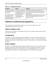
... connections, the ON/OFF switch, and the connected device. Port connection is a problem. File transfer is slow or performance degradation is not working. No power is set to autonegotiate. Make sure the attached device is received. Topics include the following: • Troubleshooting Chart • Additional Troubleshooting Suggestions Troubleshooting Chart The following table lists symptoms, causes, and solutions of possible problems. Table A-1. Check the crimp on the switch and the connected device are functioning. Link LED...
... connections, the ON/OFF switch, and the connected device. Port connection is a problem. File transfer is slow or performance degradation is not working. No power is set to autonegotiate. Make sure the attached device is received. Topics include the following: • Troubleshooting Chart • Additional Troubleshooting Suggestions Troubleshooting Chart The following table lists symptoms, causes, and solutions of possible problems. Table A-1. Check the crimp on the switch and the connected device are functioning. Link LED...
GS110TP Hardware Installation Guide
Page 24
GS110TP Hardware Installation Guide Table A-1. Ensure all connected ports and the network is disabled. ACT LED is not recognized as part of North America, please refer to the support information card included with your product. Network Adapter Cards Ensure the network adapter cards installed in the PCs are not properly connected, or cabling does not meet Ethernet guidelines. In North America, call 1-888-NETGEAR. If you are securely positioned in this section. Troubleshooting Chart Symptom Cause Solution A segment...
GS110TP Hardware Installation Guide Table A-1. Ensure all connected ports and the network is disabled. ACT LED is not recognized as part of North America, please refer to the support information card included with your product. Network Adapter Cards Ensure the network adapter cards installed in the PCs are not properly connected, or cabling does not meet Ethernet guidelines. In North America, call 1-888-NETGEAR. If you are securely positioned in this section. Troubleshooting Chart Symptom Cause Solution A segment...

GS110TP Hardware Installation Guide
Page 27
... VLAN IEEE 802.3ad Link Aggregation IEEE 802.1D Spanning Tree Protocol IEEE 802.1w Rapid Spanning Tree Protocol IEEE 802.1X Port Security IEEE 802.3AB LLDP SNMP v1, v2c, and v3 HTTP and HTTPS Port Mirroring (RX, TX, and Both) IGMP Snooping v1/v2 IEEE 802.1p Class of Service (CoS) SNTP (Simple Network Time Protocol) 2 servers. Disabled by default. Jumbo Frame Support Technical Specifications...
... VLAN IEEE 802.3ad Link Aggregation IEEE 802.1D Spanning Tree Protocol IEEE 802.1w Rapid Spanning Tree Protocol IEEE 802.1X Port Security IEEE 802.3AB LLDP SNMP v1, v2c, and v3 HTTP and HTTPS Port Mirroring (RX, TX, and Both) IGMP Snooping v1/v2 IEEE 802.1p Class of Service (CoS) SNTP (Simple Network Time Protocol) 2 servers. Disabled by default. Jumbo Frame Support Technical Specifications...
GS110TP Hardware Installation Guide
Page 28
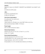
GS110TP Hardware Installation Guide Interface Eight RJ-45 connectors for 10BASE-T, 100BASE-TX, and 1000BASE-T (Auto Uplink™ on all ports) Two SFP slots for SFP modules LEDs Per RJ-45 port: Speed/Link/Activity Per SFP port: SFP indicator Performance Specifications Forwarding modes: Store-and-forward Bandwidth: 20 Gbps Address database size: 4K media access control (MAC) addresses per system Mean Time Between Failure (MTBF): 157,004 hours Power Supply 48V/1.25A 60W external power adapter Physical Specifications Dimensions (H x W x D): 236 x 101.6 x 27 mm...
GS110TP Hardware Installation Guide Interface Eight RJ-45 connectors for 10BASE-T, 100BASE-TX, and 1000BASE-T (Auto Uplink™ on all ports) Two SFP slots for SFP modules LEDs Per RJ-45 port: Speed/Link/Activity Per SFP port: SFP indicator Performance Specifications Forwarding modes: Store-and-forward Bandwidth: 20 Gbps Address database size: 4K media access control (MAC) addresses per system Mean Time Between Failure (MTBF): 157,004 hours Power Supply 48V/1.25A 60W external power adapter Physical Specifications Dimensions (H x W x D): 236 x 101.6 x 27 mm...

GS110TP Hardware Installation Guide
Page 31
...Pair 1-2 Checking the Installation 4-3 Class of Service 1-1 Connecting Devices to the Switch 4-3 Copper 1-1 Crossover 2-4 D Default IP Address 4-5 Default Reset Button 2-1 Desktop Switching 3-1 Device Hardware Interfaces 2-2 Duplex Mode 2-3 E Example of Desktop Switching 3-1 F Factory Default Button 2-4 Factory Defaults 2-1 Flat Surface 4-2 Full-duplex 1-2 G Gigabit Ports 1-1 H High-speed Servers 1-1 I IEEE 802.3i 1-2 IEEE 802.3x 1-2 IEEE Standards 1-2 IEEE-compliant 1-2 Installation Guide 1-4 Installing the Switch 4-2 L LED Designations 2-2 Low Latency 1-2 M MAC 1-2 Media Access Control...
...Pair 1-2 Checking the Installation 4-3 Class of Service 1-1 Connecting Devices to the Switch 4-3 Copper 1-1 Crossover 2-4 D Default IP Address 4-5 Default Reset Button 2-1 Desktop Switching 3-1 Device Hardware Interfaces 2-2 Duplex Mode 2-3 E Example of Desktop Switching 3-1 F Factory Default Button 2-4 Factory Defaults 2-1 Flat Surface 4-2 Full-duplex 1-2 G Gigabit Ports 1-1 H High-speed Servers 1-1 I IEEE 802.3i 1-2 IEEE 802.3x 1-2 IEEE Standards 1-2 IEEE-compliant 1-2 Installation Guide 1-4 Installing the Switch 4-2 L LED Designations 2-2 Low Latency 1-2 M MAC 1-2 Media Access Control...


