GS110TP Hardware Installation Guide
Page 12
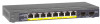
...Left LED on the port at 10/100 Mbps. 2-2 Physical Description v1.0, March 2010 GS110TP Hardware Installation Guide • Power and Status LED • PoE Max LED Figure 2-2 illustrates the NETGEAR GS110TP Smart PoE Switch back panel. Power Connector Figure 2-2 The back panel contains the following: • A DC input for...• Flashing Yellow = Packet transmission or reception is occurring on each RJ-45 port. There are two LEDs for the supplied 48V/1.25A external power adapter LED Designations Port LEDs The following table describes the RJ-45 and SFP port LED designations.
...Left LED on the port at 10/100 Mbps. 2-2 Physical Description v1.0, March 2010 GS110TP Hardware Installation Guide • Power and Status LED • PoE Max LED Figure 2-2 illustrates the NETGEAR GS110TP Smart PoE Switch back panel. Power Connector Figure 2-2 The back panel contains the following: • A DC input for...• Flashing Yellow = Packet transmission or reception is occurring on each RJ-45 port. There are two LEDs for the supplied 48V/1.25A external power adapter LED Designations Port LEDs The following table describes the RJ-45 and SFP port LED designations.

GS110TP Hardware Installation Guide
Page 13
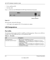
System LEDs The following failures resulted in the previous two minutes. GS110TP Hardware Installation Guide Table 2-1. System LEDs LED Power/Status LED PoE MAX LED Designation • Solid Green = Power is supplied to that port: - When inserting a cable into an RJ-45 port, the switch ...Solid Yellow = The switch is booting. • Off = Power is disconnected. • Off = There is at least 7W of PoE power available for another device. • Solid Yellow = Less than 7W of PoE power is supplying power successfully. • Flashing Yellow = One of the following table...
System LEDs The following failures resulted in the previous two minutes. GS110TP Hardware Installation Guide Table 2-1. System LEDs LED Power/Status LED PoE MAX LED Designation • Solid Green = Power is supplied to that port: - When inserting a cable into an RJ-45 port, the switch ...Solid Yellow = The switch is booting. • Off = Power is disconnected. • Off = There is at least 7W of PoE power available for another device. • Solid Yellow = Less than 7W of PoE power is supplying power successfully. • Flashing Yellow = One of the following table...
GS110TP Hardware Installation Guide
Page 17
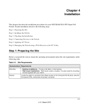
... environment meets the site requirements in a position that allows access to the front panel RJ-45 ports, view the front panel LEDs, and access the power connector. 4-1 v1.0, March 2010 Site Requirements Characteristics Requirements Mounting Access • Desktop installations - Wall-mount: select a location. Chapter 4 Installation This chapter describes the .... Locate the switch in the following table. Table 4-1. Provide a flat table or shelf surface. • Wall-mount installations - You also need the mounting screws supplied with your NETGEAR GS110TP Smart PoE Switch.
... environment meets the site requirements in a position that allows access to the front panel RJ-45 ports, view the front panel LEDs, and access the power connector. 4-1 v1.0, March 2010 Site Requirements Characteristics Requirements Mounting Access • Desktop installations - Wall-mount: select a location. Chapter 4 Installation This chapter describes the .... Locate the switch in the following table. Table 4-1. Provide a flat table or shelf surface. • Wall-mount installations - You also need the mounting screws supplied with your NETGEAR GS110TP Smart PoE Switch.
GS110TP Hardware Installation Guide
Page 20
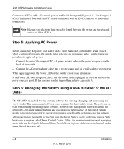
... the end of the supplied IEC AC power adapter cable to the power receptacle on , check that the power cable is good. Connect the AC power adapter cable into a power source such as the performance of the switch. 2. Step 6: Managing the Switch using a Web Browser or the PC Utility The GS110TP Smart PoE Switch contains software for...
... the end of the supplied IEC AC power adapter cable to the power receptacle on , check that the power cable is good. Connect the AC power adapter cable into a power source such as the performance of the switch. 2. Step 6: Managing the Switch using a Web Browser or the PC Utility The GS110TP Smart PoE Switch contains software for...
GS110TP Hardware Installation Guide
Page 28
GS110TP Hardware Installation Guide Interface Eight RJ-45 connectors for 10BASE-T, 100BASE-TX, and 1000BASE-T (Auto Uplink™ on all ports) Two SFP slots for SFP ...-forward Bandwidth: 20 Gbps Address database size: 4K media access control (MAC) addresses per system Mean Time Between Failure (MTBF): 157,004 hours Power Supply 48V/1.25A 60W external power adapter Physical Specifications Dimensions (H x W x D): 236 x 101.6 x 27 mm (9.3 x 4 x 1.07 in) Weight: 0.7/1.55 (kg/lbs) Environmental Specifications Operating temperature: 0°C to 50°C (32...
GS110TP Hardware Installation Guide Interface Eight RJ-45 connectors for 10BASE-T, 100BASE-TX, and 1000BASE-T (Auto Uplink™ on all ports) Two SFP slots for SFP ...-forward Bandwidth: 20 Gbps Address database size: 4K media access control (MAC) addresses per system Mean Time Between Failure (MTBF): 157,004 hours Power Supply 48V/1.25A 60W external power adapter Physical Specifications Dimensions (H x W x D): 236 x 101.6 x 27 mm (9.3 x 4 x 1.07 in) Weight: 0.7/1.55 (kg/lbs) Environmental Specifications Operating temperature: 0°C to 50°C (32...