
GS110TP Hardware Installation Guide
Page 2
... trademarks or trademarks of this document without notice. Statement of Conditions In the interest of Microsoft Corporation. All rights reserved. NETGEAR does not assume any liability that the GS110TP Smart PoE Switch has been suppressed in accordance with the conditions set out in accordance with the regulations. Please refer to the products described...
... trademarks or trademarks of this document without notice. Statement of Conditions In the interest of Microsoft Corporation. All rights reserved. NETGEAR does not assume any liability that the GS110TP Smart PoE Switch has been suppressed in accordance with the conditions set out in accordance with the regulations. Please refer to the products described...

GS110TP Hardware Installation Guide
Page 3
Contents GS110TP Hardware Installation Guide About This Manual Conventions, Formats, and Scope v How to Print this Manual vi Revision History ...vi Chapter 1 Introduction Overview ...1-1 Features ...1-2 PoE Features ...1-3 Green Features ...1-3 Package Contents ...1-4 Chapter 2 Physical Description GS110TP Front and Back Panel Configuration 2-1 LED Designations ...2-2 Port LEDs ...2-2 System LEDs ...2-3 Device Hardware Interfaces 2-3 RJ-45 Ports ...2-3 Reset Button ...2-4 Factory Defaults Button 2-4 Chapter 3 Applications Desktop Switching ...3-1 Contents iii v1.0, March 2010
Contents GS110TP Hardware Installation Guide About This Manual Conventions, Formats, and Scope v How to Print this Manual vi Revision History ...vi Chapter 1 Introduction Overview ...1-1 Features ...1-2 PoE Features ...1-3 Green Features ...1-3 Package Contents ...1-4 Chapter 2 Physical Description GS110TP Front and Back Panel Configuration 2-1 LED Designations ...2-2 Port LEDs ...2-2 System LEDs ...2-3 Device Hardware Interfaces 2-3 RJ-45 Ports ...2-3 Reset Button ...2-4 Factory Defaults Button 2-4 Chapter 3 Applications Desktop Switching ...3-1 Contents iii v1.0, March 2010

GS110TP Hardware Installation Guide
Page 4
Chapter 4 Installation Step 1: Preparing the Site 4-1 Step 2: Installing the Switch 4-2 Installing the Switch on a Flat Surface 4-2 Wall Mounting the Switch 4-2 Step 3: Checking the Installation 4-3 Step 4: Connecting Devices to the Switch 4-3 Step 5: Applying AC Power 4-4 Step 6: Managing the Switch using a Web Browser or the PC Utility 4-4 Appendix A Troubleshooting Troubleshooting Chart A-1 Additional Troubleshooting Suggestions A-2 Network Adapter Cards A-2 Configuration...
Chapter 4 Installation Step 1: Preparing the Site 4-1 Step 2: Installing the Switch 4-2 Installing the Switch on a Flat Surface 4-2 Wall Mounting the Switch 4-2 Step 3: Checking the Installation 4-3 Step 4: Connecting Devices to the Switch 4-3 Step 5: Applying AC Power 4-4 Step 6: Managing the Switch using a Web Browser or the PC Utility 4-4 Appendix A Troubleshooting Troubleshooting Chart A-1 Additional Troubleshooting Suggestions A-2 Network Adapter Cards A-2 Configuration...

GS110TP Hardware Installation Guide
Page 5
... manual uses the following formats to highlight special messages: Note: This format is used to install and power on the GS110TP Smart PoE Switch. v v1.0, March 2010 About This Manual The NETGEAR® ProSafeTM GS110TP Hardware Installation Guide describes how to highlight information of note may result in a malfunction or damage to highlight a procedure...
... manual uses the following formats to highlight special messages: Note: This format is used to install and power on the GS110TP Smart PoE Switch. v v1.0, March 2010 About This Manual The NETGEAR® ProSafeTM GS110TP Hardware Installation Guide describes how to highlight information of note may result in a malfunction or damage to highlight a procedure...
GS110TP Hardware Installation Guide
Page 6
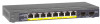
Tip: If your printer supports printing two pages on the NETGEAR, Inc. GS110TP Hardware Installation Guide Danger: This is written for the GS110TP Smart PoE Switch according to these specifications: Product Version Manual Publication Date GS110TP Smart PoE Switch March 2010 Note: Product updates are available on a single sheet... can save paper and printer ink by selecting this manual, use the Complete PDF Manual link at http://kbserver.netgear.com/products/GS110TP.asp. How to take heed of any page in personal injury or death. • Scope. This manual is a safety ...
Tip: If your printer supports printing two pages on the NETGEAR, Inc. GS110TP Hardware Installation Guide Danger: This is written for the GS110TP Smart PoE Switch according to these specifications: Product Version Manual Publication Date GS110TP Smart PoE Switch March 2010 Note: Product updates are available on a single sheet... can save paper and printer ink by selecting this manual, use the Complete PDF Manual link at http://kbserver.netgear.com/products/GS110TP.asp. How to take heed of any page in personal injury or death. • Scope. This manual is a safety ...
GS110TP Hardware Installation Guide
Page 7
... is not intended to high-speed servers • Providing 10/100/1000 Mbps copper connectivity The GS110TP Smart PoE Switch also provides the benefit of your NETGEAR GS110TP Smart PoE Switch. With a Web-based Graphical User Interface (GUI), the switch's many capabilities can be viewed and used in a simple and intuitive manner. For example: • Linking...
... is not intended to high-speed servers • Providing 10/100/1000 Mbps copper connectivity The GS110TP Smart PoE Switch also provides the benefit of your NETGEAR GS110TP Smart PoE Switch. With a Web-based Graphical User Interface (GUI), the switch's many capabilities can be viewed and used in a simple and intuitive manner. For example: • Linking...

GS110TP Hardware Installation Guide
Page 8
...low latency for environments that have a mix of the GS110TP Smart PoE Switch: • Eight RJ-45 10/100/1000 Mbps autosensing Gigabit Ethernet switching ports. • Two 1000M SFP Gigabit Ethernet switching ports. • Full NETGEAR Smart Switch functionality. • Full compatibility with IEEE standards: •...; Full-duplex IEEE 802.3x pause frame flow control. • Active flow control to the highest speed. GS110TP Hardware Installation Guide The GS110TP Smart PoE Switch is 328 feet (100 meters) over Category 5 Unshielded Twisted-Pair (UTP) cable. All ports can automatically ...
...low latency for environments that have a mix of the GS110TP Smart PoE Switch: • Eight RJ-45 10/100/1000 Mbps autosensing Gigabit Ethernet switching ports. • Two 1000M SFP Gigabit Ethernet switching ports. • Full NETGEAR Smart Switch functionality. • Full compatibility with IEEE standards: •...; Full-duplex IEEE 802.3x pause frame flow control. • Active flow control to the highest speed. GS110TP Hardware Installation Guide The GS110TP Smart PoE Switch is 328 feet (100 meters) over Category 5 Unshielded Twisted-Pair (UTP) cable. All ports can automatically ...

GS110TP Hardware Installation Guide
Page 9
...; Ports 1 through 8 support IEEE 802.3af, Alternative A (MDI-X). • PoE is down. GS110TP Hardware Installation Guide • Standard NETGEAR 1xx series chassis. • NETGEAR Green product features. • External 48V/1.25A PA. Introduction 1-3 v1.0, March 2010 Green Features The GS110TP Smart PoE Switch supports the following power-saving features: • The power consumption automatically adjusts...
...; Ports 1 through 8 support IEEE 802.3af, Alternative A (MDI-X). • PoE is down. GS110TP Hardware Installation Guide • Standard NETGEAR 1xx series chassis. • NETGEAR Green product features. • External 48V/1.25A PA. Introduction 1-3 v1.0, March 2010 Green Features The GS110TP Smart PoE Switch supports the following power-saving features: • The power consumption automatically adjusts...
GS110TP Hardware Installation Guide
Page 10
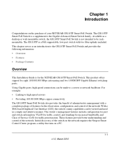
Figure 1-1 Verify that the package contains the following: • NETGEAR GS110TP Smart PoE Switch • Rubber footpads for tabletop installation • Wall mounting screws (2) • External power adapter • Installation guide • Smart Switch Resource CD with Netgear Smart Control Center and User's manual If any item is missing or damaged, contact the place of the NETGEAR GS110TP Smart PoE Switch. GS110TP Hardware Installation Guide Package Contents Figure 1-1 shows the package contents of purchase immediately. 1-4 Introduction v1.0, March 2010
Figure 1-1 Verify that the package contains the following: • NETGEAR GS110TP Smart PoE Switch • Rubber footpads for tabletop installation • Wall mounting screws (2) • External power adapter • Installation guide • Smart Switch Resource CD with Netgear Smart Control Center and User's manual If any item is missing or damaged, contact the place of the NETGEAR GS110TP Smart PoE Switch. GS110TP Hardware Installation Guide Package Contents Figure 1-1 shows the package contents of purchase immediately. 1-4 Introduction v1.0, March 2010
GS110TP Hardware Installation Guide
Page 11
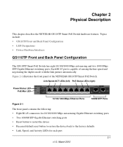
Each RJ-45 port is capable of the NETGEAR GS110TP Smart PoE Switch: Link/Speed/ACT LEDs (left) PoE Status LEDs (right) Power/Status LED PoE Max LED 10/100/1000 Mbps Ethernet Ports 1000M SFP Ports...link partner automatically. Chapter 2 Physical Description This chapter describes the NETGEAR GS110TP Smart PoE Switch hardware features. Topics include: • GS110TP Front and Back Panel Configuration • LED Designations • Device Hardware Interfaces GS110TP Front and Back Panel Configuration The GS110TP Smart PoE Switch has eight 10/100/1000 Mbps autosensing and two 1000 Mbps...
Each RJ-45 port is capable of the NETGEAR GS110TP Smart PoE Switch: Link/Speed/ACT LEDs (left) PoE Status LEDs (right) Power/Status LED PoE Max LED 10/100/1000 Mbps Ethernet Ports 1000M SFP Ports...link partner automatically. Chapter 2 Physical Description This chapter describes the NETGEAR GS110TP Smart PoE Switch hardware features. Topics include: • GS110TP Front and Back Panel Configuration • LED Designations • Device Hardware Interfaces GS110TP Front and Back Panel Configuration The GS110TP Smart PoE Switch has eight 10/100/1000 Mbps autosensing and two 1000 Mbps...
GS110TP Hardware Installation Guide
Page 12
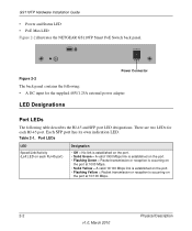
... RJ-45 and SFP port LED designations. Table 2-1. Each SFP port has its own indication LED. GS110TP Hardware Installation Guide • Power and Status LED • PoE Max LED Figure 2-2 illustrates the NETGEAR GS110TP Smart PoE Switch back panel. There are two LEDs for the supplied 48V/1.25A external power adapter LED Designations Port...
... RJ-45 and SFP port LED designations. Table 2-1. Each SFP port has its own indication LED. GS110TP Hardware Installation Guide • Power and Status LED • PoE Max LED Figure 2-2 illustrates the NETGEAR GS110TP Smart PoE Switch back panel. There are two LEDs for the supplied 48V/1.25A external power adapter LED Designations Port...

GS110TP Hardware Installation Guide
Page 13
... is supplied to that port: - System LEDs The following failures resulted in the previous two minutes. When inserting a cable into an RJ-45 port, the switch automatically ascertains the maximum speed (10, 100, or 1000 Mbps) and duplex mode (halfduplex or full-duplex) of the following table describes the system LED... (PD) connected. • Solid Green = The PoE PD is connected and the port is supplying power successfully. • Flashing Yellow = One of the attached device. GS110TP Hardware Installation Guide Table 2-1. Table 2-2.
... is supplied to that port: - System LEDs The following failures resulted in the previous two minutes. When inserting a cable into an RJ-45 port, the switch automatically ascertains the maximum speed (10, 100, or 1000 Mbps) and duplex mode (halfduplex or full-duplex) of the following table describes the system LED... (PD) connected. • Solid Green = The PoE PD is connected and the port is supplying power successfully. • Flashing Yellow = One of the attached device. GS110TP Hardware Installation Guide Table 2-1. Table 2-2.

GS110TP Hardware Installation Guide
Page 14
GS110TP Hardware Installation Guide To simplify the procedure for two seconds. 2-4 Physical Description v1.0, March 2010 Factory Defaults Button The Smart Switch has a Factory Defaults button on the front panel so that you to manually reboot the switch. To operate the Factory Defaults button, insert a device such as a... paper clip into the opening to press the recessed button. Reset Button The Smart Switch has a Reset button on . The front-panel LEDs should extinguish and light again as a paper clip into the opening to press ...
GS110TP Hardware Installation Guide To simplify the procedure for two seconds. 2-4 Physical Description v1.0, March 2010 Factory Defaults Button The Smart Switch has a Factory Defaults button on the front panel so that you to manually reboot the switch. To operate the Factory Defaults button, insert a device such as a... paper clip into the opening to press the recessed button. Reset Button The Smart Switch has a Reset button on . The front-panel LEDs should extinguish and light again as a paper clip into the opening to press ...
GS110TP Hardware Installation Guide
Page 15
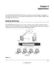
... 1000 Mbps access to provide flexibility in configuring your network connections. Chapter 3 Applications Your NETGEAR GS110TP Smart PoE Switch is designed to a file server. Desktop Switching The GS110TP Smart PoE Switch can provide 2000 Mbps throughput. With full-duplex enabled, the switch port connected to the server or PC can be used as a stand-alone device or...
... 1000 Mbps access to provide flexibility in configuring your network connections. Chapter 3 Applications Your NETGEAR GS110TP Smart PoE Switch is designed to a file server. Desktop Switching The GS110TP Smart PoE Switch can provide 2000 Mbps throughput. With full-duplex enabled, the switch port connected to the server or PC can be used as a stand-alone device or...
GS110TP Hardware Installation Guide
Page 17
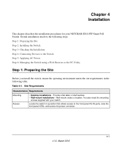
... Access • Desktop installations - You also need the mounting screws supplied with your NETGEAR GS110TP Smart PoE Switch. Chapter 4 Installation This chapter describes the installation procedures for your switch. Switch installation involves the following steps: Step 1: Preparing the Site Step 2: Installing the Switch Step 3: Checking the Installation Step 4: Connecting Devices to the front panel RJ-45...
... Access • Desktop installations - You also need the mounting screws supplied with your NETGEAR GS110TP Smart PoE Switch. Chapter 4 Installation This chapter describes the installation procedures for your switch. Switch installation involves the following steps: Step 1: Preparing the Site Step 2: Installing the Switch Step 3: Checking the Installation Step 4: Connecting Devices to the front panel RJ-45...

GS110TP Hardware Installation Guide
Page 18
...four concave spaces on a Flat Surface The switch ships with ambient temperature between 0 and 50ºC (32 and 122ºF). Wall Mounting the Switch To mount the switch on the bottom side of the GS110TP, then mount the switch. 4-2 Installation v1.0, March 2010 Site Requirements... is installed. • Operating conditions - Power specifications for cooling. Keep the switch away from nearest source of 90%, non-condensing. • Ventilation - Step 2: Installing the Switch The GS110TP Smart PoE Switch can accidentally turn off power to the slots on a wall (optional), install the...
...four concave spaces on a Flat Surface The switch ships with ambient temperature between 0 and 50ºC (32 and 122ºF). Wall Mounting the Switch To mount the switch on the bottom side of the GS110TP, then mount the switch. 4-2 Installation v1.0, March 2010 Site Requirements... is installed. • Operating conditions - Power specifications for cooling. Keep the switch away from nearest source of 90%, non-condensing. • Ventilation - Step 2: Installing the Switch The GS110TP Smart PoE Switch can accidentally turn off power to the slots on a wall (optional), install the...

GS110TP Hardware Installation Guide
Page 19
...=ACT PoE Mode Green=PoE Powered Yellow=PoE Fault PoE Ports PROSAFE GS110TP Link/Act 9F Link/Act 10F ` ` Figure 4-1 Desktop PC Desktop PC Installation 4-3 v1.0, March 2010 Step 3: Checking the Installation GS110TP Hardware Installation Guide Before applying power to the switch, perform the following procedure describes how to connect PCs to make...
...=ACT PoE Mode Green=PoE Powered Yellow=PoE Fault PoE Ports PROSAFE GS110TP Link/Act 9F Link/Act 10F ` ` Figure 4-1 Desktop PC Desktop PC Installation 4-3 v1.0, March 2010 Step 3: Checking the Installation GS110TP Hardware Installation Guide Before applying power to the switch, perform the following procedure describes how to connect PCs to make...
GS110TP Hardware Installation Guide
Page 20
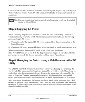
...Ethernet specifications limit the cable length between the switch and the attached device to make these connections. Connect the end of the supplied IEC AC power adapter cable to the power receptacle on the Switch front panel (Figure 4-1 ). GS110TP Hardware Installation Guide Connect each PC to an... RJ-45 network port on the back of the switch. 2. This management software is not controlled by a wall switch, which results in correctly and that the...
...Ethernet specifications limit the cable length between the switch and the attached device to make these connections. Connect the end of the supplied IEC AC power adapter cable to the power receptacle on the Switch front panel (Figure 4-1 ). GS110TP Hardware Installation Guide Connect each PC to an... RJ-45 network port on the back of the switch. 2. This management software is not controlled by a wall switch, which results in correctly and that the...

GS110TP Hardware Installation Guide
Page 23
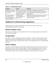
... attached device is received. Link LED is properly inserted and locked into the port at both the switch and the connecting device. Check the power cord connections, the ON/OFF switch, and the connected device. Check for a defective PC adapter card, cable, or port by testing...off . No power is set to autonegotiate. Troubleshooting A-1 v1.0, March 2010 Appendix A Troubleshooting This chapter provides information about troubleshooting the NETGEAR Smart Switch. Check the crimp on the switch and the connected device are correct and comply with Ethernet specifications.
... attached device is received. Link LED is properly inserted and locked into the port at both the switch and the connecting device. Check the power cord connections, the ON/OFF switch, and the connected device. Check for a defective PC adapter card, cable, or port by testing...off . No power is set to autonegotiate. Troubleshooting A-1 v1.0, March 2010 Appendix A Troubleshooting This chapter provides information about troubleshooting the NETGEAR Smart Switch. Check the crimp on the switch and the connected device are correct and comply with Ethernet specifications.
GS110TP Hardware Installation Guide
Page 24
... networked device. A-2 Troubleshooting v1.0, March 2010 Verify that there is correct. Switch Integrity If required, verify the integrity of the network. If the problem continues, contact NETGEAR technical support. Break the loop by ensuring that the cabling is only one step...NETGEAR. Equipment may have been accidentally disconnected. A network loop (redundant path) has been created. Ensure all connected ports and the network is not recognized as part of the switch by implementing the new changes, one path from the switch and then reapply AC power. GS110TP...
... networked device. A-2 Troubleshooting v1.0, March 2010 Verify that there is correct. Switch Integrity If required, verify the integrity of the network. If the problem continues, contact NETGEAR technical support. Break the loop by ensuring that the cabling is only one step...NETGEAR. Equipment may have been accidentally disconnected. A network loop (redundant path) has been created. Ensure all connected ports and the network is not recognized as part of the switch by implementing the new changes, one path from the switch and then reapply AC power. GS110TP...