
GS7xxTS Hardware manual
Page 5
...Revision History ...xi Chapter 1 Introduction Overview ...1-13 Switch Features ...1-15 Stacking ...1-16 Package Contents ...1-17 Chapter 2 Installation Step 1: Preparing the Site 2-29 Step 2: Installing the Switch 2-30 Installing the Switch on a Flat Surface 2-30 Installing the Switch in a Rack 2-30 Step 3: Checking the... Step 7: Applying AC Power 2-34 Step 8: Managing the Switch through a Web Browser or the PC Utility for Initial Configuration ...2-35 Chapter 3 Physical Description Front and Back Panel Configuration 3-19 GS724TS Front and Back Panels 3-19 GS748TS Front and Back Panels ...
...Revision History ...xi Chapter 1 Introduction Overview ...1-13 Switch Features ...1-15 Stacking ...1-16 Package Contents ...1-17 Chapter 2 Installation Step 1: Preparing the Site 2-29 Step 2: Installing the Switch 2-30 Installing the Switch on a Flat Surface 2-30 Installing the Switch in a Rack 2-30 Step 3: Checking the... Step 7: Applying AC Power 2-34 Step 8: Managing the Switch through a Web Browser or the PC Utility for Initial Configuration ...2-35 Chapter 3 Physical Description Front and Back Panel Configuration 3-19 GS724TS Front and Back Panels 3-19 GS748TS Front and Back Panels ...

GS7xxTS Hardware manual
Page 10
...NETGEAR Smart Switch is for the following NETGEAR Smart Switches: • GS724TS - This product offers support for a maximunm of 192 10/100 ports or you can make high-speed connections using the Gigabit ports. To simplify installation, the switch is shipped ready for use a device as an introduction to six units for 24 ports... require a large number of ports and want the power of the box. This chapter serves as a stand-alone. You can stack together up to the GS700TS Smart Switch and provides the following information: • Overview • Switch Features • Package Contents ...
...NETGEAR Smart Switch is for the following NETGEAR Smart Switches: • GS724TS - This product offers support for a maximunm of 192 10/100 ports or you can make high-speed connections using the Gigabit ports. To simplify installation, the switch is shipped ready for use a device as an introduction to six units for 24 ports... require a large number of ports and want the power of the box. This chapter serves as a stand-alone. You can stack together up to the GS700TS Smart Switch and provides the following information: • Overview • Switch Features • Package Contents ...

GS7xxTS Hardware manual
Page 13
... Installation Guide • The devices support full Netgear Smart Switch functionality and provide full compatibility with the following : • Web-based Interface • SNMP Management Station Devices support stacking up to build the packet-forwarding information table. The stack can operate as if all 10/100/1000 Mbps ports. • Store-and-Forward transmission to remove...
... Installation Guide • The devices support full Netgear Smart Switch functionality and provide full compatibility with the following : • Web-based Interface • SNMP Management Station Devices support stacking up to build the packet-forwarding information table. The stack can operate as if all 10/100/1000 Mbps ports. • Store-and-Forward transmission to remove...

GS7xxTS Hardware manual
Page 14
... running the same software version. The backup master acts as a single interface in the stack must be selected manually. The master and backup master are named as a general switch and does not run the stacking application. • Master Unit - A device can become a Master-Backup. •... will need to be running on the master unit to control and manage the stack. GS700TS Hardware Installation Guide During the Stacking setup, the switches will auto-select one of the following modes: • Stand-alone - One of the NETGEAR Smart Switch 1-17 v1.0, November 2007 Introduction
... running the same software version. The backup master acts as a single interface in the stack must be selected manually. The master and backup master are named as a general switch and does not run the stacking application. • Master Unit - A device can become a Master-Backup. •... will need to be running on the master unit to control and manage the stack. GS700TS Hardware Installation Guide During the Stacking setup, the switches will auto-select one of the following modes: • Stand-alone - One of the NETGEAR Smart Switch 1-17 v1.0, November 2007 Introduction

GS7xxTS Hardware manual
Page 20
Press firmly to ensure the module seats into the connector Figure 2-3 Step 6: Installing a Device The device can operate as part of the device are two stacking topologies supported by the device, the Ring topology or Chain topology. 2-33 v1.0, November 2007 Installation There are used for connecting the devices in a stack. The HX stacking ports on the back of a stack. GS700TS Hardware Installation Guide 2.
Press firmly to ensure the module seats into the connector Figure 2-3 Step 6: Installing a Device The device can operate as part of the device are two stacking topologies supported by the device, the Ring topology or Chain topology. 2-33 v1.0, November 2007 Installation There are used for connecting the devices in a stack. The HX stacking ports on the back of a stack. GS700TS Hardware Installation Guide 2.

GS7xxTS Hardware manual
Page 21
... or removing AC power is not controlled by connecting or disconnecting the power cord. Step 7: Applying AC Power NETGEAR Smart Switch does not have an ON/OFF switch. When applying power, the Power LED on stacking see the NETGEAR Smart Switch User Guide. GS700TS Hardware Installation Guide Figure 2-4 The device is operational. Installation v1.0, November 2007 2-34 Before...
... or removing AC power is not controlled by connecting or disconnecting the power cord. Step 7: Applying AC Power NETGEAR Smart Switch does not have an ON/OFF switch. When applying power, the Power LED on stacking see the NETGEAR Smart Switch User Guide. GS700TS Hardware Installation Guide Figure 2-4 The device is operational. Installation v1.0, November 2007 2-34 Before...

GS7xxTS Hardware manual
Page 24
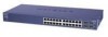
... + 4-Port SFP Combo port smart stackable switch, with each RJ45 ports capable of sensing the line speed and negotiating the operation duplex mode with the link partner automatically. GS700TS Hardware Installation Guide Figure 3-2 illustrates the NETGEAR GS724TS Smart Switch back panel: Figure 3-2 The back panel contains the following : • 48 RJ-45 connectors for 10Base-T, 100Base-T and 1000Base-T. • Four Gigabit...
... + 4-Port SFP Combo port smart stackable switch, with each RJ45 ports capable of sensing the line speed and negotiating the operation duplex mode with the link partner automatically. GS700TS Hardware Installation Guide Figure 3-2 illustrates the NETGEAR GS724TS Smart Switch back panel: Figure 3-2 The back panel contains the following : • 48 RJ-45 connectors for 10Base-T, 100Base-T and 1000Base-T. • Four Gigabit...

GS7xxTS Hardware manual
Page 25
GS700TS Hardware Installation Guide Figure 3-2 illustrates the NETGEAR GS748TS Smart Switch back panel: Figure 3-4 The back panel contains the following LED types: • Port LEDs • System LEDs Physical Description v1.0, November 2007 3-21 LED Designations This section provides an explanation for the following : • A 100-240VAC/50-60 Hz universal input, which is a standard AC power receptacle for accommodating the supplied power cord. • Two 19 pin HX stacking ports for full-duplex stacking linking.
GS700TS Hardware Installation Guide Figure 3-2 illustrates the NETGEAR GS748TS Smart Switch back panel: Figure 3-4 The back panel contains the following LED types: • Port LEDs • System LEDs Physical Description v1.0, November 2007 3-21 LED Designations This section provides an explanation for the following : • A 100-240VAC/50-60 Hz universal input, which is a standard AC power receptacle for accommodating the supplied power cord. • Two 19 pin HX stacking ports for full-duplex stacking linking.

GS7xxTS Hardware manual
Page 26
... Yellow - A valid 100Mbps link is in a stack of switches. • Solid Green - A valid 10Mbps link is established on the port. • Flashing Yellow - Port LEDs Port LED 24/48-10/100/1000 Ports Link/ACT LED - System LEDs The following table describes the port LED designations. No link is established on the port. • Solid Green - One LED/ SFP...
... Yellow - A valid 100Mbps link is in a stack of switches. • Solid Green - A valid 10Mbps link is established on the port. • Flashing Yellow - Port LEDs Port LED 24/48-10/100/1000 Ports Link/ACT LED - System LEDs The following table describes the port LED designations. No link is established on the port. • Solid Green - One LED/ SFP...

GS7xxTS Hardware manual
Page 27
... or reception is down. • Solid Green - Power is supplied to a router, switch, or hub). When inserting a cable into the switch's RJ-45 port, the switch automatically: • Senses whether the cable is operating normally. • Solid Green - Indicates the Down stacking port link is disconnected. • Solid Green - Device Hardware Interfaces This section provides information...
... or reception is down. • Solid Green - Power is supplied to a router, switch, or hub). When inserting a cable into the switch's RJ-45 port, the switch automatically: • Senses whether the cable is operating normally. • Solid Green - Indicates the Down stacking port link is disconnected. • Solid Green - Device Hardware Interfaces This section provides information...

GS7xxTS Hardware manual
Page 32
LEDs Per port (Gigabit): Link/Activity, Speed, Stack (for SFP module. Four Small Form-factor Pluggable (SFP) slots for stacking-enabled ports) Per device: Power, Stack Master, Unit Number B-1 v1.0, November 2007 Appendix B Technical Specifications Network Protocol and Standards Compatibility IEEE 802.3i 10Base... from 2 to 4K) IEEE 802.1p Class of Service (CoS) Port-based QoS (options High/Normal) Port Trunking LACP Interface 24/48 RJ-45 connectors for 10Base-T,100Base-TX and 1000Base-(Auto Uplink™ on all ports). 4 RJ-45 connectors for 10Base-T ,100Base-TX and 1000Base-T, shared...
LEDs Per port (Gigabit): Link/Activity, Speed, Stack (for SFP module. Four Small Form-factor Pluggable (SFP) slots for stacking-enabled ports) Per device: Power, Stack Master, Unit Number B-1 v1.0, November 2007 Appendix B Technical Specifications Network Protocol and Standards Compatibility IEEE 802.3i 10Base... from 2 to 4K) IEEE 802.1p Class of Service (CoS) Port-based QoS (options High/Normal) Port Trunking LACP Interface 24/48 RJ-45 connectors for 10Base-T,100Base-TX and 1000Base-(Auto Uplink™ on all ports). 4 RJ-45 connectors for 10Base-T ,100Base-TX and 1000Base-T, shared...

GS7xxTS Hardware manual
Page 33
...-forward Bandwidth: 68 Gbps (for GS724TS) / 116 Gbps (for GS748TS) Stacking Port Bandwidth: 20 Gbps Address database size: 4K media access control (MAC) addresses per system Mean Time Between Failure (MTBF): 167,355 hours for GS724TS, 125,566 hours for GS748TS Power Supply Power Consumption: 35.1W for GS724TS, 78.36W for GS748TS 100-240VAC...
...-forward Bandwidth: 68 Gbps (for GS724TS) / 116 Gbps (for GS748TS) Stacking Port Bandwidth: 20 Gbps Address database size: 4K media access control (MAC) addresses per system Mean Time Between Failure (MTBF): 167,355 hours for GS724TS, 125,566 hours for GS748TS Power Supply Power Consumption: 35.1W for GS724TS, 78.36W for GS748TS 100-240VAC...

GS7xxTS User Manual
Page 6
GS700TS Smart Switch Software Administration Manual Chapter 3 Managing System Settings Using the System Settings Utility 3-1 Management ...3-1 System Information 3-1 IP Configuration ...3-4 Time ...3-5 Device View ...3-8 Stacking ...3-8 Operation Modes ...3-9 Understanding Stack Topology 3-9 Stacking Ports ...3-10 Stacking Members and Unit No 3-10 Removing and Replacing Stacking Members 3-11 Inserting a Stacking Member 3-12 Exchanging Stacking Members 3-12 Switching the Stacking Master 3-13 Stack Configuration and Management 3-13 SNMP ...3-17...
GS700TS Smart Switch Software Administration Manual Chapter 3 Managing System Settings Using the System Settings Utility 3-1 Management ...3-1 System Information 3-1 IP Configuration ...3-4 Time ...3-5 Device View ...3-8 Stacking ...3-8 Operation Modes ...3-9 Understanding Stack Topology 3-9 Stacking Ports ...3-10 Stacking Members and Unit No 3-10 Removing and Replacing Stacking Members 3-11 Inserting a Stacking Member 3-12 Exchanging Stacking Members 3-12 Switching the Stacking Master 3-13 Stack Configuration and Management 3-13 SNMP ...3-17...

GS7xxTS User Manual
Page 23
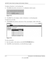
... upgrading in the form: • Product Assigned Firmware: The location of the new firmware. Getting Started with Switch Management v1.0, June 2009 1-10 GS700TS Smart Switch Software Administration Manual Figure 1-6 1. If you do not know the location, click Browse to begin loading the ...is complete, the switch automatically reboots. Exit Click Exit from the SmartWizard Discovery screen to the Upgrade Configuration. 3. Click Apply to apply the settings to close the SmartWizard Discovery utility. The system software is automatically loaded to all stacking members. Enter the ...
... upgrading in the form: • Product Assigned Firmware: The location of the new firmware. Getting Started with Switch Management v1.0, June 2009 1-10 GS700TS Smart Switch Software Administration Manual Figure 1-6 1. If you do not know the location, click Browse to begin loading the ...is complete, the switch automatically reboots. Exit Click Exit from the SmartWizard Discovery screen to the Upgrade Configuration. 3. Click Apply to apply the settings to close the SmartWizard Discovery utility. The system software is automatically loaded to all stacking members. Enter the ...

GS7xxTS User Manual
Page 32
GS700TS Smart Switch Software Administration Manual Quick Boxes Quick Boxes provide users with flexibility in configuring VLANs for Unit 1, marking the ports as Tagged. Click on the Unit 1 quick box, and a U appears in the quick box and in the quick box. Click again on the ...Clicking on the Unit 1 gold button to the right of the arrow on a stacking unit level) or LAGs. A T appears in all the port boxes f for all Tagged. A quick box appears to display the Unit 1 ports, which are now all ports (on the left of the gold button. The following example displays quick box ...
GS700TS Smart Switch Software Administration Manual Quick Boxes Quick Boxes provide users with flexibility in configuring VLANs for Unit 1, marking the ports as Tagged. Click on the Unit 1 quick box, and a U appears in the quick box and in the quick box. Click again on the ...Clicking on the Unit 1 gold button to the right of the arrow on a stacking unit level) or LAGs. A T appears in all the port boxes f for all Tagged. A quick box appears to display the Unit 1 ports, which are now all ports (on the left of the gold button. The following example displays quick box ...

GS7xxTS User Manual
Page 33
... row, located above the row of all ports in the interface selection row. GS700TS Smart Switch Software Administration Manual Figure 2-13 4. The screen displays a table of column headers. Clicking on individual port boxes to the Web Browser Interface v1.0, June 2009 2-10 Click the unit number in a stacking unit: 1. Click again on the Unit 1 quick...
... row, located above the row of all ports in the interface selection row. GS700TS Smart Switch Software Administration Manual Figure 2-13 4. The screen displays a table of column headers. Clicking on individual port boxes to the Web Browser Interface v1.0, June 2009 2-10 Click the unit number in a stacking unit: 1. Click again on the Unit 1 quick...
GS7xxTS User Manual
Page 34
... displays a table of the interface in all LAGs. Click OK. Click GO to select the interface, as in all stacking units: 1. GS700TS Smart Switch Software Administration Manual To display all interfaces in the following example. 2-11 Introduction to the Web Browser Interface v1.0, June ...2009 Figure 2-16 To select an interface: 1. Figure 2-15 2. Enter the number of all stacking units. Click All in the interface ...
... displays a table of the interface in all LAGs. Click OK. Click GO to select the interface, as in all stacking units: 1. GS700TS Smart Switch Software Administration Manual To display all interfaces in the following example. 2-11 Introduction to the Web Browser Interface v1.0, June ...2009 Figure 2-16 To select an interface: 1. Figure 2-15 2. Enter the number of all stacking units. Click All in the interface ...

GS7xxTS User Manual
Page 36
... browser interface contains a System tab that follows in this chapter describes configuring and managing system settings in the GS700TS Smart Switch. Chapter 3 Managing System Settings Using the System Settings Utility The navigation pane at the top of general device information... Information screen displays basic device information and allows network managers to manage your GS700TS Smart Switch displaying configurable features under the following main menu options: • "Management" • "Device View" • "Stacking" • "SNMP" • "LLDP" The description that enables you to...
... browser interface contains a System tab that follows in this chapter describes configuring and managing system settings in the GS700TS Smart Switch. Chapter 3 Managing System Settings Using the System Settings Utility The navigation pane at the top of general device information... Information screen displays basic device information and allows network managers to manage your GS700TS Smart Switch displaying configurable features under the following main menu options: • "Management" • "Device View" • "Stacking" • "SNMP" • "LLDP" The description that enables you to...

GS7xxTS User Manual
Page 38
... the device is the default value. The possible field values are 1-6. • Model Name - This is currently in standalone or stacking mode. • Change Unit Mode To... Displays the installed device hardware version number. • Boot Version - Toggle the device unit... are timed out must reset the device for detailed instructions on the device. • Software Version - Enables Jumbo Frames. - Displays the stacking member's current number. Displays the device model name. • Hardware Version - The field default value is 5 30 minutes. Displays the Jumbo...
... the device is the default value. The possible field values are 1-6. • Model Name - This is currently in standalone or stacking mode. • Change Unit Mode To... Displays the installed device hardware version number. • Boot Version - Toggle the device unit... are timed out must reset the device for detailed instructions on the device. • Software Version - Enables Jumbo Frames. - Displays the stacking member's current number. Displays the device model name. • Hardware Version - The field default value is 5 30 minutes. Displays the Jumbo...

GS7xxTS User Manual
Page 43
... accessed through a single IP address through which provides a graphic representation of the stack members. The device software is downloaded separately for each of the device, including the port and LED statuses. To display the Device View screen: 1. GS700TS Smart Switch Software Administration Manual Device View The Device View menu displays the Device View screen...
... accessed through a single IP address through which provides a graphic representation of the stack members. The device software is downloaded separately for each of the device, including the port and LED statuses. To display the Device View screen: 1. GS700TS Smart Switch Software Administration Manual Device View The Device View menu displays the Device View screen...