
GS716Tv2/GS724Tv3 Hardware manual
Page 2
... not assume any liability that the Smart Switch has been suppressed in accordance with the conditions set out in accordance with the regulations. © 2007, 2008, 2009 by NETGEAR, Inc. Please refer to the use or application of their respective holders. The Federal Office for Telecommunications Approvals has been notified of the...
... not assume any liability that the Smart Switch has been suppressed in accordance with the conditions set out in accordance with the regulations. © 2007, 2008, 2009 by NETGEAR, Inc. Please refer to the use or application of their respective holders. The Federal Office for Telecommunications Approvals has been notified of the...

GS716Tv2/GS724Tv3 Hardware manual
Page 3
... Panel Configuration 2-6 LED Designations ...2-7 Port LEDs ...2-7 System LEDs ...2-8 Device Hardware Interfaces 2-8 RJ-45 Ports ...2-8 SFP GBIC Module ...2-9 Factory Defaults Button 2-9 Chapter 3 Applications Desktop Switching ...3-11 Chapter 4 Installation Step 1: Preparing the Site 4-13 Step 2: Installing the Switch 4-14 Installing the Switch on a Flat Surface 4-14 Installing the Switch in a Rack 4-14 iii v1.0, June 2009
... Panel Configuration 2-6 LED Designations ...2-7 Port LEDs ...2-7 System LEDs ...2-8 Device Hardware Interfaces 2-8 RJ-45 Ports ...2-8 SFP GBIC Module ...2-9 Factory Defaults Button 2-9 Chapter 3 Applications Desktop Switching ...3-11 Chapter 4 Installation Step 1: Preparing the Site 4-13 Step 2: Installing the Switch 4-14 Installing the Switch on a Flat Surface 4-14 Installing the Switch in a Rack 4-14 iii v1.0, June 2009

GS716Tv2/GS724Tv3 Hardware manual
Page 4
GS716T/GS724T Hardware Installation Guide Step 3: Checking the Installation 4-15 Step 4: Connecting Devices to the Switch 4-16 Step 5: Installing an SFP GBIC Module 4-16 Step 6: Applying AC Power 4-17 Step 7: Managing the Switch using a Web Browser or the PC Utility 4-18 Appendix A Troubleshooting Troubleshooting Chart A-19 Additional Troubleshooting Suggestions A-20 Network Adapter Cards A-20 Configuration ...A-20 Switch Integrity ...A-20 Auto-Negotiation A-21 Appendix B Technical Specifications Index iv v1.0, June 2009
GS716T/GS724T Hardware Installation Guide Step 3: Checking the Installation 4-15 Step 4: Connecting Devices to the Switch 4-16 Step 5: Installing an SFP GBIC Module 4-16 Step 6: Applying AC Power 4-17 Step 7: Managing the Switch using a Web Browser or the PC Utility 4-18 Appendix A Troubleshooting Troubleshooting Chart A-19 Additional Troubleshooting Suggestions A-20 Network Adapter Cards A-20 Configuration ...A-20 Switch Integrity ...A-20 Auto-Negotiation A-21 Appendix B Technical Specifications Index iv v1.0, June 2009

GS716Tv2/GS724Tv3 Hardware manual
Page 5
About This Manual The NETGEAR® ProSafeTM GS716T/GS724T Hardware Installation Guide describes how to highlight information of this manual are described in a malfunction or damage to highlight a procedure that ... conventions, formats, and scope of importance or special interest. v v1.0, June 2009 Warning: Ignoring this manual is used to install, configure and troubleshoot the Smart Switch.
About This Manual The NETGEAR® ProSafeTM GS716T/GS724T Hardware Installation Guide describes how to highlight information of this manual are described in a malfunction or damage to highlight a procedure that ... conventions, formats, and scope of importance or special interest. v v1.0, June 2009 Warning: Ignoring this manual is used to install, configure and troubleshoot the Smart Switch.

GS716Tv2/GS724Tv3 Hardware manual
Page 6
Revision History Part Number Version Number Date 202-10510-01 1.0 June 2009 Description Initial release vi v1.0, June 2009 Failure to these specifications: Product Version Manual Publication Date Smart Switch June 2009 Note: Product updates are available on the NETGEAR, Inc. This manual is a safety warning. website at http://kbserver.netgear.com/main.asp. GS716T/GS724T Hardware Installation Guide Danger: This is written for the Smart Switch according to take heed of this notice may result in personal injury or death. • Scope.
Revision History Part Number Version Number Date 202-10510-01 1.0 June 2009 Description Initial release vi v1.0, June 2009 Failure to these specifications: Product Version Manual Publication Date Smart Switch June 2009 Note: Product updates are available on the NETGEAR, Inc. This manual is a safety warning. website at http://kbserver.netgear.com/main.asp. GS716T/GS724T Hardware Installation Guide Danger: This is written for the Smart Switch according to take heed of this notice may result in personal injury or death. • Scope.

GS716Tv2/GS724Tv3 Hardware manual
Page 7
...Gigabit ports, high-speed connections can be made to the Smart Switch and provides the following information: • Overview • Features • Package Contents Overview This Installation Guide is shipped ready for 24 ports of the box. To simplify installation, the switch is for increased bandwidth, and Class of the NETGEAR Smart Switch. The switch's management... features include configuration for port and switch information, VLAN for traffic control...
...Gigabit ports, high-speed connections can be made to the Smart Switch and provides the following information: • Overview • Features • Package Contents Overview This Installation Guide is shipped ready for 24 ports of the box. To simplify installation, the switch is for increased bandwidth, and Class of the NETGEAR Smart Switch. The switch's management... features include configuration for port and switch information, VLAN for traffic control...

GS716Tv2/GS724Tv3 Hardware manual
Page 8
...negotiate to the Combo ports are supported: • 1000BASE-SX • 1000BASE-LX • 100BASE-FX • The devices support full NETGEAR Smart Switch functionality. • The devices provide full compatibility with IEEE standards: • IEEE 802.3i, (10BASE-T) • IEEE 802.3u (..., SFP fiber and RJ-45 copper. These features provide better understanding and control of Ethernet, Fast Ethernet, or Gigabit Ethernet devices. This capability makes the switch ideal for high-speed networking. GS716T/GS724T Hardware Installation Guide Service (CoS) for all ports. • Auto ...
...negotiate to the Combo ports are supported: • 1000BASE-SX • 1000BASE-LX • 100BASE-FX • The devices support full NETGEAR Smart Switch functionality. • The devices provide full compatibility with IEEE standards: • IEEE 802.3i, (10BASE-T) • IEEE 802.3u (..., SFP fiber and RJ-45 copper. These features provide better understanding and control of Ethernet, Fast Ethernet, or Gigabit Ethernet devices. This capability makes the switch ideal for high-speed networking. GS716T/GS724T Hardware Installation Guide Service (CoS) for all ports. • Auto ...

GS716Tv2/GS724Tv3 Hardware manual
Page 9
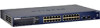
Package Contents Figure 1-1 shows the package contents of the NETGEAR GS716T and GS724T Series Smart Switch. Reset PWR ® ProSafe 24 Port Gigabit Smart Switch 1 3 5 7 9 11 13 15 17 19 21 23 LINK/ACT SPD Green (1000M) Yellow (100M) FDX 2 4 6 8 10 12 14 16 18 20 22 24 LINK/ACT ...
Package Contents Figure 1-1 shows the package contents of the NETGEAR GS716T and GS724T Series Smart Switch. Reset PWR ® ProSafe 24 Port Gigabit Smart Switch 1 3 5 7 9 11 13 15 17 19 21 23 LINK/ACT SPD Green (1000M) Yellow (100M) FDX 2 4 6 8 10 12 14 16 18 20 22 24 LINK/ACT ...

GS716Tv2/GS724Tv3 Hardware manual
Page 10
GS716T/GS724T Hardware Installation Guide Verify that the package contains the following: • NETGEAR Smart Switch • Rubber footpads for tabletop installation • Power cord • Rack-mount kit for installing the switch in a 19-inch rack • Installation guide • Smart Switch Resource CD with Smart Wizard Discovery and User's manual • Warranty/Support Information Card If any item is missing or damaged, contact the place of purchase immediately. 1-4 Introduction v1.0, June 2009
GS716T/GS724T Hardware Installation Guide Verify that the package contains the following: • NETGEAR Smart Switch • Rubber footpads for tabletop installation • Power cord • Rack-mount kit for installing the switch in a 19-inch rack • Installation guide • Smart Switch Resource CD with Smart Wizard Discovery and User's manual • Warranty/Support Information Card If any item is missing or damaged, contact the place of purchase immediately. 1-4 Introduction v1.0, June 2009
GS716Tv2/GS724Tv3 Hardware manual
Page 11
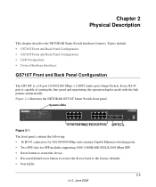
... of sensing the line speed and negotiating the operation duplex mode with the link partner automatically Figure 2-1 illustrates the NETGEAR GS716T Smart Switch front panel: System LEDs Reset PWR ® ProSafe 16 Port Gigabit Smart Switch 1 3 5 7 9 11 13 15 LINK/ACT SPD Green (1000M) Yellow (100M) FDX 2 4 6 8 10 ...Mbps Ethernet Ports SFP Ports The front panel contains the following: • 16 RJ-45 connectors for 10/100/1000 Mbps auto sensing Gigabit Ethernet switching ports. • Two SFP slots for SFP modules supporting 1000 (1000BASE-SX/LX)/100 Mbps SFP. • Reset button to restart...
... of sensing the line speed and negotiating the operation duplex mode with the link partner automatically Figure 2-1 illustrates the NETGEAR GS716T Smart Switch front panel: System LEDs Reset PWR ® ProSafe 16 Port Gigabit Smart Switch 1 3 5 7 9 11 13 15 LINK/ACT SPD Green (1000M) Yellow (100M) FDX 2 4 6 8 10 ...Mbps Ethernet Ports SFP Ports The front panel contains the following: • 16 RJ-45 connectors for 10/100/1000 Mbps auto sensing Gigabit Ethernet switching ports. • Two SFP slots for SFP modules supporting 1000 (1000BASE-SX/LX)/100 Mbps SFP. • Reset button to restart...

GS716Tv2/GS724Tv3 Hardware manual
Page 12
... factory defaults. 2-6 Physical Description v1.0, June 2009 GS716T/GS724T Hardware Installation Guide • System LEDs Figure 2-2 illustrates the NETGEAR GS716T Smart Switch back panel: 100-240V ~ 50-60Hz Figure 2-2 RS-232 Power Connector The back panel contains the following : •... sensing the line speed and negotiating the operation duplex mode with the link partner automatically Figure 2-3 illustrates the NETGEAR GS724T Smart Switch front panel: System LEDs Reset PWR ® ProSafe 24 Port Gigabit Smart Switch 1 3 5 7 9 11 13 15 17 19 21 23 LINK/ACT SPD Green (1000M) Yellow ...
... factory defaults. 2-6 Physical Description v1.0, June 2009 GS716T/GS724T Hardware Installation Guide • System LEDs Figure 2-2 illustrates the NETGEAR GS716T Smart Switch back panel: 100-240V ~ 50-60Hz Figure 2-2 RS-232 Power Connector The back panel contains the following : •... sensing the line speed and negotiating the operation duplex mode with the link partner automatically Figure 2-3 illustrates the NETGEAR GS724T Smart Switch front panel: System LEDs Reset PWR ® ProSafe 24 Port Gigabit Smart Switch 1 3 5 7 9 11 13 15 17 19 21 23 LINK/ACT SPD Green (1000M) Yellow ...

GS716Tv2/GS724Tv3 Hardware manual
Page 13
... Ports - 3 LEDs per port LED LINK/ACT SPD FDX Designation • Solid Green - GS716T/GS724T Hardware Installation Guide • System LEDs Figure 2-4 illustrates the NETGEAR GS724T Smart Switch back panel: Figure 2-4 100-240V ~ 50-60Hz RS-232 Power Connector The back panel contains the following table describes the port LED designations. LED...
... Ports - 3 LEDs per port LED LINK/ACT SPD FDX Designation • Solid Green - GS716T/GS724T Hardware Installation Guide • System LEDs Figure 2-4 illustrates the NETGEAR GS724T Smart Switch back panel: Figure 2-4 100-240V ~ 50-60Hz RS-232 Power Connector The back panel contains the following table describes the port LED designations. LED...

GS716Tv2/GS724Tv3 Hardware manual
Page 14
...through or crossover cables. System LEDs The following table describes the system LED designations. Table 2-2. When inserting a cable into an RJ-45 port, the switch automatically ascertains the maximum speed (10, 100, or 1000 Mbps) and duplex mode (halfduplex or full-duplex) of the attached device. A valid ... Solid Green - Power is supplied to the RJ-45 ports with an 8-pin RJ-45 plug. When inserting a cable into the switch's RJ-45 port, the switch automatically: • Senses whether the cable is occurring on the port at 1000 Mbps. • Solid Yellow - This technology allows ...
...through or crossover cables. System LEDs The following table describes the system LED designations. Table 2-2. When inserting a cable into an RJ-45 port, the switch automatically ascertains the maximum speed (10, 100, or 1000 Mbps) and duplex mode (halfduplex or full-duplex) of the attached device. A valid ... Solid Green - Power is supplied to the RJ-45 ports with an 8-pin RJ-45 plug. When inserting a cable into the switch's RJ-45 port, the switch automatically: • Senses whether the cable is occurring on the port at 1000 Mbps. • Solid Yellow - This technology allows ...

GS716Tv2/GS724Tv3 Hardware manual
Page 15
...normal" connection (such as when connecting the port to a PC) or an "uplink" connection (such as the AGM731F, AGM732F, or AGM733 from NETGEAR, allowing fiber connections on the network. Being a combo port, only one type of connection can remove the current configuration and return the device to ...use crossover or straightthrough cables when attaching devices. When you can be used at any given time. Factory Defaults Button The Smart Switch has a Factory Default button so that you enable the Factory Default button, all settings, including the password, VLAN settings and port ...
...normal" connection (such as when connecting the port to a PC) or an "uplink" connection (such as the AGM731F, AGM732F, or AGM733 from NETGEAR, allowing fiber connections on the network. Being a combo port, only one type of connection can remove the current configuration and return the device to ...use crossover or straightthrough cables when attaching devices. When you can be used at any given time. Factory Defaults Button The Smart Switch has a Factory Default button so that you enable the Factory Default button, all settings, including the password, VLAN settings and port ...

GS716Tv2/GS724Tv3 Hardware manual
Page 16
Desktop Switching The NETGEAR Smart Switch can be used as a stand-alone device or with 10 Mbps, 100 Mbps, and 1000 Mbps hubs and switches. With full-duplex enabled, the switch port connected to the server or PC can be used as a desktop switch to build a small network that enables users to have 1000 Mbps access to provide flexibility in configuring your network connections. It can provide 2000 Mbps throughput. Chapter 3 Applications Your NETGEAR Smart Switch is designed to a file server. Figure 3-1 v1.0, June 2009 3-11
Desktop Switching The NETGEAR Smart Switch can be used as a stand-alone device or with 10 Mbps, 100 Mbps, and 1000 Mbps hubs and switches. With full-duplex enabled, the switch port connected to the server or PC can be used as a desktop switch to build a small network that enables users to have 1000 Mbps access to provide flexibility in configuring your network connections. It can provide 2000 Mbps throughput. Chapter 3 Applications Your NETGEAR Smart Switch is designed to a file server. Figure 3-1 v1.0, June 2009 3-11

GS716Tv2/GS724Tv3 Hardware manual
Page 17
...NETGEAR Smart Switch. v1.0, June 2009 4-13 Table 4-1. Provide a flat table or shelf surface. • Rack-mount installations - Site Requirements Characteristics Requirements Mounting Access • Desktop installations - Switch installation involves the following steps: Step 1: Preparing the Site Step 2: Installing the Switch...that allows access to the Switch Step 5: Installing an SFP GBIC Module Step 6: Applying AC Power Step 7: Managing the Switch using a Web Browser or the PC Utility Step 1: Preparing the Site Before you installing the switch, ensure the operating environment ...
...NETGEAR Smart Switch. v1.0, June 2009 4-13 Table 4-1. Provide a flat table or shelf surface. • Rack-mount installations - Site Requirements Characteristics Requirements Mounting Access • Desktop installations - Switch installation involves the following steps: Step 1: Preparing the Site Step 2: Installing the Switch...that allows access to the Switch Step 5: Installing an SFP GBIC Module Step 6: Applying AC Power Step 7: Managing the Switch using a Web Browser or the PC Utility Step 1: Preparing the Site Before you installing the switch, ensure the operating environment ...

GS716Tv2/GS724Tv3 Hardware manual
Page 18
.... 4-14 v1.0, June 2009 Installation Align the mounting holes in the brackets with the holes in the switch. 3. Step 2: Installing the Switch The NETGEAR Smart Switch can accidentally turn off power to Figure 4-1). The rubber footpads cushion the switch against shock/vibrations. To perform this procedure, the 17-inch rack-mount kit supplied with nylon...
.... 4-14 v1.0, June 2009 Installation Align the mounting holes in the brackets with the holes in the switch. 3. Step 2: Installing the Switch The NETGEAR Smart Switch can accidentally turn off power to Figure 4-1). The rubber footpads cushion the switch against shock/vibrations. To perform this procedure, the 17-inch rack-mount kit supplied with nylon...

GS716Tv2/GS724Tv3 Hardware manual
Page 19
Installation v1.0, June 2009 4-15 Tighten the screws with a #2 Phillips screwdriver to make sure cables are not damaged or creating a safety hazard. • Ensure all cables are installed correctly. • Check cable routing to secure the switch in the rack. GS716T/GS724T Hardware Installation Guide 5. Figure 4-1 Step 3: Checking the Installation Before applying power perform the following: • Inspect the equipment thoroughly. • Verify that all equipment is mounted properly and securely.
Installation v1.0, June 2009 4-15 Tighten the screws with a #2 Phillips screwdriver to make sure cables are not damaged or creating a safety hazard. • Ensure all cables are installed correctly. • Check cable routing to secure the switch in the rack. GS716T/GS724T Hardware Installation Guide 5. Figure 4-1 Step 3: Checking the Installation Before applying power perform the following: • Inspect the equipment thoroughly. • Verify that all equipment is mounted properly and securely.

GS716Tv2/GS724Tv3 Hardware manual
Page 20
The NETGEAR Smart Switch contains Auto Uplink™ technology, which allows the attaching of devices using either straight-through or crossover cables. Use Category 5 (Cat5) Unshielded Twisted-Pair (UTP) ... at this time, skip this procedure. Note: Ethernet specifications limit the cable length between the switch and the attached device to make these connections. Figure 4-2 Connect each PC to install an SFP Gigabit Ethernet module in the switch's Gigabit module bay. Step 5: Installing an SFP GBIC Module The following procedure describes how to connect...
The NETGEAR Smart Switch contains Auto Uplink™ technology, which allows the attaching of devices using either straight-through or crossover cables. Use Category 5 (Cat5) Unshielded Twisted-Pair (UTP) ... at this time, skip this procedure. Note: Ethernet specifications limit the cable length between the switch and the attached device to make these connections. Figure 4-2 Connect each PC to install an SFP Gigabit Ethernet module in the switch's Gigabit module bay. Step 5: Installing an SFP GBIC Module The following procedure describes how to connect...

GS716Tv2/GS724Tv3 Hardware manual
Page 21
Figure 4-3 Step 6: Applying AC Power NETGEAR Smart Switch does not have an ON/OFF switch. Connect the 3-pronged end of the switch. 2. Before connecting the power cord, select an AC outlet that the power source is by a wall switch, which can turn off power to the power receptacle on , check that... the power cable is plugged in correctly and that is Green. The method of the supplied AC power adapter cable to the switch. After selecting an appropriate outlet, use the following procedure to Appendix A . If this does not resolve the problem, refer to apply AC ...
Figure 4-3 Step 6: Applying AC Power NETGEAR Smart Switch does not have an ON/OFF switch. Connect the 3-pronged end of the switch. 2. Before connecting the power cord, select an AC outlet that the power source is by a wall switch, which can turn off power to the power receptacle on , check that... the power cable is plugged in correctly and that is Green. The method of the supplied AC power adapter cable to the switch. After selecting an appropriate outlet, use the following procedure to Appendix A . If this does not resolve the problem, refer to apply AC ...

