
GS7xxTS-TPS Hardware Installation Guide
Page 7
... management with high-speed links • Link to high-speed servers • Provide 10/100/1000M copper and 100M/1000M fiber connectivity • Connect up to six switches in a stack to support 1G optical module. The switch's management features include configuration for port and switch information, VLAN for traffic control, port trunking for traffic prioritization. Introduction | 7 The switch also has six built-in a simple and intuitive manner. Features The following list identifies the key features of Ethernet, Fast Ethernet, or Gigabit Ethernet...
... management with high-speed links • Link to high-speed servers • Provide 10/100/1000M copper and 100M/1000M fiber connectivity • Connect up to six switches in a stack to support 1G optical module. The switch's management features include configuration for port and switch information, VLAN for traffic control, port trunking for traffic prioritization. Introduction | 7 The switch also has six built-in a simple and intuitive manner. Features The following list identifies the key features of Ethernet, Fast Ethernet, or Gigabit Ethernet...

GS7xxTS-TPS Hardware Installation Guide
Page 9
... Smart Switch Hardware Installation Guide • GS7xxTPS model LEDs: Power and Status LED, FAN status LED, Master LED, LED mode LED and Max PoE LED. • Stack ID LED to display stack member ID (1-6). • Store-and-Forward transmission to remove bad packets from the network. • Full-duplex IEEE 802.3x pause frame flow control. • Active flow control to minimize packet loss and frame drops. • Half-duplex backpressure control. • Per port LEDs and power LED. • Internal open frame power supply. • Standard NETGEAR 7xx series chassis. • NETGEAR Green...
... Smart Switch Hardware Installation Guide • GS7xxTPS model LEDs: Power and Status LED, FAN status LED, Master LED, LED mode LED and Max PoE LED. • Stack ID LED to display stack member ID (1-6). • Store-and-Forward transmission to remove bad packets from the network. • Full-duplex IEEE 802.3x pause frame flow control. • Active flow control to minimize packet loss and frame drops. • Half-duplex backpressure control. • Per port LEDs and power LED. • Internal open frame power supply. • Standard NETGEAR 7xx series chassis. • NETGEAR Green...

GS7xxTS-TPS Hardware Installation Guide
Page 12
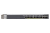
... the link partner automatically. GS728TS Front Panel 10/100/1000M Ethernet Ports Chapter 2. Physical Description | 12 Figure 2 illustrates the front panel of the NETGEAR GS728TS Smart Switch. Physical Description 2 This chapter describes the GS728TS, GS728TPS, GS752TS, and GS752TPS Smart Switch hardware features. Up to two SFP ports (port 27 and 28) at a time can be used as stacking ports. Power, Fan, and Stack Master LEDs Stack ID LED Link/Speed/ACT LEDs Combo and Dedicated SFP Ports Factory Defaults Button Reset Button...
... the link partner automatically. GS728TS Front Panel 10/100/1000M Ethernet Ports Chapter 2. Physical Description | 12 Figure 2 illustrates the front panel of the NETGEAR GS728TS Smart Switch. Physical Description 2 This chapter describes the GS728TS, GS728TPS, GS752TS, and GS752TPS Smart Switch hardware features. Up to two SFP ports (port 27 and 28) at a time can be used as stacking ports. Power, Fan, and Stack Master LEDs Stack ID LED Link/Speed/ACT LEDs Combo and Dedicated SFP Ports Factory Defaults Button Reset Button...

GS7xxTS-TPS Hardware Installation Guide
Page 15
... combo ports. Power, Fan, and Stack Master LEDs Stack ID LED Link/Speed/ACT LEDs Combo and Dedicated SFP Ports Factory Defaults Button 10/100/1000M Ethernet Ports Reset Button Figure 6. Figure 7. GS752TS Back Panel The back panel contains a power connector. GS728TS, GS728TPS, GS752TS, and GS752TPS Smart Switch Hardware Installation Guide GS752TS Front-Panel and Back-Panel Configuration The GS752TS Smart Switch has 48 10/100/1000 Mbps copper ports and 6 SFP fiber ports, 2 of sensing the line speed and negotiating the duplex mode with the link...
... combo ports. Power, Fan, and Stack Master LEDs Stack ID LED Link/Speed/ACT LEDs Combo and Dedicated SFP Ports Factory Defaults Button 10/100/1000M Ethernet Ports Reset Button Figure 6. Figure 7. GS752TS Back Panel The back panel contains a power connector. GS728TS, GS728TPS, GS752TS, and GS752TPS Smart Switch Hardware Installation Guide GS752TS Front-Panel and Back-Panel Configuration The GS752TS Smart Switch has 48 10/100/1000 Mbps copper ports and 6 SFP fiber ports, 2 of sensing the line speed and negotiating the duplex mode with the link...

GS7xxTS-TPS Hardware Installation Guide
Page 16
... connectors for each port. • Power, Fan Status, Stack Master, LED mode, PoE Max, and Stack ID LEDs. Figure 8 illustrates the front panel of which are combo ports. Each port is capable of sensing the line speed and negotiating the duplex mode with either PoE Mode or Ethernet Mode. • Recessed default reset button to restore the device back to the factory defaults • Link, Speed, and Activity LEDs for 10/100/1000 Mbps autosensing Gigabit Ethernet switching ports. • 2 Combo ports (port 47 and...
... connectors for each port. • Power, Fan Status, Stack Master, LED mode, PoE Max, and Stack ID LEDs. Figure 8 illustrates the front panel of which are combo ports. Each port is capable of sensing the line speed and negotiating the duplex mode with either PoE Mode or Ethernet Mode. • Recessed default reset button to restore the device back to the factory defaults • Link, Speed, and Activity LEDs for 10/100/1000 Mbps autosensing Gigabit Ethernet switching ports. • 2 Combo ports (port 47 and...

GS7xxTS-TPS Hardware Installation Guide
Page 32
... new changes, one path from the stack, or the unit is configured as the stacking ports. If the problem continues, contact NETGEAR technical support. GS728TS, GS728TPS, GS752TS, and GS752TPS Smart Switch Hardware Installation Guide Symptom Cause Solution ACT LED is flashing continuously on all connected ports and the network is linked to a stack, but does not join the stack. Network Adapter Cards Ensure the network adapter cards installed in this section. If you can configure the Spanning Tree Protocol (STP...
... new changes, one path from the stack, or the unit is configured as the stacking ports. If the problem continues, contact NETGEAR technical support. GS728TS, GS728TPS, GS752TS, and GS752TPS Smart Switch Hardware Installation Guide Symptom Cause Solution ACT LED is flashing continuously on all connected ports and the network is linked to a stack, but does not join the stack. Network Adapter Cards Ensure the network adapter cards installed in this section. If you can configure the Spanning Tree Protocol (STP...

GS7xxTS-TPS Hardware Installation Guide
Page 34
... ACLs (MAC, IPv4, IPv6 and TCP/UDP based) Interface GS728TS/GS752TS: • 24/48 x 10/100/1000 Mbps copper ports. • 2 x Combo ports to support 10/100/1000 Mbps copper ports or 1G/100M optical module. • 2 x SFP (slot) to support 1G optical module. • 2 x SFP (slot) to support 1G optical module (uplink) and 2.5G stacking (via stacking cable). Disabled by default. GS728TS, GS728TPS, GS752TS, and GS752TPS Smart Switch Hardware Installation Guide SNTP (Simple Network Time Protocol) 3 servers...
... ACLs (MAC, IPv4, IPv6 and TCP/UDP based) Interface GS728TS/GS752TS: • 24/48 x 10/100/1000 Mbps copper ports. • 2 x Combo ports to support 10/100/1000 Mbps copper ports or 1G/100M optical module. • 2 x SFP (slot) to support 1G optical module. • 2 x SFP (slot) to support 1G optical module (uplink) and 2.5G stacking (via stacking cable). Disabled by default. GS728TS, GS728TPS, GS752TS, and GS752TPS Smart Switch Hardware Installation Guide SNTP (Simple Network Time Protocol) 3 servers...

GS7xxTS-TPS Installation Guide
Page 1
..., use the Smart Control Center Utility to run the utility and view this screen. 2. Connect each PC to an RJ-45 network port on the Resource CD.) Prepare a PC with an Ethernet adapter and a CD ROM drive Prepare a PC with a Static IP address in Windows Start menu Programs to configure the switch. 2. Verify that includes the Smart Control Center Utility and Hardware Installation Guide. (A link to the online Software Administration Manual is...
..., use the Smart Control Center Utility to run the utility and view this screen. 2. Connect each PC to an RJ-45 network port on the Resource CD.) Prepare a PC with an Ethernet adapter and a CD ROM drive Prepare a PC with a Static IP address in Windows Start menu Programs to configure the switch. 2. Verify that includes the Smart Control Center Utility and Hardware Installation Guide. (A link to the online Software Administration Manual is...

GS7xxTS-TPS Installation Guide
Page 2
...) related information, please visit http://support.netgear.com/app/answers/detail/a_id/2649 WARNING!! NETGEAR, the NETGEAR logo, and Connect with a securely plugged in Ethernet cable, the corresponding switch LAN port status light will display the switch settings main page. and/or its MAC Address, IP Address, and model number. If you can use it to the online Reference Manual is strongly recommended. Follow this , refer to power on the Resource CD. For complete...
...) related information, please visit http://support.netgear.com/app/answers/detail/a_id/2649 WARNING!! NETGEAR, the NETGEAR logo, and Connect with a securely plugged in Ethernet cable, the corresponding switch LAN port status light will display the switch settings main page. and/or its MAC Address, IP Address, and model number. If you can use it to the online Reference Manual is strongly recommended. Follow this , refer to power on the Resource CD. For complete...

GS7xxTS-TPS Software Admin Manual
Page 7
... Port Mirroring 278 Multiple Port Mirroring 278 Chapter 8 Maintaining the System Reset 280 Device Reboot 280 Factory Default 281 Upload File From Switch 282 TFTP File Upload 282 HTTP File Upload 283 Download File To Switch 284 TFTP File Download 285 HTTP File Download 287 File Management 288 Copy 288 Dual Image Configuration 289 Dual Image Status 291 Troubleshooting 292 Ping 292 Ping IPv6 293 Traceroute 294 Chapter 9 Accessing Help Online Help 296 Support 296 User Guide 297 Registration 298 Appendix A Hardware Specifications...
... Port Mirroring 278 Multiple Port Mirroring 278 Chapter 8 Maintaining the System Reset 280 Device Reboot 280 Factory Default 281 Upload File From Switch 282 TFTP File Upload 282 HTTP File Upload 283 Download File To Switch 284 TFTP File Download 285 HTTP File Download 287 File Management 288 Copy 288 Dual Image Configuration 289 Dual Image Status 291 Troubleshooting 292 Ping 292 Ping IPv6 293 Traceroute 294 Chapter 9 Accessing Help Online Help 296 Support 296 User Guide 297 Registration 298 Appendix A Hardware Specifications...

GS7xxTS-TPS Software Admin Manual
Page 9
... and Default Values, contains hardware specifications and default values on the switches. • Chapter 3, Configuring Switching Information, describes how to manage and monitor the layer 2 switching features. • Chapter 4, Configuring Routing, describes how to manage and monitor IP routing. • Chapter 5, Configuring Quality of Service, describes how to manage the Access Control Lists (ACLs), and how to configure and operate the GS728TS, GS728TPS, GS752TS, and GS752TPS Gigabit Smart Switches by using the Web-based graphical user interface (GUI). Getting Started 1 The NETGEAR...
... and Default Values, contains hardware specifications and default values on the switches. • Chapter 3, Configuring Switching Information, describes how to manage and monitor the layer 2 switching features. • Chapter 4, Configuring Routing, describes how to manage and monitor IP routing. • Chapter 5, Configuring Quality of Service, describes how to manage the Access Control Lists (ACLs), and how to configure and operate the GS728TS, GS728TPS, GS752TS, and GS752TPS Gigabit Smart Switches by using the Web-based graphical user interface (GUI). Getting Started 1 The NETGEAR...

GS7xxTS-TPS Software Admin Manual
Page 138
... access the IGMP Snooping Configuration page, click Switching> Multicast > IGMP Snooping > IGMP Snooping Configuration. 138 When a packet with the IEEE MAC Bridge standard. Eventually, the packet is used to build forwarding lists for only a small number of the remaining network segments in the IGMP packets as they are intended to be seen or processed by class D IP addresses, which range from broadcasting the traffic to configure the parameters for example in receiving the packet. IGMP Snooping Configuration Use the IGMP Snooping Configuration...
... access the IGMP Snooping Configuration page, click Switching> Multicast > IGMP Snooping > IGMP Snooping Configuration. 138 When a packet with the IEEE MAC Bridge standard. Eventually, the packet is used to build forwarding lists for only a small number of the remaining network segments in the IGMP packets as they are intended to be seen or processed by class D IP addresses, which range from broadcasting the traffic to configure the parameters for example in receiving the packet. IGMP Snooping Configuration Use the IGMP Snooping Configuration...

GS7xxTS-TPS Software Admin Manual
Page 141
... the Fast Leave mode for the selected port(s) or LAG(s): • Admin Mode. If you want the switch to all of time you make any configuration changes, click Apply to apply the new settings to the selected interfaces. You can select multiple ports and LAGs to apply the same setting to the switch. Specify the amount of the switch. 7. Enter a value between 2 and 3600 seconds. IGMP Snooping Table Use the IGMP Snooping Table page to...
... the Fast Leave mode for the selected port(s) or LAG(s): • Admin Mode. If you want the switch to all of time you make any configuration changes, click Apply to apply the new settings to the selected interfaces. You can select multiple ports and LAGs to apply the same setting to the switch. Specify the amount of the switch. 7. Enter a value between 2 and 3600 seconds. IGMP Snooping Table Use the IGMP Snooping Table page to...

GS7xxTS-TPS Software Admin Manual
Page 145
... address to cancel the configuration on the screen and reset the data on which the last querier information is removed. Click Cancel to be used in seconds after which the query is 125. 6. The supported IGMP versions are 1 and 2. In the Querier Expiry Interval field, specify the time interval in periodic IGMP queries. Configuration changes take effect immediately 8. To access this page to the switch...
... address to cancel the configuration on the screen and reset the data on which the last querier information is removed. Click Cancel to be used in seconds after which the query is 125. 6. The supported IGMP versions are 1 and 2. In the Querier Expiry Interval field, specify the time interval in periodic IGMP queries. Configuration changes take effect immediately 8. To access this page to the switch...

GS7xxTS-TPS Software Admin Manual
Page 149
... stack member with multicast routers attached. To configure MLD Snooping settings for a particular group on that is from (2 to enable or disable MLD snooping on the interfaces (physical and lag). To configure MLD Snooping settings for a Link Aggregation Group (LAG), click LAGS. 3. Select the check box in the heading row to apply the same settings to 1 and less than the Group Membership Interval. 8. To access the MLD Snooping Configuration page, click Switching Multicast...
... stack member with multicast routers attached. To configure MLD Snooping settings for a particular group on that is from (2 to enable or disable MLD snooping on the interfaces (physical and lag). To configure MLD Snooping settings for a Link Aggregation Group (LAG), click LAGS. 3. Select the check box in the heading row to apply the same settings to 1 and less than the Group Membership Interval. 8. To access the MLD Snooping Configuration page, click Switching Multicast...

GS7xxTS-TPS Software Admin Manual
Page 152
... the VLAN. The dynamic learning mode is a member of the stack member with the ports to all interfaces. 5. To configure multicast router settings for a Link Aggregation Group (LAG), click LAGS. 3. Click Apply to apply the new settings to be enabled on the selected interface. 6. Snooping dynamic learning mode (snooping interface mode or snooping VLAN mode) does not need to the switch. To configure multicast router settings for dynamically learned multicast router information (Queries from an attached true Querier). Select the check box...
... the VLAN. The dynamic learning mode is a member of the stack member with the ports to all interfaces. 5. To configure multicast router settings for a Link Aggregation Group (LAG), click LAGS. 3. Click Apply to apply the new settings to be enabled on the selected interface. 6. Snooping dynamic learning mode (snooping interface mode or snooping VLAN mode) does not need to the switch. To configure multicast router settings for dynamically learned multicast router information (Queries from an attached true Querier). Select the check box...

GS7xxTS-TPS Software Admin Manual
Page 204
... server. Malformed packets include packets with RADIUS and other reason. Timeouts The number of a second, between the most current information. Bad authenticators and unknown types are not included as malformed accounting responses. Malformed Accounting Responses Displays the number of the supported RADIUS accounting server. GS728TS, GS728TPS, GS752TS, and GS752TPS Gigabit Smart Switches The following actions: • Click Clear Counters to reset all statistics to their default...
... server. Malformed packets include packets with RADIUS and other reason. Timeouts The number of a second, between the most current information. Bad authenticators and unknown types are not included as malformed accounting responses. Malformed Accounting Responses Displays the number of the supported RADIUS accounting server. GS728TS, GS728TPS, GS752TS, and GS752TPS Gigabit Smart Switches The following actions: • Click Clear Counters to reset all statistics to their default...

GS7xxTS-TPS Software Admin Manual
Page 234
... links to a LAG. ACLs are used to provide traffic flow control, restrict contents of routing updates, decide which can identify protocols, source, and destination IP and MAC addresses, and other packet-matching criteria. The GS728TS, GS728TPS, GS752TS, and GS752TPS switches software supports IPv4, IPv6, and MAC ACLs. Next, you create a rule and assign it to reach network resources. GS728TS, GS728TPS, GS752TS, and GS752TPS Gigabit Smart Switches Configuring Access Control Lists Access Control Lists (ACLs) ensure that only authorized users have access to specific...
... links to a LAG. ACLs are used to provide traffic flow control, restrict contents of routing updates, decide which can identify protocols, source, and destination IP and MAC addresses, and other packet-matching criteria. The GS728TS, GS728TPS, GS752TS, and GS752TPS switches software supports IPv4, IPv6, and MAC ACLs. Next, you create a rule and assign it to reach network resources. GS728TS, GS728TPS, GS752TS, and GS752TPS Gigabit Smart Switches Configuring Access Control Lists Access Control Lists (ACLs) ensure that only authorized users have access to specific...

GS7xxTS-TPS Software Admin Manual
Page 304
... Boot code update DHCP/manual IP Default gateway System name configuration Configuration save/restore Firmware upgrade Restore defaults Dual image support Factory reset Sets Supported 1 1 1 1 1 1 1 (Web and front-panel button) 1 1 Default N/A DHCP enabled/192.168.0.239 192.168.0.254 NULL N/A N/A N/A Enabled N/A System Management Feature Multi-session Web connections SNMPv1/V2c SNMP v3 Time control LLDP/LLDP-MED Logging MIB support Smart Control Center Statistics Sets Supported 16 Max 5 community entries 1 (Local or SNTP) All ports 3 (Memory/Flash/Server) 1 N/A N/A Default Enabled Enabled...
... Boot code update DHCP/manual IP Default gateway System name configuration Configuration save/restore Firmware upgrade Restore defaults Dual image support Factory reset Sets Supported 1 1 1 1 1 1 1 (Web and front-panel button) 1 1 Default N/A DHCP enabled/192.168.0.239 192.168.0.254 NULL N/A N/A N/A Enabled N/A System Management Feature Multi-session Web connections SNMPv1/V2c SNMP v3 Time control LLDP/LLDP-MED Logging MIB support Smart Control Center Statistics Sets Supported 16 Max 5 community entries 1 (Local or SNTP) All ports 3 (Memory/Flash/Server) 1 N/A N/A Default Enabled Enabled...

GS7xxTS-TPS Software Admin Manual
Page 308
... routing updates, decide which types of its tag to leave port 2 as an untagged packet. They can also be used in firewall routers that packets entering these ports are tagged with VLAN ID 20. GS728TS, GS728TPS, GS752TS, and GS752TPS Gigabit Smart Switches 2. ACLs are normally used on page 113), specify the PVID for the network. Access lists are positioned between two parts of the network to control the traffic entering or exiting a specific part...
... routing updates, decide which types of its tag to leave port 2 as an untagged packet. They can also be used in firewall routers that packets entering these ports are tagged with VLAN ID 20. GS728TS, GS728TPS, GS752TS, and GS752TPS Gigabit Smart Switches 2. ACLs are normally used on page 113), specify the PVID for the network. Access lists are positioned between two parts of the network to control the traffic entering or exiting a specific part...


