
GS7xxTS-TPS Hardware Installation Guide
Page 8
... 100/1000Mbps SFP slots and two 2.5Gbps ports for stacking. • Full NETGEAR Smart Switch functionality. • Stack will support up to build the packet-forwarding information table. Introduction GS728TS, GS728TPS, GS752TS, and GS752TPS Smart Switch Hardware Installation Guide • 2 x SFP ... support 1G optical module. • 2 x SFP (slot) to support 1G optical module (uplink) or 2.5G stacking (via MDI Enhancements) • PoE • GS728TPS: Port 1-8 support both IEEE802.3 at and af, and port 9-24 support IEEE802.3af. • GS752TPS: Port 1-8 support both IEEE802.3 at and af...
... 100/1000Mbps SFP slots and two 2.5Gbps ports for stacking. • Full NETGEAR Smart Switch functionality. • Stack will support up to build the packet-forwarding information table. Introduction GS728TS, GS728TPS, GS752TS, and GS752TPS Smart Switch Hardware Installation Guide • 2 x SFP ... support 1G optical module. • 2 x SFP (slot) to support 1G optical module (uplink) or 2.5G stacking (via MDI Enhancements) • PoE • GS728TPS: Port 1-8 support both IEEE802.3 at and af, and port 9-24 support IEEE802.3af. • GS752TPS: Port 1-8 support both IEEE802.3 at and af...

GS7xxTS-TPS Hardware Installation Guide
Page 9
...Energy Efficient Ethernet) compliance. Switch software is connected to configure different ID assignments. GS728TS, GS728TPS, GS752TS, and GS752TPS Smart Switch Hardware Installation Guide • GS7xxTPS model LEDs: Power and... Status LED, FAN status LED, Master LED, LED mode LED and Max PoE LED. • Stack ID LED to display stack member ID (1-6). • Store-... and power LED. • Internal open frame power supply. • Standard NETGEAR 7xx series chassis. • NETGEAR Green product series power-saving features: • Automatic power consumption adjustment based on...
...Energy Efficient Ethernet) compliance. Switch software is connected to configure different ID assignments. GS728TS, GS728TPS, GS752TS, and GS752TPS Smart Switch Hardware Installation Guide • GS7xxTPS model LEDs: Power and... Status LED, FAN status LED, Master LED, LED mode LED and Max PoE LED. • Stack ID LED to display stack member ID (1-6). • Store-... and power LED. • Internal open frame power supply. • Standard NETGEAR 7xx series chassis. • NETGEAR Green product series power-saving features: • Automatic power consumption adjustment based on...

GS7xxTS-TPS Hardware Installation Guide
Page 13
... the front panel of which are combo ports. Figure 3. Power Connector GS728TPS Front-Panel and Back-Panel Configuration The GS728TPS Smart Switch has 24 10/100/1000 Mbps PoE capable copper ports and 6 SFP fiber ports, 2 of the NETGEAR GS728TPS Smart Switch. GS728TS, GS728TPS, GS752TS, and GS752TPS Smart Switch Hardware Installation Guide The front panel contains...
... the front panel of which are combo ports. Figure 3. Power Connector GS728TPS Front-Panel and Back-Panel Configuration The GS728TPS Smart Switch has 24 10/100/1000 Mbps PoE capable copper ports and 6 SFP fiber ports, 2 of the NETGEAR GS728TPS Smart Switch. GS728TS, GS728TPS, GS752TS, and GS752TPS Smart Switch Hardware Installation Guide The front panel contains...

GS7xxTS-TPS Hardware Installation Guide
Page 14
Figure 5 illustrates the NETGEAR GS728TPS Smart Switch back panel. Figure 5. GS728TPS Back Panel The back panel contains a power connector. 14 | Chapter 2. GS728TS, GS728TPS, GS752TS, and GS752TPS Smart Switch Hardware Installation Guide Power, Fan, LED mode, PoE Max, and Stack Master LEDs Stack ID LED Link/...ACT LEDs Combo and Dedicated SFP Ports Factory Defaults Button Reset Button Select Button 10/100/1000M PoE capable Ethernet Ports Figure 4. Physical Description Power Connector GS728TPS Front Panel The front panel contains the following: • 24 RJ-45 connectors for 10...
Figure 5 illustrates the NETGEAR GS728TPS Smart Switch back panel. Figure 5. GS728TPS Back Panel The back panel contains a power connector. 14 | Chapter 2. GS728TS, GS728TPS, GS752TS, and GS752TPS Smart Switch Hardware Installation Guide Power, Fan, LED mode, PoE Max, and Stack Master LEDs Stack ID LED Link/...ACT LEDs Combo and Dedicated SFP Ports Factory Defaults Button Reset Button Select Button 10/100/1000M PoE capable Ethernet Ports Figure 4. Physical Description Power Connector GS728TPS Front Panel The front panel contains the following: • 24 RJ-45 connectors for 10...

GS7xxTS-TPS Hardware Installation Guide
Page 16
... Select Button Link/Speed/ACT LEDs Combo and Dedicated SFP Ports Factory Defaults Button 10/100/1000M PoE capable Ethernet Ports Reset Button Figure 8. GS728TS, GS728TPS, GS752TS, and GS752TPS Smart Switch Hardware Installation Guide GS752TPS Front-Panel and Back-Panel Configuration The... GS752TPS Smart Switch has 48 10/100/1000 Mbps PoE capable copper ports and 6 SFP fiber ports, 2 of the NETGEAR GS752TPS Smart Switch. ...
... Select Button Link/Speed/ACT LEDs Combo and Dedicated SFP Ports Factory Defaults Button 10/100/1000M PoE capable Ethernet Ports Reset Button Figure 8. GS728TS, GS728TPS, GS752TS, and GS752TPS Smart Switch Hardware Installation Guide GS752TPS Front-Panel and Back-Panel Configuration The... GS752TPS Smart Switch has 48 10/100/1000 Mbps PoE capable copper ports and 6 SFP fiber ports, 2 of the NETGEAR GS752TPS Smart Switch. ...

GS7xxTS-TPS Hardware Installation Guide
Page 17
...Ethernet LED will change to that port: - Physical Description | 17 GS752TPS Back Panel The back panel contains a power connector. PoE power demand exceeds the power available. - LED Designations Power Connector RJ-45 Port LEDs The following failures resulted in stopping power...Mbps link is transmitting or receiving packets at 10/100 Mbps. GS728TS, GS728TPS, GS752TS, and GS752TPS Smart Switch Hardware Installation Guide Figure 9. Chapter 2. PoE Mode: PoE Status LED • Off - Short circuit on the PoE power circuit. - Out of the following table describes the RJ-45...
...Ethernet LED will change to that port: - Physical Description | 17 GS752TPS Back Panel The back panel contains a power connector. PoE power demand exceeds the power available. - LED Designations Power Connector RJ-45 Port LEDs The following failures resulted in stopping power...Mbps link is transmitting or receiving packets at 10/100 Mbps. GS728TS, GS728TPS, GS752TS, and GS752TPS Smart Switch Hardware Installation Guide Figure 9. Chapter 2. PoE Mode: PoE Status LED • Off - Short circuit on the PoE power circuit. - Out of the following table describes the RJ-45...

GS7xxTS-TPS Hardware Installation Guide
Page 19
... technology compensates for attaching devices, all RJ-45 ports support Auto Uplink. The last two SFP ports can be used at least 7W of PoE power available for another device. • Solid Green -The Port LED is available. • Solid Yellow - There is a straight-through... LED was active in PoE Mode. To simplify the procedure for setting uplink connections, while eliminating concern about whether to a PC) or an "uplink" connection (such as stacking ports. GS728TS, GS728TPS, GS752TS, and GS752TPS Smart Switch Hardware Installation Guide LED Max PoE LED LED Mode LED Designation ...
... technology compensates for attaching devices, all RJ-45 ports support Auto Uplink. The last two SFP ports can be used at least 7W of PoE power available for another device. • Solid Green -The Port LED is available. • Solid Yellow - There is a straight-through... LED was active in PoE Mode. To simplify the procedure for setting uplink connections, while eliminating concern about whether to a PC) or an "uplink" connection (such as stacking ports. GS728TS, GS728TPS, GS752TS, and GS752TPS Smart Switch Hardware Installation Guide LED Max PoE LED LED Mode LED Designation ...
GS7xxTS-TPS Hardware Installation Guide
Page 20
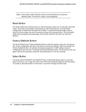
.... Reset Button The Smart Switch has a Reset button on . The last saved configuration is recommended to be used as a stacking cable. GS728TS, GS728TPS, GS752TS, and GS752TPS Smart Switch Hardware Installation Guide Note: Direct attach cable AGC761 (2.5G) is loaded into the switch as it resets. Factory Defaults...cable is equivalent to powering the unit off and back on the front panel to change the LED mode of the ports between Ethernet and PoE status. Physical Description This action is sold separately. To operate the Reset button, insert a device such as a paper clip into the...
.... Reset Button The Smart Switch has a Reset button on . The last saved configuration is recommended to be used as a stacking cable. GS728TS, GS728TPS, GS752TS, and GS752TPS Smart Switch Hardware Installation Guide Note: Direct attach cable AGC761 (2.5G) is loaded into the switch as it resets. Factory Defaults...cable is equivalent to powering the unit off and back on the front panel to change the LED mode of the ports between Ethernet and PoE status. Physical Description This action is sold separately. To operate the Reset button, insert a device such as a paper clip into the...

GS7xxTS-TPS Hardware Installation Guide
Page 34
.../Activity Per device: Power, Fan, Stack Master, Stack ID Per device (for GS7xxTPS): LED mode and PoE Max 34 | Appendix : Technical Specifications Disabled by default. Stacking Ports: • GS728TS/GS728TPS: Port 27 and port 28 can be used as the stacking ports or as uplink ports. • GS752TS.../GS752TPS: Port 51 and port 52 can be used as the stacking ports or as uplink ports. GS728TPS/GS752TPS: • 24/48 PoE-capable 10/100/1000 Mbps copper ports (8 PoE+ capable). • 2 x Combo ports to support 10/100/1000 Mbps copper ports or 1G/100M optical module •...
.../Activity Per device: Power, Fan, Stack Master, Stack ID Per device (for GS7xxTPS): LED mode and PoE Max 34 | Appendix : Technical Specifications Disabled by default. Stacking Ports: • GS728TS/GS728TPS: Port 27 and port 28 can be used as the stacking ports or as uplink ports. • GS752TS.../GS752TPS: Port 51 and port 52 can be used as the stacking ports or as uplink ports. GS728TPS/GS752TPS: • 24/48 PoE-capable 10/100/1000 Mbps copper ports (8 PoE+ capable). • 2 x Combo ports to support 10/100/1000 Mbps copper ports or 1G/100M optical module •...

GS7xxTS-TPS Hardware Installation Guide
Page 35
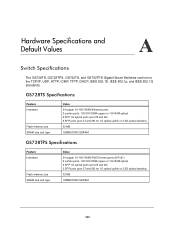
... GS728TS/TPS, 104 Gbps for GS752TS/TPS Stacking up to 6 switches Address database size: 16K media access control (MAC) addresses per system PoE power budget: • GS728TPS: Maximum 192W • GS752TPS: Maximum 384W Mean Time Between Failure (MTBF): • GS728TS: • 595422.68 hours (~68.9 years...67929.0 hours (~7.8 years) at 55°C Power Supply GS752TPS • AC Voltage: 100-240 V • Frequency: 50-60 Hz • Amperage (max): 8A GS728TPS • AC Voltage: 100-240 V • Frequency: 47-63 Hz • Amperage (max): 4A GS752TS • AC Voltage: 100-240 V • ...
... GS728TS/TPS, 104 Gbps for GS752TS/TPS Stacking up to 6 switches Address database size: 16K media access control (MAC) addresses per system PoE power budget: • GS728TPS: Maximum 192W • GS752TPS: Maximum 384W Mean Time Between Failure (MTBF): • GS728TS: • 595422.68 hours (~68.9 years...67929.0 hours (~7.8 years) at 55°C Power Supply GS752TPS • AC Voltage: 100-240 V • Frequency: 50-60 Hz • Amperage (max): 8A GS728TPS • AC Voltage: 100-240 V • Frequency: 47-63 Hz • Amperage (max): 4A GS752TS • AC Voltage: 100-240 V • ...

GS7xxTS-TPS Software Admin Manual
Page 4
..., and GS752TPS Gigabit Smart Switches PoE/PoE+ (GS728TPS and GS752TPS Only 70 PoE Configuration 70 PoE Port Configuration 72 SNMP 75 SNMPv1/v2 75 Trap Configuration 77 Trap Flags 78 SNMP Supported MIBs 79 SNMP v3 User ...88 Services - DHCP Snooping 92 DHCP Snooping Global Configuration 93 Interface Configuration 94 Binding Configuration 95 Persistent Configuration 97 Statistics 98 Timer Schedule (GS728TPS and GS752TPS Only 99 Timer Global Configuration 99 Timer Schedule Configuration 100 Chapter 3 Configuring Switching Information Ports 102 Port Configuration 102 Flow Control...
..., and GS752TPS Gigabit Smart Switches PoE/PoE+ (GS728TPS and GS752TPS Only 70 PoE Configuration 70 PoE Port Configuration 72 SNMP 75 SNMPv1/v2 75 Trap Configuration 77 Trap Flags 78 SNMP Supported MIBs 79 SNMP v3 User ...88 Services - DHCP Snooping 92 DHCP Snooping Global Configuration 93 Interface Configuration 94 Binding Configuration 95 Persistent Configuration 97 Statistics 98 Timer Schedule (GS728TPS and GS752TPS Only 99 Timer Global Configuration 99 Timer Schedule Configuration 100 Chapter 3 Configuring Switching Information Ports 102 Port Configuration 102 Flow Control...

GS7xxTS-TPS Software Admin Manual
Page 9
...This manual describes the software configuration procedures and explains the options available within those procedures. Document Organization The GS728TS, GS728TPS, GS752TS, and GS752TPS Smart Switch Software Administration Manual contains the following chapters: • Chapter 1, Getting Started... 9, Accessing Help, describes how to configure administrative features such as SNMP, DHCP, PoE, and Green Ethernet. 1. Getting Started 1 The NETGEAR®GS728TS, GS728TPS, GS752TS, and GS752TPS Smart Switch Software Administration Manual describes how to configure and operate the ...
...This manual describes the software configuration procedures and explains the options available within those procedures. Document Organization The GS728TS, GS728TPS, GS752TS, and GS752TPS Smart Switch Software Administration Manual contains the following chapters: • Chapter 1, Getting Started... 9, Accessing Help, describes how to configure administrative features such as SNMP, DHCP, PoE, and Green Ethernet. 1. Getting Started 1 The NETGEAR®GS728TS, GS728TPS, GS752TS, and GS752TPS Smart Switch Software Administration Manual describes how to configure and operate the ...
GS7xxTS-TPS Software Admin Manual
Page 31
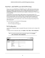
DHCP Snooping on page 92 • Timer Schedule (GS728TPS and GS752TPS Only) on page 80 • Services - The System tab contains links to the following pages: • System Information on page 32 • Slot ... on page 51 31 From the Management link, you can access the following features: • Management on page 31 • Stacking on page 61 • PoE/PoE+ (GS728TPS and GS752TPS Only) on page 70 • SNMP on page 75 • LLDP on page 99 Management This section describes how to its environment. 2. Configuring...
DHCP Snooping on page 92 • Timer Schedule (GS728TPS and GS752TPS Only) on page 80 • Services - The System tab contains links to the following pages: • System Information on page 32 • Slot ... on page 51 31 From the Management link, you can access the following features: • Management on page 31 • Stacking on page 61 • PoE/PoE+ (GS728TPS and GS752TPS Only) on page 70 • SNMP on page 75 • LLDP on page 99 Management This section describes how to its environment. 2. Configuring...
GS7xxTS-TPS Software Admin Manual
Page 70
....3af) ports that the power budget for ports. The GS728TPS can also access the PoE Configuration page by clicking System > PoE > Advanced > PoE Configuration. 70 Each port is used effectively. GS728TS, GS728TPS, GS752TS, and GS752TPS Gigabit Smart Switches PoE/PoE+ (GS728TPS and GS752TPS Only) Ports g1-g8 on the GS728TPS and GS752TPS are capable of delivering up to 30W...
....3af) ports that the power budget for ports. The GS728TPS can also access the PoE Configuration page by clicking System > PoE > Advanced > PoE Configuration. 70 Each port is used effectively. GS728TS, GS728TPS, GS752TS, and GS752TPS Gigabit Smart Switches PoE/PoE+ (GS728TPS and GS752TPS Only) Ports g1-g8 on the GS728TPS and GS752TPS are capable of delivering up to 30W...
GS7xxTS-TPS Software Admin Manual
Page 71
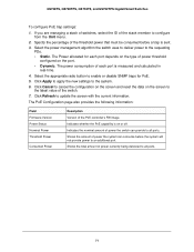
... the switch uses to deliver power to the system. 6. Indicates the nominal amount of the switch. 7. GS728TS, GS728TPS, GS752TS, and GS752TPS Gigabit Smart Switches To configure PoE trap settings: 1. Click Apply to apply the new settings to the requesting PDs. • Static. Click Cancel ...to the latest value of power the switch can consume before a trap is measured and calculated in real-time. 4. The PoE Configuration page also provides the following information: Field Firmware Version Power Status Nominal Power Threshold Power Consumed Power Description Version of the ...
... the switch uses to deliver power to the system. 6. Indicates the nominal amount of the switch. 7. GS728TS, GS728TPS, GS752TS, and GS752TPS Gigabit Smart Switches To configure PoE trap settings: 1. Click Apply to apply the new settings to the requesting PDs. • Static. Click Cancel ...to the latest value of power the switch can consume before a trap is measured and calculated in real-time. 4. The PoE Configuration page also provides the following information: Field Firmware Version Power Status Nominal Power Threshold Power Consumed Power Description Version of the ...
GS7xxTS-TPS Software Admin Manual
Page 72
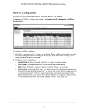
GS728TS, GS728TPS, GS752TS, and GS752TPS Gigabit Smart Switches PoE Port Configuration Use the PoE Port Configuration page to each selected port. Select multiple check boxes to apply the same settings to configure per-port PoE settings. Configure or view the settings: • Admin Mode. Shows ...disable the ability of the port to configure. Determine which ports can supply power. To display the PoE Port Configuration page, click System > PoE > Advanced > PoE Port Configuration. To configure PoE Port settings: 1. Select the check box next to the port to deliver power. • ...
GS728TS, GS728TPS, GS752TS, and GS752TPS Gigabit Smart Switches PoE Port Configuration Use the PoE Port Configuration page to each selected port. Select multiple check boxes to apply the same settings to configure per-port PoE settings. Configure or view the settings: • Admin Mode. Shows ...disable the ability of the port to configure. Determine which ports can supply power. To display the PoE Port Configuration page, click System > PoE > Advanced > PoE Port Configuration. To configure PoE Port settings: 1. Select the check box next to the port to deliver power. • ...

GS7xxTS-TPS Software Admin Manual
Page 78
GS728TS, GS728TPS, GS752TS, and GS752TPS Gigabit Smart Switches Trap Flags The pages in the Trap Manager folder allow you make any enabled SNMP Trap Receivers, and a message ... to the switch. To access the Trap Flags page, click System > SNMP > SNMP V1/V2 > Trap Flags. For the GS728TPS and GS752TPS switches, use the PoE field to the latest value of PoE traps. The factory default is Enable. 2. From the Link Up/Down field, enable or disable activation of link status traps...
GS728TS, GS728TPS, GS752TS, and GS752TPS Gigabit Smart Switches Trap Flags The pages in the Trap Manager folder allow you make any enabled SNMP Trap Receivers, and a message ... to the switch. To access the Trap Flags page, click System > SNMP > SNMP V1/V2 > Trap Flags. For the GS728TPS and GS752TPS switches, use the PoE field to the latest value of PoE traps. The factory default is Enable. 2. From the Link Up/Down field, enable or disable activation of link status traps...

GS7xxTS-TPS Software Admin Manual
Page 91
GS728TS, GS728TPS, GS752TS, and GS752TPS Gigabit Smart Switches Field MED Details Capabilities Supported Current Capabilities Device Class PoE Device Type PoE Power Source PoE Power Priority PoE Power Value Hardware Revision Firmware Revision Software Revision Serial Number Model Name Asset ID Location ... (ECS) Emergency Location Identification Number (ELIN) the remote device has advertised in MED TLV from the device. Displays the port PoE type. Displays the software version advertised by the remote device. Specifies the advertised capabilities that were received in the location TLV,...
GS728TS, GS728TPS, GS752TS, and GS752TPS Gigabit Smart Switches Field MED Details Capabilities Supported Current Capabilities Device Class PoE Device Type PoE Power Source PoE Power Priority PoE Power Value Hardware Revision Firmware Revision Software Revision Serial Number Model Name Asset ID Location ... (ECS) Emergency Location Identification Number (ELIN) the remote device has advertised in MED TLV from the device. Displays the port PoE type. Displays the software version advertised by the remote device. Specifies the advertised capabilities that were received in the location TLV,...

GS7xxTS-TPS Software Admin Manual
Page 99
... Note: The Timer Schedule feature must be enabled for the PoE ports. To display the Timer Global Configuration page, click System > Timer Global Configuration. GS728TS, GS728TPS, GS752TS, and GS752TPS Gigabit Smart Switches Timer Schedule (GS728TPS and GS752TPS Only) Timers control when power can and cannot be... timer settings: 99 Use the following pages: • Timer Global Configuration on page 99 • Timer Schedule Configuration on the PoE Port Configuration page. From the Timer Schedule link, you can access the following general steps to add a timer to control the ...
... Note: The Timer Schedule feature must be enabled for the PoE ports. To display the Timer Global Configuration page, click System > Timer Global Configuration. GS728TS, GS728TPS, GS752TS, and GS752TPS Gigabit Smart Switches Timer Schedule (GS728TPS and GS752TPS Only) Timers control when power can and cannot be... timer settings: 99 Use the following pages: • Timer Global Configuration on page 99 • Timer Schedule Configuration on the PoE Port Configuration page. From the Timer Schedule link, you can access the following general steps to add a timer to control the ...
GS7xxTS-TPS Software Admin Manual
Page 300
... 27 and 28) for 1G optical uplink or 2.5G optical stacking 32 MB 128MB DDR2 SDRAM GS728TPS Specifications Feature Interfaces Flash memory size SRAM size and type Value 24 copper 10/100/1000M PoE Ethernet ports (8 PoE+) 2 combo ports: 10/100/1000M copper or 1G/100M optical 2 SFP 1G optical ports (port 25...
... 27 and 28) for 1G optical uplink or 2.5G optical stacking 32 MB 128MB DDR2 SDRAM GS728TPS Specifications Feature Interfaces Flash memory size SRAM size and type Value 24 copper 10/100/1000M PoE Ethernet ports (8 PoE+) 2 combo ports: 10/100/1000M copper or 1G/100M optical 2 SFP 1G optical ports (port 25...
