
GS7xxTPS Hardware manual
Page 31
... Smart Switch Table 3-2. Indicates the Up/Down stacking port link is disconnected. • Solid Green - Indicates that there is available. • Flashing Yellow - The Stack Master LED is lit if there is an active stack link, and the unit is operating normally. • Off - Power is supplied to the switch and is in Ethernet LED Mode (default). • Solid Yellow - Switch acts as a slave member in a stack of switches. • Solid Green - System LEDs LED Power LED FAN LED...
... Smart Switch Table 3-2. Indicates the Up/Down stacking port link is disconnected. • Solid Green - Indicates that there is available. • Flashing Yellow - The Stack Master LED is lit if there is an active stack link, and the unit is operating normally. • Off - Power is supplied to the switch and is in Ethernet LED Mode (default). • Solid Yellow - Switch acts as a slave member in a stack of switches. • Solid Green - System LEDs LED Power LED FAN LED...
GS7xxTPS Hardware manual
Page 36
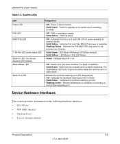
... the Ethernet limitations. If you are combo links, use the Web Management to Default" button. To reset the switch, disconnect the AC power from the stack. Troubleshooting Chart Symptom Cause Solution ACT LED is flashing continuously on all connected ports and the network is linked to the support information card included with combo links used as a stand-alone unit. Network Adapter Cards Ensure the network adapter cards installed in this section. A network loop (redundant path) has been created. Switch...
... the Ethernet limitations. If you are combo links, use the Web Management to Default" button. To reset the switch, disconnect the AC power from the stack. Troubleshooting Chart Symptom Cause Solution ACT LED is flashing continuously on all connected ports and the network is linked to the support information card included with combo links used as a stand-alone unit. Network Adapter Cards Ensure the network adapter cards installed in this section. A network loop (redundant path) has been created. Switch...
GS7xxTPS Quick Install Guide
Page 1
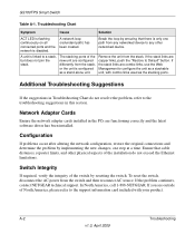
..., 2009 5:56 PM )NSTALLATION'UIDE NETGEAR Gigabit Smart Switch GS700TPS Follow these instructions to set up your network. The Installation Wizard will guide you are using DHCP in your network, configure the switch IP address before connecting it to your switch, verify that the cable connections are using static IP addressing in your smart switch. In the absence of the Resource CD, especially the reference manuals on the Switch front panel. Connect each PC to install the Smart Wizard Discovery. 3.
..., 2009 5:56 PM )NSTALLATION'UIDE NETGEAR Gigabit Smart Switch GS700TPS Follow these instructions to set up your network. The Installation Wizard will guide you are using DHCP in your network, configure the switch IP address before connecting it to your switch, verify that the cable connections are using static IP addressing in your smart switch. In the absence of the Resource CD, especially the reference manuals on the Switch front panel. Connect each PC to install the Smart Wizard Discovery. 3.
GS7xxTPS Quick Install Guide
Page 2
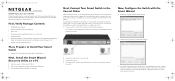
...://www.NETGEAR.com/register. Turn on the smart switch and wait two minutes. 3. If your product and use our telephone support service. After installing your device, locate the serial number on computer connected to view the switch log in Ethernet cable, the corresponding smart switch LAN port status light will be treated and recycled in your jurisdiction implementing the WEEE Directive. © 2009 by NETGEAR, Inc. If disposed of your network uses static IP addresses, be configured to configure...
...://www.NETGEAR.com/register. Turn on the smart switch and wait two minutes. 3. If your product and use our telephone support service. After installing your device, locate the serial number on computer connected to view the switch log in Ethernet cable, the corresponding smart switch LAN port status light will be treated and recycled in your jurisdiction implementing the WEEE Directive. © 2009 by NETGEAR, Inc. If disposed of your network uses static IP addresses, be configured to configure...
GS7xxTPS User Manual
Page 10
....0, June 2009 About This Manual The NETGEAR® GS700TPS Smart Switch Software Administration Manual describes how to install and configure the GS700TPS Smart Switch in this manual is intended for readers with intermediate to configure QoS functions. How to Use This Book This document describes configuration commands for the system administrator who wishes to install, configure, operate, and troubleshoot the GS700TPS Gigabit Stackable PoE Smart Switch using the remaining factory default parameters. This user guide assumes that you can communicate...
....0, June 2009 About This Manual The NETGEAR® GS700TPS Smart Switch Software Administration Manual describes how to install and configure the GS700TPS Smart Switch in this manual is intended for readers with intermediate to configure QoS functions. How to Use This Book This document describes configuration commands for the system administrator who wishes to install, configure, operate, and troubleshoot the GS700TPS Gigabit Stackable PoE Smart Switch using the remaining factory default parameters. This user guide assumes that you can communicate...
GS7xxTPS User Manual
Page 15
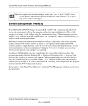
... hardware installation instructions, refer to the GS700TPS Smart Switch Hardware Installation Manual included on your switch for the first time, the SmartWizard Discovery utility enables you can monitor the performance of the SmartWizard Discovery utility and Web Management interface are shown in the table below. The management software enables you can set up VLANs, traffic priority, and configure port trunking. Using your browser, for managing and monitoring switch functions. When you power up your network segment. Web-Based Management enables you into the Web Management interface...
... hardware installation instructions, refer to the GS700TPS Smart Switch Hardware Installation Manual included on your switch for the first time, the SmartWizard Discovery utility enables you can monitor the performance of the SmartWizard Discovery utility and Web Management interface are shown in the table below. The management software enables you can set up VLANs, traffic priority, and configure port trunking. Using your browser, for managing and monitoring switch functions. When you power up your network segment. Web-Based Management enables you into the Web Management interface...

GS7xxTPS User Manual
Page 18
... power adapter. Start the SmartWizard Discovery utility. 5. Then use this screen to proceed to your network has DHCP service. Proceed as follows: 1. The default IP is password. GS700TPS Smart Switch Software Administration Manual 8. Power on your switch. Install the SmartWizard Discovery utility on the switch by plugging in Chapter 2, "Introduction to your GS700TPS Gigabit Stackable PoE Smart Switch. You should see a screen similar to that shown in to the web-based switch management utility Manually...
... power adapter. Start the SmartWizard Discovery utility. 5. Then use this screen to proceed to your network has DHCP service. Proceed as follows: 1. The default IP is password. GS700TPS Smart Switch Software Administration Manual 8. Power on your switch. Install the SmartWizard Discovery utility on the switch by plugging in Chapter 2, "Introduction to your GS700TPS Gigabit Stackable PoE Smart Switch. You should see a screen similar to that shown in to the web-based switch management utility Manually...
GS7xxTPS User Manual
Page 19
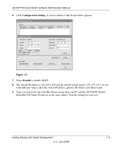
... your password and click Set. Click Configuration Setting. If you want different values, enter the switch IP address, gateway IP address and subnet mask. 9. Getting Started with Switch Management 1-6 v1.0, June 2009 GS700TPS Smart Switch Software Administration Manual 6. Type your PC and the GS700TPS Gigabit Stackable PoE Smart Switch are in the same subnet. Note the settings for later use. Please ensure that shown below appears. A screen similar to disable DHCP. 8. The default IP address is...
... your password and click Set. Click Configuration Setting. If you want different values, enter the switch IP address, gateway IP address and subnet mask. 9. Getting Started with Switch Management 1-6 v1.0, June 2009 GS700TPS Smart Switch Software Administration Manual 6. Type your PC and the GS700TPS Gigabit Stackable PoE Smart Switch are in the same subnet. Note the settings for later use. Please ensure that shown below appears. A screen similar to disable DHCP. 8. The default IP address is...
GS7xxTPS User Manual
Page 26
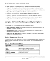
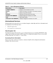
... easily configure the device from remote locations. Clears logs. 2-3 Introduction to tables or information windows. Provides access to informational services including technical support, online help and support. Device Management Buttons Button Name Description ADD APPLY CANCEL CLEAR ALL CLEAR ALL COUNTERS CLEAR LOGS Adds information to the Web Browser Interface v1.0, June 2009 Resets statistics counters. Applies configured changes to the device. Provides an explanation of this manual: • Chapter 3, "Managing System Settings" describes how to configure the...
... easily configure the device from remote locations. Clears logs. 2-3 Introduction to tables or information windows. Provides access to informational services including technical support, online help and support. Device Management Buttons Button Name Description ADD APPLY CANCEL CLEAR ALL CLEAR ALL COUNTERS CLEAR LOGS Adds information to the Web Browser Interface v1.0, June 2009 Resets statistics counters. Applies configured changes to the device. Provides an explanation of this manual: • Chapter 3, "Managing System Settings" describes how to configure the...
GS7xxTPS User Manual
Page 27
... data. For a detailed description of how to the selected screen. Tests copper cables. Accessing Device Information Each screen of a LAG. Device Management Buttons Button Name Description CURRENT MEMBERS DELETE GO REFRESH TAGGED PORT MEMBERS TEST UNTAGGED PORT MEMBERS Displays current members of the web browser interface contains a help and device information and are displayed in PDF format. Deletes information from tables or information windows. GS700TPS Smart Switch Software Administration Manual Table...
... data. For a detailed description of how to the selected screen. Tests copper cables. Accessing Device Information Each screen of a LAG. Device Management Buttons Button Name Description CURRENT MEMBERS DELETE GO REFRESH TAGGED PORT MEMBERS TEST UNTAGGED PORT MEMBERS Displays current members of the web browser interface contains a help and device information and are displayed in PDF format. Deletes information from tables or information windows. GS700TPS Smart Switch Software Administration Manual Table...
GS7xxTPS User Manual
Page 51
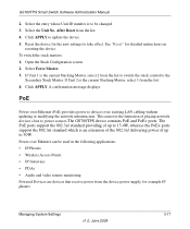
... power supply, for detailed instructions on resetting the device. Click APPLY. The PoE ports support the 802.3af standard providing of placing network devices close to power sources.The GS700TPS device contains PoE and PoE+ ports. Click APPLY to take effect. Reset the device for the new settings to update the device. 5. A confirmation message displays. To switch the stack masters: 1. Open the Stack Configuration screen. 2. PoE Power-over-Ethernet (PoE) provides power to be used...
... power supply, for detailed instructions on resetting the device. Click APPLY. The PoE ports support the 802.3af standard providing of placing network devices close to power sources.The GS700TPS device contains PoE and PoE+ ports. Click APPLY to take effect. Reset the device for the new settings to update the device. 5. A confirmation message displays. To switch the stack masters: 1. Open the Stack Configuration screen. 2. PoE Power-over-Ethernet (PoE) provides power to be used...

GS7xxTPS User Manual
Page 80
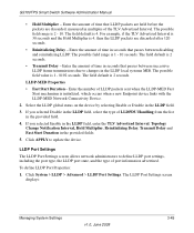
...-MED Network Connectivity Device. 2. GS700TPS Smart Switch Software Administration Manual • LLDPDU Handling - The field default is 1 - 10 seconds. If you selected Disable in the LLDP field, select the type of time in seconds that occurred. Enter the amount of the TLV Advertised Interval. Displays the amount of times LLDP packets are flooded to update the device. 3-46 v1.0, June 2009 Managing System Settings The...
...-MED Network Connectivity Device. 2. GS700TPS Smart Switch Software Administration Manual • LLDPDU Handling - The field default is 1 - 10 seconds. If you selected Disable in the LLDP field, select the type of time in seconds that occurred. Enter the amount of the TLV Advertised Interval. Displays the amount of times LLDP packets are flooded to update the device. 3-46 v1.0, June 2009 Managing System Settings The...
GS7xxTPS User Manual
Page 83
.... To define LLDP Port Properties: 1. The field default is 2 - 10. Select the LLDP global status on the device by selecting Enable or Disable in the provided fields. 5. LLDP Port Settings The LLDP Port Settings screen allows network administrators to define LLDP port settings, including the port type, the LLDP port state, and the type of time in the LLDP local systems MIB. GS700TPS Smart Switch Software Administration Manual • Hold Multiplier...
.... To define LLDP Port Properties: 1. The field default is 2 - 10. Select the LLDP global status on the device by selecting Enable or Disable in the provided fields. 5. LLDP Port Settings The LLDP Port Settings screen allows network administrators to define LLDP port settings, including the port type, the LLDP port state, and the type of time in the LLDP local systems MIB. GS700TPS Smart Switch Software Administration Manual • Hold Multiplier...

GS7xxTPS User Manual
Page 91
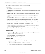
...; Auto-Negotiation Enabled - False - False - For example, 1000BASE-T half duplex mode, 100BASE-TX full duplex mode. • Operational MAU Type - Indicates the TLV is currently aggregated. • Aggregation Port ID - Managing System Settings v1.0, June 2009 3-57 Displays the port number. The possible values are : - True - Displays the advertised maximum frame size supported on the port. - Indicates if the port can be aggregated. • Aggregation status - Displays the port speed auto-negotiation active status. Displays the advertised aggregated port...
...; Auto-Negotiation Enabled - False - False - For example, 1000BASE-T half duplex mode, 100BASE-TX full duplex mode. • Operational MAU Type - Indicates the TLV is currently aggregated. • Aggregation Port ID - Managing System Settings v1.0, June 2009 3-57 Displays the port number. The possible values are : - True - Displays the advertised maximum frame size supported on the port. - Indicates if the port can be aggregated. • Aggregation status - Displays the port speed auto-negotiation active status. Displays the advertised aggregated port...
GS7xxTPS User Manual
Page 94
.... Managed Address • Address SubType - Displays the managed address subtype. Displays the port subtype. • Interface Number - Displays the port speed auto-negotiation support status. Indicates Auto-negotiation is not supported on the port. - Basic Details • Chassis ID SubType - Displays the chassis ID subtype. False - Indicates Auto-negotiation is supported on the port. 3-60 v1.0, June 2009 Managing System Settings For example, IPv4 address. • Port ID - For example, system hardware type and version, operating system and network software...
.... Managed Address • Address SubType - Displays the managed address subtype. Displays the port subtype. • Interface Number - Displays the port speed auto-negotiation support status. Indicates Auto-negotiation is not supported on the port. - Basic Details • Chassis ID SubType - Displays the chassis ID subtype. False - Indicates Auto-negotiation is supported on the port. 3-60 v1.0, June 2009 Managing System Settings For example, IPv4 address. • Port ID - For example, system hardware type and version, operating system and network software...
GS7xxTPS User Manual
Page 143
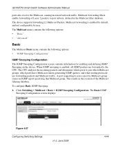
... the creation of Layer 2 packets to port subsets, defined in the Multicast filter database. Click Switching > Multicast > Basic > IGMP Snooping Configuration. The device supports forwarding L2 Multicast Packets. A port requesting to the CPU. Multicast forwarding is enabled, all IGMP packets are forwarding packets and Multicast traffic. The CPU analyzes the incoming packets and determines which ports to join which Multicast groups, which ports have Multicast routers generating IGMP queries, and what routing protocols are forwarded to join a specific Multicast group issues an...
... the creation of Layer 2 packets to port subsets, defined in the Multicast filter database. Click Switching > Multicast > Basic > IGMP Snooping Configuration. The device supports forwarding L2 Multicast Packets. A port requesting to the CPU. Multicast forwarding is enabled, all IGMP packets are forwarding packets and Multicast traffic. The CPU analyzes the incoming packets and determines which ports to join which Multicast groups, which ports have Multicast routers generating IGMP queries, and what routing protocols are forwarded to join a specific Multicast group issues an...
GS7xxTPS User Manual
Page 161
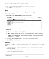
... for defining the QoS queue forwarding types. Indicates the rate that data is averaged over a minimum time increment. Configuring QoS 5-5 v1.0, June 2009 To set to specify the traffic scheduling method. 3. Select to assign WRR weights to specify traffic scheduling based strictly on the queue priority. • WRR - Bandwidth After packets are set the queue settings: 1. Check or uncheck the Restore Defaults box in the interface entry row...
... for defining the QoS queue forwarding types. Indicates the rate that data is averaged over a minimum time increment. Configuring QoS 5-5 v1.0, June 2009 To set to specify the traffic scheduling method. 3. Select to assign WRR weights to specify traffic scheduling based strictly on the queue priority. • WRR - Bandwidth After packets are set the queue settings: 1. Check or uncheck the Restore Defaults box in the interface entry row...
GS7xxTPS User Manual
Page 190
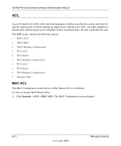
....0, June 2009 Managing Security The ACL menu contains the following options: • "MAC ACL" • "MAC Rules" • "MAC Binding Configuration" • "IPv4 ACL" • "IPv4 Rules" • "IPv4 Binding Configuration" • "IPv6 ACL" • "IPv6 Rules" • "IPv6 Binding Configuration" • "Binding Table" MAC ACL The MAC Configuration screen allows a MAC Based ACL to define classification actions and rules for specific ingress ports. GS700TPS Smart Switch Software Administration Manual ACL Access Control Lists (ACL) allow network managers to be defined...
....0, June 2009 Managing Security The ACL menu contains the following options: • "MAC ACL" • "MAC Rules" • "MAC Binding Configuration" • "IPv4 ACL" • "IPv4 Rules" • "IPv4 Binding Configuration" • "IPv6 ACL" • "IPv6 Rules" • "IPv6 Binding Configuration" • "Binding Table" MAC ACL The MAC Configuration screen allows a MAC Based ACL to define classification actions and rules for specific ingress ports. GS700TPS Smart Switch Software Administration Manual ACL Access Control Lists (ACL) allow network managers to be defined...
GS7xxTPS User Manual
Page 193
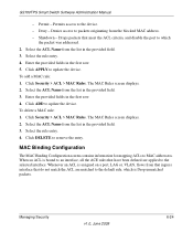
... assigned on a port, LAG or, VLAN, flows from the blocked MAC address. - Select the ACL Name from the list in the provided field. 3. Select the rule entry. 4. Select the rule entry. 4. When an ACL is bound to an interface, all the ACE rules that meet the ACL criteria, and disable the port to the selected interface. Managing Security v1.0, June 2009 6-24 Drops packets that have...
... assigned on a port, LAG or, VLAN, flows from the blocked MAC address. - Select the ACL Name from the list in the provided field. 3. Select the rule entry. 4. Select the rule entry. 4. When an ACL is bound to an interface, all the ACE rules that meet the ACL criteria, and disable the port to the selected interface. Managing Security v1.0, June 2009 6-24 Drops packets that have...
GS7xxTPS User Manual
Page 234
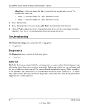
... Smart Switch Software Administration Manual • After Reset - Select the image file to test the quality and characteristics of cable error that is active after the specific unit is reset. The tests use Time Domain Reflectometry (TDR) technology to be tested. Image 2 - See "Reset" for detailed instructions on copper cables. Cables up to a port. Click APPLY to take effect. Cable testing provides information about where errors occurred in the cable...
... Smart Switch Software Administration Manual • After Reset - Select the image file to test the quality and characteristics of cable error that is active after the specific unit is reset. The tests use Time Domain Reflectometry (TDR) technology to be tested. Image 2 - See "Reset" for detailed instructions on copper cables. Cables up to a port. Click APPLY to take effect. Cable testing provides information about where errors occurred in the cable...


