
GS7xxTS-TPS Hardware Installation Guide
Page 7
... management with high-speed links • Link to high-speed servers • Provide 10/100/1000M copper and 100M/1000M fiber connectivity • Connect up to six switches in a stack to support 1G optical module. GS728TS, GS728TPS, GS752TS, and GS752TPS Smart Switch Hardware Installation Guide Overview The NETGEAR GS728TS, GS728TPS, GS752TS, or GS752TPS Smart Switch provides either 24 (GS728TS and GS728TPS) or 48 (GS752TS and GS752TPS) twisted-pair ports that runs on the network requires the Smart Control...
... management with high-speed links • Link to high-speed servers • Provide 10/100/1000M copper and 100M/1000M fiber connectivity • Connect up to six switches in a stack to support 1G optical module. GS728TS, GS728TPS, GS752TS, and GS752TPS Smart Switch Hardware Installation Guide Overview The NETGEAR GS728TS, GS728TPS, GS752TS, or GS752TPS Smart Switch provides either 24 (GS728TS and GS728TPS) or 48 (GS752TS and GS752TPS) twisted-pair ports that runs on the network requires the Smart Control...

GS7xxTS-TPS Hardware Installation Guide
Page 9
..., and GS752TPS Smart Switch Hardware Installation Guide • GS7xxTPS model LEDs: Power and Status LED, FAN status LED, Master LED, LED mode LED and Max PoE LED. • Stack ID LED to display stack member ID (1-6). • Store-and-Forward transmission to remove bad packets from the network. • Full-duplex IEEE 802.3x pause frame flow control. • Active flow control to minimize packet loss and frame drops. • Half-duplex backpressure control. • Per port LEDs and power LED. • Internal open frame power supply. • Standard NETGEAR 7xx series chassis. •...
..., and GS752TPS Smart Switch Hardware Installation Guide • GS7xxTPS model LEDs: Power and Status LED, FAN status LED, Master LED, LED mode LED and Max PoE LED. • Stack ID LED to display stack member ID (1-6). • Store-and-Forward transmission to remove bad packets from the network. • Full-duplex IEEE 802.3x pause frame flow control. • Active flow control to minimize packet loss and frame drops. • Half-duplex backpressure control. • Per port LEDs and power LED. • Internal open frame power supply. • Standard NETGEAR 7xx series chassis. •...

GS7xxTS-TPS Hardware Installation Guide
Page 12
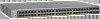
... the line speed and negotiating the duplex mode with the link partner automatically. Each port is capable of which are combo ports. GS728TS Front Panel 10/100/1000M Ethernet Ports Chapter 2. Figure 2 illustrates the front panel of the NETGEAR GS728TS Smart Switch. Up to two SFP ports (port 27 and 28) at a time can be used as stacking ports. Physical Description | 12 Power, Fan, and Stack Master LEDs Stack ID LED Link/Speed/ACT LEDs Combo and Dedicated SFP Ports Factory Defaults Button Reset Button...
... the line speed and negotiating the duplex mode with the link partner automatically. Each port is capable of which are combo ports. GS728TS Front Panel 10/100/1000M Ethernet Ports Chapter 2. Figure 2 illustrates the front panel of the NETGEAR GS728TS Smart Switch. Up to two SFP ports (port 27 and 28) at a time can be used as stacking ports. Physical Description | 12 Power, Fan, and Stack Master LEDs Stack ID LED Link/Speed/ACT LEDs Combo and Dedicated SFP Ports Factory Defaults Button Reset Button...

GS7xxTS-TPS Hardware Installation Guide
Page 15
... port • Power, Fan Status, Stack Master, and Stack ID LEDs Figure 7 illustrates the NETGEAR GS752TS Smart Switch back panel. Power Connector Chapter 2. Up to the factory defaults • Link, Speed, and Activity LEDs for 10/100/1000 Mbps autosensing Gigabit Ethernet switching ports • 2 dedicated SFP ports (port 49 and 50) to support 1G optical module • 2 dedicated SFP ports (port 51 and 52) to support 1G optical module (uplink) or 2.5G stacking (via stacking cable). • Up to two of sensing the line speed...
... port • Power, Fan Status, Stack Master, and Stack ID LEDs Figure 7 illustrates the NETGEAR GS752TS Smart Switch back panel. Power Connector Chapter 2. Up to the factory defaults • Link, Speed, and Activity LEDs for 10/100/1000 Mbps autosensing Gigabit Ethernet switching ports • 2 dedicated SFP ports (port 49 and 50) to support 1G optical module • 2 dedicated SFP ports (port 51 and 52) to support 1G optical module (uplink) or 2.5G stacking (via stacking cable). • Up to two of sensing the line speed...

GS7xxTS-TPS Hardware Installation Guide
Page 16
... LED Select Button Link/Speed/ACT LEDs Combo and Dedicated SFP Ports Factory Defaults Button 10/100/1000M PoE capable Ethernet Ports Reset Button Figure 8. Figure 9 illustrates the NETGEAR GS752TPS Smart Switch back panel. 16 | Chapter 2. GS752TPS Front Panel The front panel contains the following: • 48 RJ-45 connectors for each port. • Power, Fan Status, Stack Master, LED mode, PoE Max, and Stack ID LEDs. Physical Description Figure 8 illustrates the front panel of sensing the line speed and negotiating the duplex mode...
... LED Select Button Link/Speed/ACT LEDs Combo and Dedicated SFP Ports Factory Defaults Button 10/100/1000M PoE capable Ethernet Ports Reset Button Figure 8. Figure 9 illustrates the NETGEAR GS752TPS Smart Switch back panel. 16 | Chapter 2. GS752TPS Front Panel The front panel contains the following: • 48 RJ-45 connectors for each port. • Power, Fan Status, Stack Master, LED mode, PoE Max, and Stack ID LEDs. Physical Description Figure 8 illustrates the front panel of sensing the line speed and negotiating the duplex mode...

GS7xxTS-TPS Hardware Installation Guide
Page 32
... problem by resetting the switch. Switch Integrity If required, verify the integrity of the installation do not resolve the problem, refer to any other networked device. If the device does not support auto negotiation, the switch determines only the speed correctly, and the duplex mode defaults to the Smart Switch Software Administration Manual for information about using the Web interface. GS728TS, GS728TPS, GS752TS, and GS752TPS Smart Switch Hardware Installation Guide Symptom Cause Solution ACT LED is flashing continuously on all connected ports...
... problem by resetting the switch. Switch Integrity If required, verify the integrity of the installation do not resolve the problem, refer to any other networked device. If the device does not support auto negotiation, the switch determines only the speed correctly, and the duplex mode defaults to the Smart Switch Software Administration Manual for information about using the Web interface. GS728TS, GS728TPS, GS752TS, and GS752TPS Smart Switch Hardware Installation Guide Symptom Cause Solution ACT LED is flashing continuously on all connected ports...

GS7xxTS-TPS Hardware Installation Guide
Page 34
... Mbps copper ports or 1G/100M optical module • 2 x SFP (slot) to support 1G optical module. • 2 x SFP (slot) to support 1G optical module (uplink) and 2.5G stacking (via stacking cable). LEDs Per RJ-45 port: Speed/Link/Activity Per SFP port: Speed/Link/Activity Per device: Power, Fan, Stack Master, Stack ID Per device (for GS7xxTPS): LED mode and PoE Max 34 | Appendix : Technical Specifications Jumbo Frame Support (9K) IPv6 Management, Multicast, and QoS Static Routing MLD Snooping DHCP Snooping Protocol and MAC based VLAN DoS and Auto DoS prevention ACLs (MAC, IPv4...
... Mbps copper ports or 1G/100M optical module • 2 x SFP (slot) to support 1G optical module. • 2 x SFP (slot) to support 1G optical module (uplink) and 2.5G stacking (via stacking cable). LEDs Per RJ-45 port: Speed/Link/Activity Per SFP port: Speed/Link/Activity Per device: Power, Fan, Stack Master, Stack ID Per device (for GS7xxTPS): LED mode and PoE Max 34 | Appendix : Technical Specifications Jumbo Frame Support (9K) IPv6 Management, Multicast, and QoS Static Routing MLD Snooping DHCP Snooping Protocol and MAC based VLAN DoS and Auto DoS prevention ACLs (MAC, IPv4...

GS7xxTS-TPS Installation Guide
Page 1
... of a DHCP server, the switch will guide you are using static IP addressing in your network, configure the switch IP address before connecting it to run the utility and view this screen. 2. If you through the installation. Set up the PC with the Smart Control Center Utility 1. Power on the same subnet as the switch. Run the Setup program to configure the switch. 2. Use category 5 (Cat5) unshielded twisted-pair (UTP) cable terminated with an Ethernet adapter and...
... of a DHCP server, the switch will guide you are using static IP addressing in your network, configure the switch IP address before connecting it to run the utility and view this screen. 2. If you through the installation. Set up the PC with the Smart Control Center Utility 1. Power on the same subnet as the switch. Run the Setup program to configure the switch. 2. Use category 5 (Cat5) unshielded twisted-pair (UTP) cable terminated with an Ethernet adapter and...

GS7xxTS-TPS Installation Guide
Page 2
... port status light will display the switch settings main page. In most cases, computers should be sure the switch and computer are some tips for assistance with valid IP addresses. The switch will be lit. • Make sure the network settings of their respective holders. © 2011 NETGEAR, Inc. Troubleshooting Tips Here are configured with configuration procedures. and/or its MAC Address, IP Address, and model number. Click Web Browser Access...
... port status light will display the switch settings main page. In most cases, computers should be sure the switch and computer are some tips for assistance with valid IP addresses. The switch will be lit. • Make sure the network settings of their respective holders. © 2011 NETGEAR, Inc. Troubleshooting Tips Here are configured with configuration procedures. and/or its MAC Address, IP Address, and model number. Click Web Browser Access...

GS7xxTS-TPS Software Admin Manual
Page 7
... Port Mirroring 278 Multiple Port Mirroring 278 Chapter 8 Maintaining the System Reset 280 Device Reboot 280 Factory Default 281 Upload File From Switch 282 TFTP File Upload 282 HTTP File Upload 283 Download File To Switch 284 TFTP File Download 285 HTTP File Download 287 File Management 288 Copy 288 Dual Image Configuration 289 Dual Image Status 291 Troubleshooting 292 Ping 292 Ping IPv6 293 Traceroute 294 Chapter 9 Accessing Help Online Help 296 Support 296 User Guide 297 Registration 298 Appendix A Hardware Specifications...
... Port Mirroring 278 Multiple Port Mirroring 278 Chapter 8 Maintaining the System Reset 280 Device Reboot 280 Factory Default 281 Upload File From Switch 282 TFTP File Upload 282 HTTP File Upload 283 Download File To Switch 284 TFTP File Download 285 HTTP File Download 287 File Management 288 Copy 288 Dual Image Configuration 289 Dual Image Status 291 Troubleshooting 292 Ping 292 Ping IPv6 293 Traceroute 294 Chapter 9 Accessing Help Online Help 296 Support 296 User Guide 297 Registration 298 Appendix A Hardware Specifications...

GS7xxTS-TPS Software Admin Manual
Page 9
... how to manage and monitor IP routing. • Chapter 5, Configuring Quality of Service, describes how to manage the Access Control Lists (ACLs), and how to configure Differentiated Services and Class of information about configuring switch security information such as SNMP, DHCP, PoE, and Green Ethernet. Document Organization The GS728TS, GS728TPS, GS752TS, and GS752TPS Smart Switch Software Administration Manual contains the following chapters: • Chapter 1, Getting Started, contains information about performing the initial system configuration and accessing the user interface...
... how to manage and monitor IP routing. • Chapter 5, Configuring Quality of Service, describes how to manage the Access Control Lists (ACLs), and how to configure Differentiated Services and Class of information about configuring switch security information such as SNMP, DHCP, PoE, and Green Ethernet. Document Organization The GS728TS, GS728TPS, GS752TS, and GS752TPS Smart Switch Software Administration Manual contains the following chapters: • Chapter 1, Getting Started, contains information about performing the initial system configuration and accessing the user interface...

GS7xxTS-TPS Software Admin Manual
Page 138
... access the IGMP Snooping Configuration page, click Switching> Multicast > IGMP Snooping > IGMP Snooping Configuration. 138 Based on the switch. Packets will rarely incur any interest in the IGMP packets as they are identified by all nodes connected to the ports that request the multicast traffic. While nodes will be separated into each of the remaining network segments in full-duplex links. In the case of multicast packets, however, this problem. GS728TS, GS728TPS, GS752TS, and GS752TPS Gigabit Smart Switches IGMP Snooping...
... access the IGMP Snooping Configuration page, click Switching> Multicast > IGMP Snooping > IGMP Snooping Configuration. 138 Based on the switch. Packets will rarely incur any interest in the IGMP packets as they are identified by all nodes connected to the ports that request the multicast traffic. While nodes will be separated into each of the remaining network segments in full-duplex links. In the case of multicast packets, however, this problem. GS728TS, GS728TPS, GS752TS, and GS752TPS Gigabit Smart Switches IGMP Snooping...

GS7xxTS-TPS Software Admin Manual
Page 141
... reset the data on the screen to receive a query on a particular interface before removing it deletes that were created for a particular group on the selected interface(s). Configure the IGMP Snooping values for a particular interface from the list of time you want the switch to wait to the latest value of zero indicates an infinite timeout; no expiration. • Fast Leave Admin Mode. To access the IGMP Snooping Table page, click Switching> Multicast > IGMP Snooping > IGMP Snooping Table...
... reset the data on the screen to receive a query on a particular interface before removing it deletes that were created for a particular group on the selected interface(s). Configure the IGMP Snooping values for a particular interface from the list of time you want the switch to wait to the latest value of zero indicates an infinite timeout; no expiration. • Fast Leave Admin Mode. To access the IGMP Snooping Table page, click Switching> Multicast > IGMP Snooping > IGMP Snooping Table...

GS7xxTS-TPS Software Admin Manual
Page 145
... IGMP protocol version used as source address in the range of the switch. 7. The default value is 125. 6. IGMP Snooping Querier VLAN Configuration Use this page, click Switching> Multicast > IGMP Snooping Querier > Querier VLAN Configuration. 145 In the Query Interval field, specify the time interval in periodic IGMP queries. In the Snooping Querier Address field, specify the IP address to the switch. GS728TS, GS728TPS, GS752TS, and GS752TPS Gigabit Smart Switches To configure IGMP Snooping Querier settings: 1. From the Querier Admin Mode field, enable...
... IGMP protocol version used as source address in the range of the switch. 7. The default value is 125. 6. IGMP Snooping Querier VLAN Configuration Use this page, click Switching> Multicast > IGMP Snooping Querier > Querier VLAN Configuration. 145 In the Query Interval field, specify the time interval in periodic IGMP queries. In the Snooping Querier Address field, specify the IP address to the switch. GS728TS, GS728TPS, GS752TS, and GS752TPS Gigabit Smart Switches To configure IGMP Snooping Querier settings: 1. From the Querier Admin Mode field, enable...

GS7xxTS-TPS Software Admin Manual
Page 149
... access the MLD Snooping Configuration page, click Switching Multicast MLD Snooping Interface Configuration. To configure MLD Snooping settings for a Link Aggregation Group (LAG), click LAGS. 3. Use the Admin Mode menu to specify whether to configure. The default is , no expiration. 149 Select the check box next to the port or LAG to enable or disable MLD snooping on that is 10 seconds. A value of interfaces with the ports to configure. 2. To configure the MLD interface: 1. To configure MLD Snooping settings...
... access the MLD Snooping Configuration page, click Switching Multicast MLD Snooping Interface Configuration. To configure MLD Snooping settings for a Link Aggregation Group (LAG), click LAGS. 3. Use the Admin Mode menu to specify whether to configure. The default is , no expiration. 149 Select the check box next to the port or LAG to enable or disable MLD snooping on that is 10 seconds. A value of interfaces with the ports to configure. 2. To configure the MLD interface: 1. To configure MLD Snooping settings...

GS7xxTS-TPS Software Admin Manual
Page 152
... stack member with the ports to the learned multicast router attached interface list if the interface is active and is applicable only for a physical port, click the unit ID of the switch. To configure multicast router settings for a Link Aggregation Group (LAG), click LAGS. 3. Click Apply to apply the new settings to enable or disable Multicast Router on the interface. Configuration changes take effect immediately 7. To access the Multicast Router VLAN Configuration page, click Switching Multicast MLD Snooping Multicast Router Configuration VLAN...
... stack member with the ports to the learned multicast router attached interface list if the interface is active and is applicable only for a physical port, click the unit ID of the switch. To configure multicast router settings for a Link Aggregation Group (LAG), click LAGS. 3. Click Apply to apply the new settings to enable or disable Multicast Router on the interface. Configuration changes take effect immediately 7. To access the Multicast Router VLAN Configuration page, click Switching Multicast MLD Snooping Multicast Router Configuration VLAN...

GS7xxTS-TPS Software Admin Manual
Page 204
... The number of accounting timeouts to this server. Configuring TACACS+ TACACS+ provides a centralized user management system, while still retaining consistency with an invalid length. Field Description Accounting Server Address Displays the IP address of malformed RADIUS Accounting-Response packets received from this accounting server. Malformed Accounting Responses Displays the number of the supported RADIUS accounting server. GS728TS, GS728TPS, GS752TS, and GS752TPS Gigabit Smart Switches The following table describes RADIUS accounting server statistics...
... The number of accounting timeouts to this server. Configuring TACACS+ TACACS+ provides a centralized user management system, while still retaining consistency with an invalid length. Field Description Accounting Server Address Displays the IP address of malformed RADIUS Accounting-Response packets received from this accounting server. Malformed Accounting Responses Displays the number of the supported RADIUS accounting server. GS728TS, GS728TPS, GS752TS, and GS752TPS Gigabit Smart Switches The following table describes RADIUS accounting server statistics...

GS7xxTS-TPS Software Admin Manual
Page 234
..., which types of routing updates, decide which can identify protocols, source, and destination IP and MAC addresses, and other packet-matching criteria. Next, you create a rule and assign it to reach network resources. You first create an IPv4-based or MAC-based ACL ID. The Security > ACL folder contains links to a LAG. GS728TS, GS728TPS, GS752TS, and GS752TPS Gigabit Smart Switches Configuring Access Control Lists Access Control Lists (ACLs) ensure that only authorized users have access to specific resources while...
..., which types of routing updates, decide which can identify protocols, source, and destination IP and MAC addresses, and other packet-matching criteria. Next, you create a rule and assign it to reach network resources. You first create an IPv4-based or MAC-based ACL ID. The Security > ACL folder contains links to a LAG. GS728TS, GS728TPS, GS752TS, and GS752TPS Gigabit Smart Switches Configuring Access Control Lists Access Control Lists (ACLs) ensure that only authorized users have access to specific resources while...

GS7xxTS-TPS Software Admin Manual
Page 304
... Boot code update DHCP/manual IP Default gateway System name configuration Configuration save/restore Firmware upgrade Restore defaults Dual image support Factory reset Sets Supported 1 1 1 1 1 1 1 (Web and front-panel button) 1 1 Default N/A DHCP enabled/192.168.0.239 192.168.0.254 NULL N/A N/A N/A Enabled N/A System Management Feature Multi-session Web connections SNMPv1/V2c SNMP v3 Time control LLDP/LLDP-MED Logging MIB support Smart Control Center Statistics Sets Supported 16 Max 5 community entries 1 (Local or SNTP) All ports 3 (Memory/Flash/Server) 1 N/A N/A Default Enabled Enabled...
... Boot code update DHCP/manual IP Default gateway System name configuration Configuration save/restore Firmware upgrade Restore defaults Dual image support Factory reset Sets Supported 1 1 1 1 1 1 1 (Web and front-panel button) 1 1 Default N/A DHCP enabled/192.168.0.239 192.168.0.254 NULL N/A N/A N/A Enabled N/A System Management Feature Multi-session Web connections SNMPv1/V2c SNMP v3 Time control LLDP/LLDP-MED Logging MIB support Smart Control Center Statistics Sets Supported 16 Max 5 community entries 1 (Local or SNTP) All ports 3 (Memory/Flash/Server) 1 N/A N/A Default Enabled Enabled...

GS7xxTS-TPS Software Admin Manual
Page 308
... to provide traffic flow control, restrict contents of routing updates, decide which types of traffic are a sequential collection of a packet is , ACL processing occurs at wire speed. If the packet leaves port 1 or port 2, it is stripped of its tag to port 1 and port 2. They can also be used in firewall routers that packets entering these ports are positioned between two parts of the network to control the traffic entering or exiting a specific part of...
... to provide traffic flow control, restrict contents of routing updates, decide which types of traffic are a sequential collection of a packet is , ACL processing occurs at wire speed. If the packet leaves port 1 or port 2, it is stripped of its tag to port 1 and port 2. They can also be used in firewall routers that packets entering these ports are positioned between two parts of the network to control the traffic entering or exiting a specific part of...


