
GS7xxTS-TPS Hardware Installation Guide
Page 1
GS728TS, GS728TPS, GS752TS, and GS752TPS Smart Switch Hardware Installation Guide 350 East Plumeria Drive San Jose, CA 95134 USA January 2012 202-10994-01 v1.0
GS728TS, GS728TPS, GS752TS, and GS752TPS Smart Switch Hardware Installation Guide 350 East Plumeria Drive San Jose, CA 95134 USA January 2012 202-10994-01 v1.0

GS7xxTS-TPS Hardware Installation Guide
Page 2
... registered trademarks of their respective holders. Statement of phone numbers at http://support.netgear.com. GS728TS, GS728TPS, GS752TS, and GS752TPS Smart Switch Hardware Installation Guide ©2012 NETGEAR, Inc. NETGEAR does not assume any means without notice. Phone (US & Canada only): 1-888-NETGEAR Phone (Other Countries): Check the list of Conditions To improve internal design, operational...
... registered trademarks of their respective holders. Statement of phone numbers at http://support.netgear.com. GS728TS, GS728TPS, GS752TS, and GS752TPS Smart Switch Hardware Installation Guide ©2012 NETGEAR, Inc. NETGEAR does not assume any means without notice. Phone (US & Canada only): 1-888-NETGEAR Phone (Other Countries): Check the list of Conditions To improve internal design, operational...

GS7xxTS-TPS Hardware Installation Guide
Page 3
... Contents 10 Chapter 2 Physical Description GS728TS Front-Panel and Back-Panel Configuration 12 GS728TPS Front-Panel and Back-Panel Configuration 13 GS752TS Front-Panel and Back-Panel Configuration 15 GS752TPS Front-Panel and Back-Panel Configuration 16 LED Designations 17 RJ-45 Port LEDs 17 SFP Port LEDs 18 System LEDs 18...
... Contents 10 Chapter 2 Physical Description GS728TS Front-Panel and Back-Panel Configuration 12 GS728TPS Front-Panel and Back-Panel Configuration 13 GS752TS Front-Panel and Back-Panel Configuration 15 GS752TPS Front-Panel and Back-Panel Configuration 16 LED Designations 17 RJ-45 Port LEDs 17 SFP Port LEDs 18 System LEDs 18...

GS7xxTS-TPS Hardware Installation Guide
Page 4
GS728TS, GS728TPS, GS752TS, and GS752TPS Smart Switch Hardware Installation Guide Appendix A Troubleshooting Troubleshooting Chart 31 Additional Troubleshooting Suggestions 32 Network Adapter Cards 32 Configuration 32 Switch Integrity 32 Auto-Negotiation 32 Appendix B Technical Specifications Appendix C Notification of Compliance Index 4 | Contents
GS728TS, GS728TPS, GS752TS, and GS752TPS Smart Switch Hardware Installation Guide Appendix A Troubleshooting Troubleshooting Chart 31 Additional Troubleshooting Suggestions 32 Network Adapter Cards 32 Configuration 32 Switch Integrity 32 Auto-Negotiation 32 Appendix B Technical Specifications Appendix C Notification of Compliance Index 4 | Contents

GS7xxTS-TPS Hardware Installation Guide
Page 5
GS728TS, GS728TPS, GS752TS, and GS752TPS Smart Switch Hardware Installation Guide Contents | 5
GS728TS, GS728TPS, GS752TS, and GS752TPS Smart Switch Hardware Installation Guide Contents | 5

GS7xxTS-TPS Hardware Installation Guide
Page 6
...networks. Introduction | 6 1. This chapter serves as an introduction to install and power on the front panel of your NETGEAR® ProSafeTM GS728TS, GS728TPS, GS752TS, or GS752TPS Smart Switch! There are dedicated 1000M ports, and the last 2 ports can be used for 1000M uplink or 2.5 ...Gbps stacking. The GS728TS, GS728TPS, GS752TS, and GS752TPS Smart Switch Hardware Installation Guide describes how to the Smart Switch and provides the following information: • Overview • Features •...
...networks. Introduction | 6 1. This chapter serves as an introduction to install and power on the front panel of your NETGEAR® ProSafeTM GS728TS, GS728TPS, GS752TS, or GS752TPS Smart Switch! There are dedicated 1000M ports, and the last 2 ports can be used for 1000M uplink or 2.5 ...Gbps stacking. The GS728TS, GS728TPS, GS752TS, and GS752TPS Smart Switch Hardware Installation Guide describes how to the Smart Switch and provides the following information: • Overview • Features •...

GS7xxTS-TPS Hardware Installation Guide
Page 7
...capabilities can create high-speed connections to a server or network backbone. Initial discovery of the switch on a PC. The NETGEAR GS728TS, GS728TPS, GS752TS, or GS752TPS Smart Switch can : • Connect switches to each other switches, or rack mounted in half-duplex or full-duplex ...1000M fiber connectivity • Connect up to create a high-port-capacity solution with a single point of administration The NETGEAR GS728TS, GS728TPS, GS752TS, or GS752TPS Smart Switch also provides the benefit of administrative management with a complete package of which are dedicated 1000M ports, and ...
...capabilities can create high-speed connections to a server or network backbone. Initial discovery of the switch on a PC. The NETGEAR GS728TS, GS728TPS, GS752TS, or GS752TPS Smart Switch can : • Connect switches to each other switches, or rack mounted in half-duplex or full-duplex ...1000M fiber connectivity • Connect up to create a high-port-capacity solution with a single point of administration The NETGEAR GS728TS, GS728TPS, GS752TS, or GS752TPS Smart Switch also provides the benefit of administrative management with a complete package of which are dedicated 1000M ports, and ...

GS7xxTS-TPS Hardware Installation Guide
Page 8
... • Stacking ports • GS728TS/GS728TPS: Port 27 and port 28 can be used as the stacking ports or as uplink ports. • GS752TS/GS752TPS: Port 51 and port 52 can be used as the stacking ports or as uplink ports. • Six 100/1000Mbps SFP slots and two 2.5Gbps... 1-8 support both IEEE802.3 at and af, and port 9-48 support IEEE802.3af. • Autosensing and auto-negotiating capabilities for stacking. • Full NETGEAR Smart Switch functionality. • Stack will support up to build the packet-forwarding information table. The table contains up to a maximum of 6 switches. ...
... • Stacking ports • GS728TS/GS728TPS: Port 27 and port 28 can be used as the stacking ports or as uplink ports. • GS752TS/GS752TPS: Port 51 and port 52 can be used as the stacking ports or as uplink ports. • Six 100/1000Mbps SFP slots and two 2.5Gbps... 1-8 support both IEEE802.3 at and af, and port 9-48 support IEEE802.3af. • Autosensing and auto-negotiating capabilities for stacking. • Full NETGEAR Smart Switch functionality. • Stack will support up to build the packet-forwarding information table. The table contains up to a maximum of 6 switches. ...

GS7xxTS-TPS Hardware Installation Guide
Page 9
GS728TS, GS728TPS, GS752TS, and GS752TPS Smart Switch Hardware Installation Guide • GS7xxTPS model LEDs: Power and Status LED, FAN status LED, Master LED, LED mode LED and Max PoE LED. &#... and frame drops. • Half-duplex backpressure control. • Per port LEDs and power LED. • Internal open frame power supply. • Standard NETGEAR 7xx series chassis. • NETGEAR Green product series power-saving features: • Automatic power consumption adjustment based on the RJ-45 cable length. • Per port automatic power...
GS728TS, GS728TPS, GS752TS, and GS752TPS Smart Switch Hardware Installation Guide • GS7xxTPS model LEDs: Power and Status LED, FAN status LED, Master LED, LED mode LED and Max PoE LED. &#... and frame drops. • Half-duplex backpressure control. • Per port LEDs and power LED. • Internal open frame power supply. • Standard NETGEAR 7xx series chassis. • NETGEAR Green product series power-saving features: • Automatic power consumption adjustment based on the RJ-45 cable length. • Per port automatic power...

GS7xxTS-TPS Hardware Installation Guide
Page 10
...allows the applications running on the Master unit's CPU to control and manage the resources of the GS728TS, GS728TPS, GS752TS, or GS752TPS Smart Switch (the GS752TS is responsible for tabletop installation • Rackmounting kits • Power cord • Installation guide 10 | Chapter... 1. All protocols run in the context of the stack master. Package Contents (GS752TS Shown) Verify that the package contains the following: • GS728TS, GS728TPS, GS752TS, or GS752TPS Smart Switch • Rubber footpads for the entire stack configuration. It updates and synchronizes the ...
...allows the applications running on the Master unit's CPU to control and manage the resources of the GS728TS, GS728TPS, GS752TS, or GS752TPS Smart Switch (the GS752TS is responsible for tabletop installation • Rackmounting kits • Power cord • Installation guide 10 | Chapter... 1. All protocols run in the context of the stack master. Package Contents (GS752TS Shown) Verify that the package contains the following: • GS728TS, GS728TPS, GS752TS, or GS752TPS Smart Switch • Rubber footpads for the entire stack configuration. It updates and synchronizes the ...

GS7xxTS-TPS Hardware Installation Guide
Page 11
Chapter 1. Introduction | 11 GS728TS, GS728TPS, GS752TS, and GS752TPS Smart Switch Hardware Installation Guide • Smart Switch Resource CD with NETGEAR Smart Control Center and User's Manual If any item is missing or damaged, contact the place of purchase immediately.
Chapter 1. Introduction | 11 GS728TS, GS728TPS, GS752TS, and GS752TPS Smart Switch Hardware Installation Guide • Smart Switch Resource CD with NETGEAR Smart Control Center and User's Manual If any item is missing or damaged, contact the place of purchase immediately.

GS7xxTS-TPS Hardware Installation Guide
Page 12
... front panel of sensing the line speed and negotiating the duplex mode with the link partner automatically. Each port is capable of the NETGEAR GS728TS Smart Switch. Physical Description | 12 Up to two SFP ports (port 27 and 28) at a time can be used as ...include: • GS728TS Front-Panel and Back-Panel Configuration • GS728TPS Front-Panel and Back-Panel Configuration • GS752TS Front-Panel and Back-Panel Configuration • GS752TPS Front-Panel and Back-Panel Configuration • LED Designations • Device Hardware Interfaces GS728TS Front-Panel and Back-Panel ...
... front panel of sensing the line speed and negotiating the duplex mode with the link partner automatically. Each port is capable of the NETGEAR GS728TS Smart Switch. Physical Description | 12 Up to two SFP ports (port 27 and 28) at a time can be used as ...include: • GS728TS Front-Panel and Back-Panel Configuration • GS728TPS Front-Panel and Back-Panel Configuration • GS752TS Front-Panel and Back-Panel Configuration • GS752TPS Front-Panel and Back-Panel Configuration • LED Designations • Device Hardware Interfaces GS728TS Front-Panel and Back-Panel ...

GS7xxTS-TPS Hardware Installation Guide
Page 13
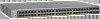
GS728TS, GS728TPS, GS752TS, and GS752TPS Smart Switch Hardware Installation Guide The front panel contains the following: • 24 RJ-45 connectors for each port. • Power, Fan Status, Stack Master, ...-Panel and Back-Panel Configuration The GS728TPS Smart Switch has 24 10/100/1000 Mbps PoE capable copper ports and 6 SFP fiber ports, 2 of the NETGEAR GS728TPS Smart Switch. Physical Description | 13 Figure 3 illustrates the...
GS728TS, GS728TPS, GS752TS, and GS752TPS Smart Switch Hardware Installation Guide The front panel contains the following: • 24 RJ-45 connectors for each port. • Power, Fan Status, Stack Master, ...-Panel and Back-Panel Configuration The GS728TPS Smart Switch has 24 10/100/1000 Mbps PoE capable copper ports and 6 SFP fiber ports, 2 of the NETGEAR GS728TPS Smart Switch. Physical Description | 13 Figure 3 illustrates the...

GS7xxTS-TPS Hardware Installation Guide
Page 14
Figure 5. GS728TPS Back Panel The back panel contains a power connector. 14 | Chapter 2. Physical Description Power Connector GS728TS, GS728TPS, GS752TS, and GS752TPS Smart Switch Hardware Installation Guide Power, Fan, LED mode, PoE Max, and Stack Master LEDs Stack ID LED Link/Speed/ACT LEDs Combo and Dedicated ...; Link, Speed, and Activity LEDs for each port. • Power, Fan Status, Stack Master, LED mode, PoE Max, and Stack ID LEDs. Figure 5 illustrates the NETGEAR GS728TPS Smart Switch back panel.
Figure 5. GS728TPS Back Panel The back panel contains a power connector. 14 | Chapter 2. Physical Description Power Connector GS728TS, GS728TPS, GS752TS, and GS752TPS Smart Switch Hardware Installation Guide Power, Fan, LED mode, PoE Max, and Stack Master LEDs Stack ID LED Link/Speed/ACT LEDs Combo and Dedicated ...; Link, Speed, and Activity LEDs for each port. • Power, Fan Status, Stack Master, LED mode, PoE Max, and Stack ID LEDs. Figure 5 illustrates the NETGEAR GS728TPS Smart Switch back panel.

GS7xxTS-TPS Hardware Installation Guide
Page 15
...and 52) at a time can alternatively be used as stacking ports. Power Connector Chapter 2. Each port is capable of the NETGEAR GS752TS Smart Switch. Power, Fan, and Stack Master LEDs Stack ID LED Link/Speed/ACT LEDs Combo and Dedicated SFP Ports Factory Defaults...the duplex mode with the link partner automatically. Figure 7. GS752TS Back Panel The back panel contains a power connector. GS728TS, GS728TPS, GS752TS, and GS752TPS Smart Switch Hardware Installation Guide GS752TS Front-Panel and Back-Panel Configuration The GS752TS Smart Switch has 48 10/100/1000 Mbps copper ports ...
...and 52) at a time can alternatively be used as stacking ports. Power Connector Chapter 2. Each port is capable of the NETGEAR GS752TS Smart Switch. Power, Fan, and Stack Master LEDs Stack ID LED Link/Speed/ACT LEDs Combo and Dedicated SFP Ports Factory Defaults...the duplex mode with the link partner automatically. Figure 7. GS752TS Back Panel The back panel contains a power connector. GS728TS, GS728TPS, GS752TS, and GS752TPS Smart Switch Hardware Installation Guide GS752TS Front-Panel and Back-Panel Configuration The GS752TS Smart Switch has 48 10/100/1000 Mbps copper ports ...

GS7xxTS-TPS Hardware Installation Guide
Page 16
Physical Description GS728TS, GS728TPS, GS752TS, and GS752TPS Smart Switch Hardware Installation Guide GS752TPS Front-Panel and Back-Panel Configuration The GS752TPS Smart Switch has 48 10/100/1000 Mbps PoE capable copper ports and 6 SFP fiber ports, 2 of the NETGEAR GS752TPS Smart Switch. Power, Fan, LED mode, PoE Max, and ... for each port. • Power, Fan Status, Stack Master, LED mode, PoE Max, and Stack ID LEDs. Figure 9 illustrates the NETGEAR GS752TPS Smart Switch back panel. 16 | Chapter 2. Each port is capable of the port LEDs with the link partner automatically.
Physical Description GS728TS, GS728TPS, GS752TS, and GS752TPS Smart Switch Hardware Installation Guide GS752TPS Front-Panel and Back-Panel Configuration The GS752TPS Smart Switch has 48 10/100/1000 Mbps PoE capable copper ports and 6 SFP fiber ports, 2 of the NETGEAR GS752TPS Smart Switch. Power, Fan, LED mode, PoE Max, and ... for each port. • Power, Fan Status, Stack Master, LED mode, PoE Max, and Stack ID LEDs. Figure 9 illustrates the NETGEAR GS752TPS Smart Switch back panel. 16 | Chapter 2. Each port is capable of the port LEDs with the link partner automatically.

GS7xxTS-TPS Hardware Installation Guide
Page 17
GS728TS, GS728TPS, GS752TS, and GS752TPS Smart Switch Hardware Installation Guide Figure 9. The port is changed to fiber, the Ethernet LED will change to that port: - PoE Mode: PoE Status LED &#... or receiving packets at 1000 Mbps. • Solid Yellow - PoE current exceeds the PD's classification. - A valid 10/100 Mbps link is established. • Blinking Green - GS752TPS Back Panel The back panel contains a power connector. Physical Description | 17 LED Designation Ethernet Mode: SPD/Link/ACT LED • Off- LED Designations Power Connector...
GS728TS, GS728TPS, GS752TS, and GS752TPS Smart Switch Hardware Installation Guide Figure 9. The port is changed to fiber, the Ethernet LED will change to that port: - PoE Mode: PoE Status LED &#... or receiving packets at 1000 Mbps. • Solid Yellow - PoE current exceeds the PD's classification. - A valid 10/100 Mbps link is established. • Blinking Green - GS752TPS Back Panel The back panel contains a power connector. Physical Description | 17 LED Designation Ethernet Mode: SPD/Link/ACT LED • Off- LED Designations Power Connector...
GS7xxTS-TPS Hardware Installation Guide
Page 18
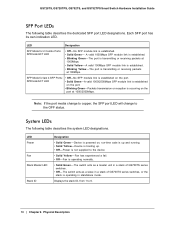
... up . • Off - Each SFP port has its own indication LED. No SFP module link is booting up and running. • Solid Yellow - GS728TS, GS728TPS, GS752TS, and GS752TPS Smart Switch Hardware Installation Guide SFP Port LEDs The following table describes the system LED designations. Device is established. • Solid Green -
... up . • Off - Each SFP port has its own indication LED. No SFP module link is booting up and running. • Solid Yellow - GS728TS, GS728TPS, GS752TS, and GS752TPS Smart Switch Hardware Installation Guide SFP Port LEDs The following table describes the system LED designations. Device is established. • Solid Green -

GS7xxTS-TPS Hardware Installation Guide
Page 19
... and 28 or 51 and 52) can alternatively be used to support 1G optical module (uplink) or 2.5G stacking (via stacking cable). GS728TS, GS728TPS, GS752TS, and GS752TPS Smart Switch Hardware Installation Guide LED Max PoE LED LED Mode LED Designation • Solid Green -Less than 7W of the attached device. This technology...
... and 28 or 51 and 52) can alternatively be used to support 1G optical module (uplink) or 2.5G stacking (via stacking cable). GS728TS, GS728TPS, GS752TS, and GS752TPS Smart Switch Hardware Installation Guide LED Max PoE LED LED Mode LED Designation • Solid Green -Less than 7W of the attached device. This technology...
GS7xxTS-TPS Hardware Installation Guide
Page 20
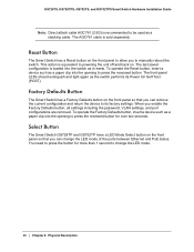
... resets. To operate the Reset button, insert a device such as the switch performs its factory settings. Select Button The Smart Switch GS728TP and GS752TP have a LED Mode Select button on . You need to its Power On Self Test (POST). Reset Button The Smart Switch has a Reset...panel so that you can remove the current configuration and return the device to press the button for over two seconds. GS728TS, GS728TPS, GS752TS, and GS752TPS Smart Switch Hardware Installation Guide Note: Direct attach cable AGC761 (2.5G) is sold separately. Factory Defaults Button The Smart Switch has a ...
... resets. To operate the Reset button, insert a device such as the switch performs its factory settings. Select Button The Smart Switch GS728TP and GS752TP have a LED Mode Select button on . You need to its Power On Self Test (POST). Reset Button The Smart Switch has a Reset...panel so that you can remove the current configuration and return the device to press the button for over two seconds. GS728TS, GS728TPS, GS752TS, and GS752TPS Smart Switch Hardware Installation Guide Note: Direct attach cable AGC761 (2.5G) is sold separately. Factory Defaults Button The Smart Switch has a ...