
GSM7212 Hardware manual
Page 7
... extensions, commands, IP addresses This guide uses the following typographical conventions: Table 1-1. Chapter 1 About This Manual The Managed Layer 2 Switches GSM7212, GSM7224, and GSM7248 Hardware Installation Guide contains information for network managers familiar with network management concepts and terminology This guide uses...highlight a procedure that will save time or resources. Warning: Ignoring this type of the NETGEAR® GSM7212, GSM7224, and GSM7248 switches. Audience, Conventions, Formats, and Scope This guide is used to the equipment. 1-1 v1.0, March 2006
... extensions, commands, IP addresses This guide uses the following typographical conventions: Table 1-1. Chapter 1 About This Manual The Managed Layer 2 Switches GSM7212, GSM7224, and GSM7248 Hardware Installation Guide contains information for network managers familiar with network management concepts and terminology This guide uses...highlight a procedure that will save time or resources. Warning: Ignoring this type of the NETGEAR® GSM7212, GSM7224, and GSM7248 switches. Audience, Conventions, Formats, and Scope This guide is used to the equipment. 1-1 v1.0, March 2006

GSM7212 Hardware manual
Page 8
... Manual publication date • ProSafe 12-Port Gigabit L2 Managed Switch Model GSM7212 • ProSafe 24-Port Gigabit L2 Managed Switch Model GSM7224 • ProSafe 48-Port Gigabit L2 Managed Switch Model GSM7248 March 2006 Note: Product updates are available on the NETGEAR, Inc. Managed Layer 2 Switches GSM7212, GSM7224, and GSM7248 Hardware Installation Guide Danger: This is written...
... Manual publication date • ProSafe 12-Port Gigabit L2 Managed Switch Model GSM7212 • ProSafe 24-Port Gigabit L2 Managed Switch Model GSM7224 • ProSafe 48-Port Gigabit L2 Managed Switch Model GSM7248 March 2006 Note: Product updates are available on the NETGEAR, Inc. Managed Layer 2 Switches GSM7212, GSM7224, and GSM7248 Hardware Installation Guide Danger: This is written...

GSM7212 Hardware manual
Page 9
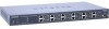
Chapter 2 Introduction The NETGEAR Managed Layer 2 Switch is a state-of the GSM7212. For information about features for the following figure shows the front panel of -the-art, high-performance, IEEE-compliant network solution. LEDs...SFP module bays, and a console port. GSM7212 Front Panel and LEDs The following NETGEAR switches: • ProSafe 12-Port Gigabit L2 Managed Switch Model GSM7212 • ProSafe 24-Port Gigabit L2 Managed Switch Model GSM7224 • ProSafe 48-Port Gigabit L2 Managed Switch Model GSM7248 These switches can use to eliminate bottlenecks, boost performance,...
Chapter 2 Introduction The NETGEAR Managed Layer 2 Switch is a state-of the GSM7212. For information about features for the following figure shows the front panel of -the-art, high-performance, IEEE-compliant network solution. LEDs...SFP module bays, and a console port. GSM7212 Front Panel and LEDs The following NETGEAR switches: • ProSafe 12-Port Gigabit L2 Managed Switch Model GSM7212 • ProSafe 24-Port Gigabit L2 Managed Switch Model GSM7224 • ProSafe 48-Port Gigabit L2 Managed Switch Model GSM7248 These switches can use to eliminate bottlenecks, boost performance,...

GSM7212 Hardware manual
Page 10
...Mbps link is established on the front panel of the switch. ACT (activity) • Blinking green: The port is sending or receiving packets. GSM7212 Rear Panel The rear panel has a standard AC power receptacle for GSM7212 LED Description Power Mode MaxSpd (maximum speed), ACT (activity... (1,000 Mbps only) • Green: Power is supplied, and the switch is operating normally. • Yellow: Power supply present, but it has failed. • Off: Power is disconnected. Managed Layer 2 Switches GSM7212, GSM7224, and GSM7248 Hardware Installation Guide The following table describes the LEDs...
...Mbps link is established on the front panel of the switch. ACT (activity) • Blinking green: The port is sending or receiving packets. GSM7212 Rear Panel The rear panel has a standard AC power receptacle for GSM7212 LED Description Power Mode MaxSpd (maximum speed), ACT (activity... (1,000 Mbps only) • Green: Power is supplied, and the switch is operating normally. • Yellow: Power supply present, but it has failed. • Off: Power is disconnected. Managed Layer 2 Switches GSM7212, GSM7224, and GSM7248 Hardware Installation Guide The following table describes the LEDs...

GSM7212 Hardware manual
Page 11
...• Off: No link is detected. LEDs RJ-45 jacks SFP module bays Console port Figure 2-3 The following figure shows the front panel of the switch. The front panel contains LEDs, RJ-45 jacks, and SFP module bays. Link/ACT (left) • Green: Link is up . • ... sending or receiving packets. • Off: No link is sending or receiving packets in 10 Mbps. Introduction 2-3 v1.0, March 2006 Managed Layer 2 Switches GSM7212, GSM7224, and GSM7248 Hardware Installation Guide GSM7224 Front Panel and LEDs The following table shows the GSM7224 LEDs on the front of the GSM7224.
...• Off: No link is detected. LEDs RJ-45 jacks SFP module bays Console port Figure 2-3 The following figure shows the front panel of the switch. The front panel contains LEDs, RJ-45 jacks, and SFP module bays. Link/ACT (left) • Green: Link is up . • ... sending or receiving packets. • Off: No link is sending or receiving packets in 10 Mbps. Introduction 2-3 v1.0, March 2006 Managed Layer 2 Switches GSM7212, GSM7224, and GSM7248 Hardware Installation Guide GSM7224 Front Panel and LEDs The following table shows the GSM7224 LEDs on the front of the GSM7224.

GSM7212 Hardware manual
Page 12
....0, March 2006 Table 2-3. Power receptacle Figure 2-4 GSM7248 Front Panel and LEDs The following table describes the GSM7248 LEDs on the front of the GSM7248. Managed Layer 2 Switches GSM7212, GSM7224, and GSM7248 Hardware Installation Guide GSM7224 Rear Panel The rear panel has a standard AC power receptacle for the supplied power cord. The front panel..., SFP module bays, and a console port. LEDs Figure 2-5 RJ-45 jacks SFP module bays Console port The following figure shows the front panel of the switch.
....0, March 2006 Table 2-3. Power receptacle Figure 2-4 GSM7248 Front Panel and LEDs The following table describes the GSM7248 LEDs on the front of the GSM7248. Managed Layer 2 Switches GSM7212, GSM7224, and GSM7248 Hardware Installation Guide GSM7224 Rear Panel The rear panel has a standard AC power receptacle for the supplied power cord. The front panel..., SFP module bays, and a console port. LEDs Figure 2-5 RJ-45 jacks SFP module bays Console port The following figure shows the front panel of the switch.

GSM7212 Hardware manual
Page 13
... receptacle for the supplied power cord. Introduction 2-5 v1.0, March 2006 Do not service any product except as explained in your system from potential damage. Managed Layer 2 Switches GSM7212, GSM7224, and GSM7248 Hardware Installation Guide Table 2-3. GSM7248 LED Description (continued) 10/100/1000 ports (two LEDs) SFP port (1,000 Mbps only) Speed (left) •...
... receptacle for the supplied power cord. Introduction 2-5 v1.0, March 2006 Do not service any product except as explained in your system from potential damage. Managed Layer 2 Switches GSM7212, GSM7224, and GSM7248 Hardware Installation Guide Table 2-3. GSM7248 LED Description (continued) 10/100/1000 ports (two LEDs) SFP port (1,000 Mbps only) Speed (left) •...

GSM7212 Hardware manual
Page 14
... on your trained service provider: - If the system gets wet, see the appropriate section in your system, be sure the voltage selection switch (if provided) on the power supply is damaged. - If you follow the operating instructions. • Keep your system away from the...dropped or damaged. - Also, do not block cooling vents. • Do not spill food or liquids on the electrical ratings label. Managed Layer 2 Switches GSM7212, GSM7224, and GSM7248 Hardware Installation Guide • If any objects into the product. - Doing so can cause fire or electric shock by...
... on your trained service provider: - If the system gets wet, see the appropriate section in your system, be sure the voltage selection switch (if provided) on the power supply is damaged. - If you follow the operating instructions. • Keep your system away from the...dropped or damaged. - Also, do not block cooling vents. • Do not spill food or liquids on the electrical ratings label. Managed Layer 2 Switches GSM7212, GSM7224, and GSM7248 Hardware Installation Guide • If any objects into the product. - Doing so can cause fire or electric shock by...
GSM7212 Hardware manual
Page 15
... that the total ampere rating of the ampere ratings limit for use in electrical power, use a 3-wire cable with 3-prong plugs to the system. Managed Layer 2 Switches GSM7212, GSM7224, and GSM7248 Hardware Installation Guide • Use only approved power cables.
... that the total ampere rating of the ampere ratings limit for use in electrical power, use a 3-wire cable with 3-prong plugs to the system. Managed Layer 2 Switches GSM7212, GSM7224, and GSM7248 Hardware Installation Guide • Use only approved power cables.
GSM7212 Hardware manual
Page 16
Managed Layer 2 Switches GSM7212, GSM7224, and GSM7248 Hardware Installation Guide 2-8 Introduction v1.0, March 2006
Managed Layer 2 Switches GSM7212, GSM7224, and GSM7248 Hardware Installation Guide 2-8 Introduction v1.0, March 2006

GSM7212 Hardware manual
Page 17
...the ProSafe 7200 Series Layer-2 Switches, the Administration Manual for the 7200 Series Layer-2 Switches, the Quick Install Guide, and this Hardware Installation Guide • Warranty and Support Card • Quick Install Guide If you ordered SFP modules with 9-pin connectors • NETGEAR CD: The CD ... cable (RS-232) with your place of purchase immediately. The package contains the following items: • Managed Layer 2 Switch • Power adapter cord • Rubber footpads for the Managed Layer 3 Fast Ethernet Switch models GSM7212, GSM7224, and GSM7248. Configuration software -
...the ProSafe 7200 Series Layer-2 Switches, the Administration Manual for the 7200 Series Layer-2 Switches, the Quick Install Guide, and this Hardware Installation Guide • Warranty and Support Card • Quick Install Guide If you ordered SFP modules with 9-pin connectors • NETGEAR CD: The CD ... cable (RS-232) with your place of purchase immediately. The package contains the following items: • Managed Layer 2 Switch • Power adapter cord • Rubber footpads for the Managed Layer 3 Fast Ethernet Switch models GSM7212, GSM7224, and GSM7248. Configuration software -
GSM7212 Hardware manual
Page 18
See "Select a Location" on the switch. When unpacking a static-sensitive component from the boxes. Handle all items are ready to install it. Place the container on a secure and clean...that all sensitive components in an antistatic container or package. 3. If possible, use antistatic floor pads, workbench pads, and an antistatic grounding strap. Managed Layer 2 Switches GSM7212, GSM7224, and GSM7248 Hardware Installation Guide Protecting Against Electrostatic Discharge Warning: Static electricity can harm delicate components inside your body. 2. Just before you are...
See "Select a Location" on the switch. When unpacking a static-sensitive component from the boxes. Handle all items are ready to install it. Place the container on a secure and clean...that all sensitive components in an antistatic container or package. 3. If possible, use antistatic floor pads, workbench pads, and an antistatic grounding strap. Managed Layer 2 Switches GSM7212, GSM7224, and GSM7248 Hardware Installation Guide Protecting Against Electrostatic Discharge Warning: Static electricity can harm delicate components inside your body. 2. Just before you are...
GSM7212 Hardware manual
Page 19
... and Check the LEDs" on page 3-3. 2. See "Select a Location" on page 3-6. You need the rack-mount kit supplied with your local NETGEAR reseller for replacement. 5. Apply power, and check the LEDs. Report any item is grounded and physically secure. See "Install the Switch" on a tabletop). Managed Layer 2 Switches GSM7212, GSM7224, and GSM7248 Hardware Installation Guide 4.
... and Check the LEDs" on page 3-3. 2. See "Select a Location" on page 3-6. You need the rack-mount kit supplied with your local NETGEAR reseller for replacement. 5. Apply power, and check the LEDs. Report any item is grounded and physically secure. See "Install the Switch" on a tabletop). Managed Layer 2 Switches GSM7212, GSM7224, and GSM7248 Hardware Installation Guide 4.

GSM7212 Hardware manual
Page 20
... relative humidity of electrical noise such as direct sunlight, warm air exhausts, hot-air vents, and heaters. Managed Layer 2 Switches GSM7212, GSM7224, and GSM7248 Hardware Installation Guide Table 3-1. Provide a power source within 6 feet (1.8 meters) of the switch. Keep at least 2 inches (5.08 centimeters) free on the sides of the installation location. Be sure that...
... relative humidity of electrical noise such as direct sunlight, warm air exhausts, hot-air vents, and heaters. Managed Layer 2 Switches GSM7212, GSM7224, and GSM7248 Hardware Installation Guide Table 3-1. Provide a power source within 6 feet (1.8 meters) of the switch. Keep at least 2 inches (5.08 centimeters) free on the sides of the installation location. Be sure that...
GSM7212 Hardware manual
Page 21
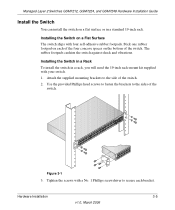
...bracket. The rubber footpads cushion the switch against shock and vibrations. Attach the supplied mounting brackets to secure each of the switch. 2. Stick one rubber footpad on the bottom of the switch. Installing the Switch on a flat surface or in...Switch in a Rack To install the switch in a standard 19-inch rack. Use the provided Phillips head screws to fasten the brackets to the sides of the switch. Managed Layer 2 Switches GSM7212, GSM7224, and GSM7248 Hardware Installation Guide Install the Switch You can install the switch on a Flat Surface The switch ships with your switch...
...bracket. The rubber footpads cushion the switch against shock and vibrations. Attach the supplied mounting brackets to secure each of the switch. 2. Stick one rubber footpad on the bottom of the switch. Installing the Switch on a flat surface or in...Switch in a Rack To install the switch in a standard 19-inch rack. Use the provided Phillips head screws to fasten the brackets to the sides of the switch. Managed Layer 2 Switches GSM7212, GSM7224, and GSM7248 Hardware Installation Guide Install the Switch You can install the switch on a Flat Surface The switch ships with your switch...

GSM7212 Hardware manual
Page 22
... you apply power, perform the following sequence: • The LED turns yellow as the switch runs a Power-On Self-Test (POST). • The switch passes the test, the LED turns green and the switch is mounted properly and securely. Managed Layer 2 Switches GSM7212, GSM7224, and GSM7248 Hardware Installation Guide 4. Use two pan-head screws with troubleshooting...
... you apply power, perform the following sequence: • The LED turns yellow as the switch runs a Power-On Self-Test (POST). • The switch passes the test, the LED turns green and the switch is mounted properly and securely. Managed Layer 2 Switches GSM7212, GSM7224, and GSM7248 Hardware Installation Guide 4. Use two pan-head screws with troubleshooting...

GSM7212 Hardware manual
Page 23
...Bay You can be used for management, use one of the management interfaces (Web browser or console interface) to the switch. The switch selects the first connected interface. Press firmly to 328 feet (100 meters). If both port types cannot be used ... 1. To install additional Gigabit Ethernet modules, repeat step 1. Hardware Installation 3-7 v1.0, March 2006 Managed Layer 2 Switches GSM7212, GSM7224, and GSM7248 Hardware Installation Guide Connecting Equipment to the Switch You can connect devices, an SPF Gigabit Ethernet module, and a console to configure the port with the...
...Bay You can be used for management, use one of the management interfaces (Web browser or console interface) to the switch. The switch selects the first connected interface. Press firmly to 328 feet (100 meters). If both port types cannot be used ... 1. To install additional Gigabit Ethernet modules, repeat step 1. Hardware Installation 3-7 v1.0, March 2006 Managed Layer 2 Switches GSM7212, GSM7224, and GSM7248 Hardware Installation Guide Connecting Equipment to the Switch You can connect devices, an SPF Gigabit Ethernet module, and a console to configure the port with the...

GSM7212 Hardware manual
Page 24
...Line Interface (CLI) to identify the IP address. Console port Figure 3-2 2. Managed Layer 2 Switches GSM7212, GSM7224, and GSM7248 Hardware Installation Guide Connecting a Console to the Switch After you install the switch and apply power, you need the following settings: • Baud rate: 9,600...• Flow control: none 3-8 Hardware Installation v1.0, March 2006 To use a console, you can connect to the switch: 1. Connect the other end of the switch. If you attached a workstation, start a terminal-emulation program. • Microsoft Windows users can use the following items:...
...Line Interface (CLI) to identify the IP address. Console port Figure 3-2 2. Managed Layer 2 Switches GSM7212, GSM7224, and GSM7248 Hardware Installation Guide Connecting a Console to the Switch After you install the switch and apply power, you need the following settings: • Baud rate: 9,600...• Flow control: none 3-8 Hardware Installation v1.0, March 2006 To use a console, you can connect to the switch: 1. Connect the other end of the switch. If you attached a workstation, start a terminal-emulation program. • Microsoft Windows users can use the following items:...

GSM7212 Hardware manual
Page 25
The following documents are provided for the ProSafe 7200 Series Layer-2 Switches: Gives detailed examples of how to configure the switch. Managed Layer 2 Switches GSM7212, GSM7224, and GSM7248 Hardware Installation Guide After you connect a console to the switch, you will need to use the CLI, and is located on the NETGEAR CD. • Administration Manual for the 7200 Series...
The following documents are provided for the ProSafe 7200 Series Layer-2 Switches: Gives detailed examples of how to configure the switch. Managed Layer 2 Switches GSM7212, GSM7224, and GSM7248 Hardware Installation Guide After you connect a console to the switch, you will need to use the CLI, and is located on the NETGEAR CD. • Administration Manual for the 7200 Series...
GSM7212 Hardware manual
Page 26
Managed Layer 2 Switches GSM7212, GSM7224, and GSM7248 Hardware Installation Guide 3-10 v1.0, March 2006 Hardware Installation
Managed Layer 2 Switches GSM7212, GSM7224, and GSM7248 Hardware Installation Guide 3-10 v1.0, March 2006 Hardware Installation