
Product Data Sheet
Page 1
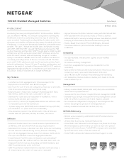
... the entire AV over IP systems of up to support hundreds of AV over -IP configuration Industry leading warranty • NETGEAR M4500 series is covered under NETGEAR ProSAFE Limited Lifetime Hardware Warranty* • 90 days of Technical Support via phone and email, Lifetime Technical Support through online... and scalability of Ethernet to 96 I/Os using a single switch and Layer-2 Multicast IGMP. A 10G to 100G solution • The M4500-32C offers 32-port QSFP28 preconfigured for 100G and can support 10G and 25G For Pro AV installations • Installers opting to design AV over...
... the entire AV over IP systems of up to support hundreds of AV over -IP configuration Industry leading warranty • NETGEAR M4500 series is covered under NETGEAR ProSAFE Limited Lifetime Hardware Warranty* • 90 days of Technical Support via phone and email, Lifetime Technical Support through online... and scalability of Ethernet to 96 I/Os using a single switch and Layer-2 Multicast IGMP. A 10G to 100G solution • The M4500-32C offers 32-port QSFP28 preconfigured for 100G and can support 10G and 25G For Pro AV installations • Installers opting to design AV over...
Product Data Sheet
Page 4
...µs @100G; The trend of moving matrix switching into the Ethernet network is already preconfigured out of switches has come to use the M4500-32C switch to aggregate the edge switches for a complete set up in a redundant spine and leaf architecture • 2 power supply units (...simplify system architectures with VRRP, OSPF, BGP, VRF-Lite and PIM. Removing the need for 90 days (Remote diagnostics performed by a NETGEAR ProSAFE® Limited Lifetime Hardware Warranty* • Lifetime Next Business Day Hardware Replacement • ProSUPPORT 24x7 Advanced Technical Support via chat...
...µs @100G; The trend of moving matrix switching into the Ethernet network is already preconfigured out of switches has come to use the M4500-32C switch to aggregate the edge switches for a complete set up in a redundant spine and leaf architecture • 2 power supply units (...simplify system architectures with VRRP, OSPF, BGP, VRF-Lite and PIM. Removing the need for 90 days (Remote diagnostics performed by a NETGEAR ProSAFE® Limited Lifetime Hardware Warranty* • Lifetime Next Business Day Hardware Replacement • ProSUPPORT 24x7 Advanced Technical Support via chat...
Product Data Sheet
Page 27
...) No No No No No Yes Yes Yes No No Yes MIBs can be dowloaded here: http://www.netgear.com/support/product/m4500-32c.aspx Speed, Link, Activity Power, System, PSU 1, PSU 2, Fan Width: 17.32 inches (44 ... MIBs Base Package MIBs LEDs Per port Per device Physical Specifications Dimensions M4500-32C M4500-48XF8C Weight M4500-32C M4500-48XF8C Power Consumption Worst case, all ports used, line-rate traffic M4500-32C M4500-48XF8C Environmental Specifications Operating: Temperature Humidity Altitude Storage: Temperature Humidity Altitude Max...
...) No No No No No Yes Yes Yes No No Yes MIBs can be dowloaded here: http://www.netgear.com/support/product/m4500-32c.aspx Speed, Link, Activity Power, System, PSU 1, PSU 2, Fan Width: 17.32 inches (44 ... MIBs Base Package MIBs LEDs Per port Per device Physical Specifications Dimensions M4500-32C M4500-48XF8C Weight M4500-32C M4500-48XF8C Power Consumption Worst case, all ports used, line-rate traffic M4500-32C M4500-48XF8C Environmental Specifications Operating: Temperature Humidity Altitude Storage: Temperature Humidity Altitude Max...

Product Data Sheet
Page 29
... 90 days after purchase Included, lifetime Included, lifetime All models Remote Installation Setup and Configuration Service Contract (2-hour planned appointment) M4500-32C M4500-48XF8C OnCall 24x7 1-year CAT 4 OnCall 24x7 3-year CAT 4 OnCall 24x7 5-year CAT 4 CSM4532-100NAS CSM4532-100EUS CSM4532-...is subject to change without notice. © 2020 NETGEAR, Inc. NETGEAR, the NETGEAR Logo and ProSAFE are for identification purposes only and may be trademarks of NETGEAR, Inc. Information is valid only if purchased from a NETGEAR authorized reseller, and covers unmodified hardware, fans and ...
... 90 days after purchase Included, lifetime Included, lifetime All models Remote Installation Setup and Configuration Service Contract (2-hour planned appointment) M4500-32C M4500-48XF8C OnCall 24x7 1-year CAT 4 OnCall 24x7 3-year CAT 4 OnCall 24x7 5-year CAT 4 CSM4532-100NAS CSM4532-100EUS CSM4532-...is subject to change without notice. © 2020 NETGEAR, Inc. NETGEAR, the NETGEAR Logo and ProSAFE are for identification purposes only and may be trademarks of NETGEAR, Inc. Information is valid only if purchased from a NETGEAR authorized reseller, and covers unmodified hardware, fans and ...

Installation Guide
Page 1
... 4. At the password prompt, do not need to as prompted by visiting netgear.com/support/download/. You do not type a password but press Enter. Installation Guide M4500 Intelligent Fully Managed Switches M4500-32C and M4500-48XF8C 1. Install the switch using the following information: • If the ... LED remains solid yellow, the POST failed. The Power LED lights solid yellow while the switch conducts a power-on models M4500-48XF8C and M4500-32C are preconfigured for initial configuration and assign a static or dynamic IP address to the switch, connect a computer or VT100/ANSI...
... 4. At the password prompt, do not need to as prompted by visiting netgear.com/support/download/. You do not type a password but press Enter. Installation Guide M4500 Intelligent Fully Managed Switches M4500-32C and M4500-48XF8C 1. Install the switch using the following information: • If the ... LED remains solid yellow, the POST failed. The Power LED lights solid yellow while the switch conducts a power-on models M4500-48XF8C and M4500-32C are preconfigured for initial configuration and assign a static or dynamic IP address to the switch, connect a computer or VT100/ANSI...
Hardware Installation Guide
Page 5
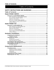
... Connection 11 Fan tray of model M4500-48XF8C 13 Power supply of model M4500-48XF8C 13 Airflow Direction 14 Model M4500-32C 15 Chassis for model M4500-32C 15 LED indicators of model M4500-32C 17 Ports of model M4500-32C 19 Data Port Connection 20 Fan tray of model M4500-32C 21 Power supply of model M4500-32C 21 Airflow Direction 22 Hardware... Diagnostic Switch Indicator 31 Power and Cooling Problems 31 Installation...31 In-Band Access 32 Replacing the Power Supply 32 Replacing the Fan Tray 33 5 NETGEAR M4500 Series Switches Hardware Installation Guide
... Connection 11 Fan tray of model M4500-48XF8C 13 Power supply of model M4500-48XF8C 13 Airflow Direction 14 Model M4500-32C 15 Chassis for model M4500-32C 15 LED indicators of model M4500-32C 17 Ports of model M4500-32C 19 Data Port Connection 20 Fan tray of model M4500-32C 21 Power supply of model M4500-32C 21 Airflow Direction 22 Hardware... Diagnostic Switch Indicator 31 Power and Cooling Problems 31 Installation...31 In-Band Access 32 Replacing the Power Supply 32 Replacing the Fan Tray 33 5 NETGEAR M4500 Series Switches Hardware Installation Guide
Hardware Installation Guide
Page 15
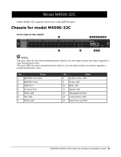
.... LED 9 Power LED 10 BMC LED 11 Speed LED 12 Management Port 13 Link/Activity LED 14 None Fan-out Port NETGEAR M4500 Series Switches Hardware Installation Guide 15 Chassis for model M4500-32C Front view of the switch NOTE: The port LEDs for the odd-numbered ports (that is , for the lower ports...
.... LED 9 Power LED 10 BMC LED 11 Speed LED 12 Management Port 13 Link/Activity LED 14 None Fan-out Port NETGEAR M4500 Series Switches Hardware Installation Guide 15 Chassis for model M4500-32C Front view of the switch NOTE: The port LEDs for the odd-numbered ports (that is , for the lower ports...
Hardware Installation Guide
Page 16
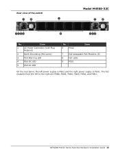
Rear view of the switch Model M4500-32C No. NETGEAR M4500 Series Switches Hardware Installation Guide 16 Item 1 AC Power Connector (with Plug Retainer) 2 Earth Grounding (M4 screw) 3 PSU Warning LED 4 PSU DC LED 5 PSU AC LED No. 6 PSU2 Item 7 Hot-swappable Fan Modules (6) 8 Fan LEDs 9 PSU1 On the rear panel, the left to the right are FAN6, FAN5, FAN4, FAN3, FAN2, and FAN1. The fan modules from the left power supply is PSU2 and the right power supply is PSU1.
Rear view of the switch Model M4500-32C No. NETGEAR M4500 Series Switches Hardware Installation Guide 16 Item 1 AC Power Connector (with Plug Retainer) 2 Earth Grounding (M4 screw) 3 PSU Warning LED 4 PSU DC LED 5 PSU AC LED No. 6 PSU2 Item 7 Hot-swappable Fan Modules (6) 8 Fan LEDs 9 PSU1 On the rear panel, the left to the right are FAN6, FAN5, FAN4, FAN3, FAN2, and FAN1. The fan modules from the left power supply is PSU2 and the right power supply is PSU1.
Hardware Installation Guide
Page 17
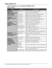
Model M4500-32C LED indicators of model M4500-32C System LEDs LED State Description PSU1 LED LED number PSU2 LED (Power Supply Unit Off LEDs, bicolor: Red (Solid) green and red) Green (Solid) One ... Green (Solid) The switch has loaded the agent software code and is operating normally Green (Blinking) The switch is loading the agent software code 17 NETGEAR M4500 Series Switches Hardware Installation Guide
Model M4500-32C LED indicators of model M4500-32C System LEDs LED State Description PSU1 LED LED number PSU2 LED (Power Supply Unit Off LEDs, bicolor: Red (Solid) green and red) Green (Solid) One ... Green (Solid) The switch has loaded the agent software code and is operating normally Green (Blinking) The switch is loading the agent software code 17 NETGEAR M4500 Series Switches Hardware Installation Guide
Hardware Installation Guide
Page 18
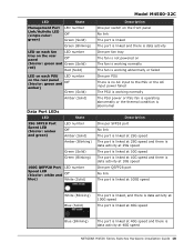
... number Off Amber (Solid) Amber (Blinking) Green (Solid) Green (Blinking) 100G QSFP28 Port LED number Speed LED (bicolor: white and Off blue) White (Solid) Model M4500-32C Description One per switch on the front panel No link The port is linked The port is linked and there is data activity One per... speed The port is linked at 40G speed Blue (Blinking) The port is linked at 40G speed and there is data activity at 40G speed NETGEAR M4500 Series Switches Hardware Installation Guide 18
... number Off Amber (Solid) Amber (Blinking) Green (Solid) Green (Blinking) 100G QSFP28 Port LED number Speed LED (bicolor: white and Off blue) White (Solid) Model M4500-32C Description One per switch on the front panel No link The port is linked The port is linked and there is data activity One per... speed The port is linked at 40G speed Blue (Blinking) The port is linked at 40G speed and there is data activity at 40G speed NETGEAR M4500 Series Switches Hardware Installation Guide 18
Hardware Installation Guide
Page 19
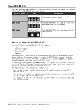
...; 1 Management port 1 Console port 1 USB port The chassis has 32 QSFP28 ports. Model M4500-32C There are 4 LEDs for each 100G QSFP28 port to install a switch runtime image or configuration file into storage memory. 19 NETGEAR M4500 Series Switches Hardware Installation Guide The chassis also provides the following system ports: One...
...; 1 Management port 1 Console port 1 USB port The chassis has 32 QSFP28 ports. Model M4500-32C There are 4 LEDs for each 100G QSFP28 port to install a switch runtime image or configuration file into storage memory. 19 NETGEAR M4500 Series Switches Hardware Installation Guide The chassis also provides the following system ports: One...
Hardware Installation Guide
Page 20
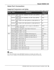
NETGEAR M4500 Series Switches Hardware Installation Guide 20 Speed Model Description Supported Distance 100G ACM761 QSFP-100G-SR4 100GBASE-SR4 MMF 100m QSFP28 Transceiver 100m ACM762 QSFP-... Optical DAC 15m 15m AXC7620 SFP+ Active Optical DAC 20m 20m NOTE: For more information about NETGEAR transceiver modules and cables, visit https://www.netgear.com/business/products/switches/modules-accessories/. Data Port Connection Model M4500-32C Supported Transceivers and Cables See the following table for the list of supported transceivers and direct-attach...
NETGEAR M4500 Series Switches Hardware Installation Guide 20 Speed Model Description Supported Distance 100G ACM761 QSFP-100G-SR4 100GBASE-SR4 MMF 100m QSFP28 Transceiver 100m ACM762 QSFP-... Optical DAC 15m 15m AXC7620 SFP+ Active Optical DAC 20m 20m NOTE: For more information about NETGEAR transceiver modules and cables, visit https://www.netgear.com/business/products/switches/modules-accessories/. Data Port Connection Model M4500-32C Supported Transceivers and Cables See the following table for the list of supported transceivers and direct-attach...
Hardware Installation Guide
Page 21
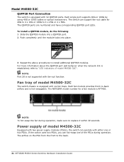
... 32 QSFP28 ports. Power supply of the PSUs during operation, make sure to "LED indicators of model M4500-32C The switch chassis is equipped with either one of model M4500-32C Equipped with two power supply modules (PSUs), the switch can support fan-out cable for a fan module...fan during operation. Model M4500-32C QSFP28 Port Connection The switch is equipped with fan-out function. Each single port supports 40G or 100G by using 40G or 100G cables or optical transceivers. Each fan module provides front-to the back. 21 NETGEAR M4500 Series Switches Hardware Installation ...
... 32 QSFP28 ports. Power supply of the PSUs during operation, make sure to "LED indicators of model M4500-32C The switch chassis is equipped with either one of model M4500-32C Equipped with two power supply modules (PSUs), the switch can support fan-out cable for a fan module...fan during operation. Model M4500-32C QSFP28 Port Connection The switch is equipped with fan-out function. Each single port supports 40G or 100G by using 40G or 100G cables or optical transceivers. Each fan module provides front-to the back. 21 NETGEAR M4500 Series Switches Hardware Installation ...
Hardware Installation Guide
Page 22
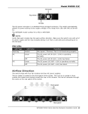
Model M4500-32C The AC power connector is operating normally. The switch automatically adjusts its power supply and fan tray modules taking in air from a cold aisle and ... / 110V) has failed. The air intake is located on the rear panel of its power setting to the hot aisle. The NETGEAR model number for a PSU is operating normally. NETGEAR M4500 Series Switches Hardware Installation Guide 22 NOTE: Verify that each module has the same airflow direction. PSU LEDs LED Type Warning AC...
Model M4500-32C The AC power connector is operating normally. The switch automatically adjusts its power supply and fan tray modules taking in air from a cold aisle and ... / 110V) has failed. The air intake is located on the rear panel of its power setting to the hot aisle. The NETGEAR model number for a PSU is operating normally. NETGEAR M4500 Series Switches Hardware Installation Guide 22 NOTE: Verify that each module has the same airflow direction. PSU LEDs LED Type Warning AC...
Hardware Installation Guide
Page 29
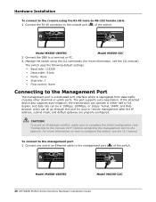
...1Gbps. CAUTION To avoid an IP address conflict, make sure to complete the initial configuration (see the CLI manual. Model M4500-48XF8C Model M4500-32C 29 NETGEAR M4500 Series Switches Hardware Installation Guide The port supports auto-negotiation. The switch uses the following default settings: Baud rate... interface which is segregated from data traffic crossing other downlink or uplink ports. For more information, see the CLI manual). Model M4500-48XF8C Model M4500-32C 2 Connect the DB9 to a terminal or PC. 3 Manage the switch using the RJ-45 male-to-RS-232 female ...
...1Gbps. CAUTION To avoid an IP address conflict, make sure to complete the initial configuration (see the CLI manual. Model M4500-48XF8C Model M4500-32C 29 NETGEAR M4500 Series Switches Hardware Installation Guide The port supports auto-negotiation. The switch uses the following default settings: Baud rate... interface which is segregated from data traffic crossing other downlink or uplink ports. For more information, see the CLI manual). Model M4500-48XF8C Model M4500-32C 2 Connect the DB9 to a terminal or PC. 3 Manage the switch using the RJ-45 male-to-RS-232 female ...

CLI Manual
Page 1
Plumeria Drive San Jose, CA 95134, USA M4500 Intelligent Fully Managed Switches Software Version 7.0.0 Model M4500-32C Model M4500-48XF8C August 2020 202-12041-03 NETGEAR, Inc. 350 E.
Plumeria Drive San Jose, CA 95134, USA M4500 Intelligent Fully Managed Switches Software Version 7.0.0 Model M4500-32C Model M4500-48XF8C August 2020 202-12041-03 NETGEAR, Inc. 350 E.
CLI Manual
Page 86
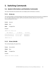
...Format show calendar Default None Mode Privileged Exec Example: (M4500-32C) #show arp This command displays connectivity between the switch and other devices from service port or management port. 5. show calendar NETGEAR M4500 Series Switches CLI Command Reference Manual 86 Format show arp... Default None Mode Privileged Exec Example: (M4500-32C) #show calendar This command displays the system time. Switching Commands 5.1. ...
...Format show calendar Default None Mode Privileged Exec Example: (M4500-32C) #show arp This command displays connectivity between the switch and other devices from service port or management port. 5. show calendar NETGEAR M4500 Series Switches CLI Command Reference Manual 86 Format show arp... Default None Mode Privileged Exec Example: (M4500-32C) #show calendar This command displays the system time. Switching Commands 5.1. ...
CLI Manual
Page 87
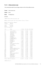
5.1.3. Format show process cpu Default None Mode Privileged Exec Example: (M4500-32C) #show process cpu This command provides the percentage utilization of Unit:1 Memory Utilization Report status KBytes free 1277836 alloc 792756 CPU Utilization: PID ... 888 RMONTask 0.00% 0.21% 0.28% 900 mlagTxTask 0.10% 0.01% 0.00% 924 openrTask 1.66% 1.86% 1.93% Total CPU Utilization 10.16% 11.30% 11.53% (M4500-32C) # NETGEAR M4500 Series Switches CLI Command Reference Manual 87 show process cpu Memory and Process CPU Utilization Info of the CPU by different tasks.
5.1.3. Format show process cpu Default None Mode Privileged Exec Example: (M4500-32C) #show process cpu This command provides the percentage utilization of Unit:1 Memory Utilization Report status KBytes free 1277836 alloc 792756 CPU Utilization: PID ... 888 RMONTask 0.00% 0.21% 0.28% 900 mlagTxTask 0.10% 0.01% 0.00% 924 openrTask 1.66% 1.86% 1.93% Total CPU Utilization 10.16% 11.30% 11.53% (M4500-32C) # NETGEAR M4500 Series Switches CLI Command Reference Manual 87 show process cpu Memory and Process CPU Utilization Info of the CPU by different tasks.
CLI Manual
Page 88
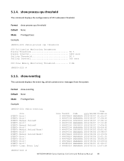
...06/01 21:29:27 0 48465024 AAAAAAAA 2016/05/31 23:07:58 (M4500-32C) # NETGEAR M4500 Series Switches CLI Command Reference Manual 88 Format show eventlog Default None Mode Privileged Exec Example: (M4500-32C) #show eventlog This command displays the event log, which contains error messages ...from the system. EVENT> Boot! EVENT> Boot! Format show process cpu threshold Default None Mode Privileged Exec Example: (M4500-32C) #show process cpu threshold This command displays the configurations of CPU utilization threshold. EVENT> Manual Reload! EVENT> Manual Reload! EVENT>...
...06/01 21:29:27 0 48465024 AAAAAAAA 2016/05/31 23:07:58 (M4500-32C) # NETGEAR M4500 Series Switches CLI Command Reference Manual 88 Format show eventlog Default None Mode Privileged Exec Example: (M4500-32C) #show eventlog This command displays the event log, which contains error messages ...from the system. EVENT> Boot! EVENT> Boot! Format show process cpu threshold Default None Mode Privileged Exec Example: (M4500-32C) #show process cpu threshold This command displays the configurations of CPU utilization threshold. EVENT> Manual Reload! EVENT> Manual Reload! EVENT>...
CLI Manual
Page 96
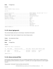
... Exec Example: (M4500-32C) #show version Switch: 1 System Description M4500-48XF8C, Runtime Code 7.0.0.1 Machine Model M4500-48XF8C Serial Number QTFCU38510002 Burned In MAC Address D8:C4:97:B5:6A:BF Software Version 7.0.0.1 Software Storage mSATA Additional Packages BGP-4 QOS Multicast IPv6 Routing Data Center OpEN API Prototype Open API (M4500-48XF8C) # 5.1.13. NETGEAR M4500 Series Switches CLI...
... Exec Example: (M4500-32C) #show version Switch: 1 System Description M4500-48XF8C, Runtime Code 7.0.0.1 Machine Model M4500-48XF8C Serial Number QTFCU38510002 Burned In MAC Address D8:C4:97:B5:6A:BF Software Version 7.0.0.1 Software Storage mSATA Additional Packages BGP-4 QOS Multicast IPv6 Routing Data Center OpEN API Prototype Open API (M4500-48XF8C) # 5.1.13. NETGEAR M4500 Series Switches CLI...


