
Hardware Installation Guide
Page 1
Campus Edge and SMB Core Chassis Switch, Blades, and Daughter Cards M6100 Hardware Installation Guide March 2020 202-12071-01 NETGEAR, Inc. 350 East Plumeria Drive San Jose, CA 95134, USA M6100 Hardware Installation M6100 -
Campus Edge and SMB Core Chassis Switch, Blades, and Daughter Cards M6100 Hardware Installation Guide March 2020 202-12071-01 NETGEAR, Inc. 350 East Plumeria Drive San Jose, CA 95134, USA M6100 Hardware Installation M6100 -
Hardware Installation Guide
Page 2
... no longer shipped with product. M6100 - Campus Edge and SMB Core Chassis Switch, Blades, and Daughter Cards Support and Community Visit netgear.com/support to "M6100 - Revision History Publication Part Number 202-12071-01 Publish Date February 2020 202-11459-01 January 2019 Comments • Name changed from "NETGEAR M6100 Chassis Switch Hardware Installation Guide" to get...
... no longer shipped with product. M6100 - Campus Edge and SMB Core Chassis Switch, Blades, and Daughter Cards Support and Community Visit netgear.com/support to "M6100 - Revision History Publication Part Number 202-12071-01 Publish Date February 2020 202-11459-01 January 2019 Comments • Name changed from "NETGEAR M6100 Chassis Switch Hardware Installation Guide" to get...

Hardware Installation Guide
Page 3
... and Daughter Cards Contents Chapter 1 About the M6100 Chassis Switch Overview of the M6100 chassis switch 6 Management ports 6 M6100 three-slot chassis switch XCM8903 6 Package contents 7 Safety instructions 8 Chapter 2 M6100 Switch Blades Blade and accessory features 12 M6100 switch blade front panels 13 15 Chapter 3 Power ...your site 23 Operating environment requirements 23 Power supply requirements 27 Chapter 5 Install a M6100 Series Chassis Unpack the XCM8903 chassis 30 Mount the M6100 chassis switch 30 Attach the sliding rails 31 Rack-mount the chassis 34 Bracket-mount the ...
... and Daughter Cards Contents Chapter 1 About the M6100 Chassis Switch Overview of the M6100 chassis switch 6 Management ports 6 M6100 three-slot chassis switch XCM8903 6 Package contents 7 Safety instructions 8 Chapter 2 M6100 Switch Blades Blade and accessory features 12 M6100 switch blade front panels 13 15 Chapter 3 Power ...your site 23 Operating environment requirements 23 Power supply requirements 27 Chapter 5 Install a M6100 Series Chassis Unpack the XCM8903 chassis 30 Mount the M6100 chassis switch 30 Attach the sliding rails 31 Rack-mount the chassis 34 Bracket-mount the ...

Hardware Installation Guide
Page 4
M6100 - Campus Edge and SMB Core Chassis Switch, Blades, and Daughter Cards Install a blank front panel 44 Remove a blank front panel 44 Chapter 7 Install or Remove Daughter Cards Install a daughter card 46 Remove a daughter card 47 Chapter 8 Replace M6100 Series Chassis Switch Components Install the fan tray 49 Remove the fan tray 49 Appendix A Technical Specifications M6100 chassis switch 52 Switch blades for M6100 chassis switch 58 Connector pinouts 58 4 M6100 Hardware Installation Guide
M6100 - Campus Edge and SMB Core Chassis Switch, Blades, and Daughter Cards Install a blank front panel 44 Remove a blank front panel 44 Chapter 7 Install or Remove Daughter Cards Install a daughter card 46 Remove a daughter card 47 Chapter 8 Replace M6100 Series Chassis Switch Components Install the fan tray 49 Remove the fan tray 49 Appendix A Technical Specifications M6100 chassis switch 52 Switch blades for M6100 chassis switch 58 Connector pinouts 58 4 M6100 Hardware Installation Guide

Hardware Installation Guide
Page 5
1 1About the M6100 Chassis Switch This chapter describes the M6100 - Campus Edge and SMB Core Chassis Switch, Blades, and Daughter Cards and includes the following sections: • Overview of the M6100 chassis switch • Management ports • M6100 three-slot chassis switch XCM8903 • Package contents For information about installing the switches, see Chapter 5, Install an M6100 Chassis Switch. 5
1 1About the M6100 Chassis Switch This chapter describes the M6100 - Campus Edge and SMB Core Chassis Switch, Blades, and Daughter Cards and includes the following sections: • Overview of the M6100 chassis switch • Management ports • M6100 three-slot chassis switch XCM8903 • Package contents For information about installing the switches, see Chapter 5, Install an M6100 Chassis Switch. 5
Hardware Installation Guide
Page 6
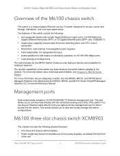
... features: • One three-slot chassis with the central processing unit (CPU) of the unit About the M6100 Chassis Switch 6 M6100 Hardware Installation Guide M6100 - The specific capabilities of the M6100 chassis switch The switch is a chassis-based, Ethernet service L3 switch designed for access, server and storage, distribution, and core layer applications. For more information about configuring...
... features: • One three-slot chassis with the central processing unit (CPU) of the unit About the M6100 Chassis Switch 6 M6100 Hardware Installation Guide M6100 - The specific capabilities of the M6100 chassis switch The switch is a chassis-based, Ethernet service L3 switch designed for access, server and storage, distribution, and core layer applications. For more information about configuring...

Hardware Installation Guide
Page 7
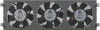
... second of an XCM8903 chassis equipped with three blades. The following items: • M6100 Chassis Switch • XCM8944 switch blade About the M6100 Chassis Switch 7 M6100 Hardware Installation Guide Campus Edge and SMB Core Chassis Switch, Blades, and Daughter Cards • Connectors at the rear of the chassis to ... chassis can support up to the fan controllers • Attachment point for optional chassis ground Package contents The M6100 Chassis Switch is packed and shipped separately. The XCM8903SK package contains the following figure shows the front of bandwidth per slot...
... second of an XCM8903 chassis equipped with three blades. The following items: • M6100 Chassis Switch • XCM8944 switch blade About the M6100 Chassis Switch 7 M6100 Hardware Installation Guide Campus Edge and SMB Core Chassis Switch, Blades, and Daughter Cards • Connectors at the rear of the chassis to ... chassis can support up to the fan controllers • Attachment point for optional chassis ground Package contents The M6100 Chassis Switch is packed and shipped separately. The XCM8903SK package contains the following figure shows the front of bandwidth per slot...
Hardware Installation Guide
Page 8
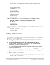
... Some devices should never be covered by NETGEAR's warranty, to the extent permissible by applicable law. • Observe and follow these guidelines can result in the appendix or the data sheet. M6100 - Campus Edge and SMB Core Chassis Switch, Blades, and Daughter Cards • ...personal safety and to your system documentation. Do not service any product except as explained in your NETGEAR product, which might not be opened. About the M6100 Chassis Switch 8 M6100 Hardware Installation Guide To reduce the risk of slide rails • Australian power cord • Japanese...
... Some devices should never be covered by NETGEAR's warranty, to the extent permissible by applicable law. • Observe and follow these guidelines can result in the appendix or the data sheet. M6100 - Campus Edge and SMB Core Chassis Switch, Blades, and Daughter Cards • ...personal safety and to your system documentation. Do not service any product except as explained in your NETGEAR product, which might not be opened. About the M6100 Chassis Switch 8 M6100 Hardware Installation Guide To reduce the risk of slide rails • Australian power cord • Japanese...

Hardware Installation Guide
Page 9
...Hz in western Japan - 230V, 50 Hz in your location. • Depending on your device uses a power cable: About the M6100 Chassis Switch 9 M6100 Hardware Installation Guide If you follow the operating instructions. • Keep your system away from the electrical outlet and replace the part or...to water. - Campus Edge and SMB Core Chassis Switch, Blades, and Daughter Cards - If your device, the power adapter, power adapter cable, power cable, extension cable, or plug is set to match the power at your local NETGEAR reseller. - M6100 - Depending on your device, use only a supplied...
...Hz in western Japan - 230V, 50 Hz in your location. • Depending on your device uses a power cable: About the M6100 Chassis Switch 9 M6100 Hardware Installation Guide If you follow the operating instructions. • Keep your system away from the electrical outlet and replace the part or...to water. - Campus Edge and SMB Core Chassis Switch, Blades, and Daughter Cards - If your device, the power adapter, power adapter cable, power cable, extension cable, or plug is set to match the power at your local NETGEAR reseller. - M6100 - Depending on your device, use only a supplied...

Hardware Installation Guide
Page 10
... a surge suppressor, line conditioner, or uninterruptible power supply (UPS). • Position system cables, power adapter cables, or power cables carefully. About the M6100 Chassis Switch 10 M6100 Hardware Installation Guide M6100 - The power cable must be rated for the product and for site modifications. • Always follow your country. - The voltage and current rating...
... a surge suppressor, line conditioner, or uninterruptible power supply (UPS). • Position system cables, power adapter cables, or power cables carefully. About the M6100 Chassis Switch 10 M6100 Hardware Installation Guide M6100 - The power cable must be rated for the product and for site modifications. • Always follow your country. - The voltage and current rating...

Hardware Installation Guide
Page 11
2 2M6100 Switch Blades This chapter includes the following sections: • Blade and accessory features • M6100 switch blade front panels 11
2 2M6100 Switch Blades This chapter includes the following sections: • Blade and accessory features • M6100 switch blade front panels 11
Hardware Installation Guide
Page 12
... SFP+ ports (shared). • XCM89P PoE+ daughter card. Campus Edge and SMB Core Chassis Switch, Blades, and Daughter Cards Blade and accessory features The NETGEAR M6100 Series Switch Blades are state-of-the-art, high-performance, IEEE-compliant network solutions. For use with XCM8944 ...and XCM8948 blades. • XCM89UP UPoE daughter card. The M6100 Chassis Switch can use with XCM8944 and XCM8948 blades...
... SFP+ ports (shared). • XCM89P PoE+ daughter card. Campus Edge and SMB Core Chassis Switch, Blades, and Daughter Cards Blade and accessory features The NETGEAR M6100 Series Switch Blades are state-of-the-art, high-performance, IEEE-compliant network solutions. For use with XCM8944 ...and XCM8948 blades. • XCM89UP UPoE daughter card. The M6100 Chassis Switch can use with XCM8944 and XCM8948 blades...

Hardware Installation Guide
Page 13
... port ports USB port 1G RJ-45 ports Note: OoB stands for Out of the following figures show the front panels of the M6100 Series Switch Blades. The SFP+ ports support any combination of Band management for local browser user interface, Telnet or SSH access.... M6100 - Campus Edge and SMB Core Chassis Switch, Blades, and Daughter Cards M6100 switch blade front panels The following modules: 10GBASE-SR SFP+ Module AXM761, 10GBASE-LR SFP+ Module AXM762, and 10GBASE-LRM SFP+ ...
... port ports USB port 1G RJ-45 ports Note: OoB stands for Out of the following figures show the front panels of the M6100 Series Switch Blades. The SFP+ ports support any combination of Band management for local browser user interface, Telnet or SSH access.... M6100 - Campus Edge and SMB Core Chassis Switch, Blades, and Daughter Cards M6100 switch blade front panels The following modules: 10GBASE-SR SFP+ Module AXM761, 10GBASE-LR SFP+ Module AXM762, and 10GBASE-LRM SFP+ ...

Hardware Installation Guide
Page 14
...circuit - Packet transmission or reception is established on the port at 1000 Mbps. • Solid yellow. PoE power demand exceeds power available. - M6100 Switch Blades 14 M6100 Hardware Installation Guide M6100 series front panels Table 1. The chassis is established on the port. • Solid green. The system is supplying power successfully. • Solid...No link is a member but without a supervisor blade. One of proper voltage band (44-57 VDC for PoE 802.3af, 50-57 VDC for M6100 Series Switches LED Blade Power Chassis Power/Status (at 10/100 Mbps.
...circuit - Packet transmission or reception is established on the port at 1000 Mbps. • Solid yellow. PoE power demand exceeds power available. - M6100 Switch Blades 14 M6100 Hardware Installation Guide M6100 series front panels Table 1. The chassis is established on the port. • Solid green. The system is supplying power successfully. • Solid...No link is a member but without a supervisor blade. One of proper voltage band (44-57 VDC for PoE 802.3af, 50-57 VDC for M6100 Series Switches LED Blade Power Chassis Power/Status (at 10/100 Mbps.

Hardware Installation Guide
Page 15
Campus Edge and SMB Core Chassis Switch, Blades, and Daughter Cards Table 1. LED descriptions for M6100 Series Switches (continued) LED 1G SFP ports (1 LED per port) 10G copper ports 10G SFP+ ports OOB Port Description SPD/Link/ACT LED: • Off..... • Blinking yellow. Left side LED - 1Gbps Link/ACT LED: • Off. No link is established on the port. • Solid green. M6100 Switch Blades 15 M6100 Hardware Installation Guide A valid 1000 Mbps SFP module link is occurring on the port. • Blinking green. Packet transmission or reception is established on...
Campus Edge and SMB Core Chassis Switch, Blades, and Daughter Cards Table 1. LED descriptions for M6100 Series Switches (continued) LED 1G SFP ports (1 LED per port) 10G copper ports 10G SFP+ ports OOB Port Description SPD/Link/ACT LED: • Off..... • Blinking yellow. Left side LED - 1Gbps Link/ACT LED: • Off. No link is established on the port. • Solid green. M6100 Switch Blades 15 M6100 Hardware Installation Guide A valid 1000 Mbps SFP module link is occurring on the port. • Blinking green. Packet transmission or reception is established on...

Hardware Installation Guide
Page 16
After the system is powered by 100-240 VAC power supply units (PSUs). 3 3Power Supply Units The M6100 Switch Chassis is properly configured, if one PSU fails, the others provide sufficient power to operate a fully loaded switch. AC power supplies in the M6100 series chassis switch are fully fault tolerant and load-sharing in an N+1 configuration. This chapter includes the following sections: • Overview of the 100-240 VAC power supply unit APS1000W • Specifications • Install the PSUs • Remove or replace a PSU • Install blank PSU panels 16
After the system is powered by 100-240 VAC power supply units (PSUs). 3 3Power Supply Units The M6100 Switch Chassis is properly configured, if one PSU fails, the others provide sufficient power to operate a fully loaded switch. AC power supplies in the M6100 series chassis switch are fully fault tolerant and load-sharing in an N+1 configuration. This chapter includes the following sections: • Overview of the 100-240 VAC power supply unit APS1000W • Specifications • Install the PSUs • Remove or replace a PSU • Install blank PSU panels 16

Hardware Installation Guide
Page 17
...through the front vents of the airflow through the PSU is in an M6100 series switch can accommodate up to 63 Hz AC input. More installed PSUs are needed... low-line power range is used to the system if the AC input is independent of the switch. The software determines the maximum available power required for repair or replacement. The power supply bay ...serviceable parts. If the PSU fails, return the defective PSU for the switch and enables the modules accordingly. Power Supply Units 17 M6100 Hardware Installation Guide Airflow through the rest of the 100-240 VAC power ...
...through the front vents of the airflow through the PSU is in an M6100 series switch can accommodate up to 63 Hz AC input. More installed PSUs are needed... low-line power range is used to the system if the AC input is independent of the switch. The software determines the maximum available power required for repair or replacement. The power supply bay ...serviceable parts. If the PSU fails, return the defective PSU for the switch and enables the modules accordingly. Power Supply Units 17 M6100 Hardware Installation Guide Airflow through the rest of the 100-240 VAC power ...

Hardware Installation Guide
Page 18
... this connection is not overloaded. Install the PSUs CAUTION: Do not force the power supply into place. 2. Power Supply Units 18 M6100 Hardware Installation Guide Remove the plug from the electrical outlet to disconnect power to prevent overcurrent conditions. Carefully slide the power supply all the... that the PSU circuit is easily accessible. To install the PSUs: 1. Campus Edge and SMB Core Chassis Switch, Blades, and Daughter Cards CAUTION: The PSU does not include a switch for turning the unit on and off. Plugging an uninstalled PSU into an electrical outlet exposes you to a...
... this connection is not overloaded. Install the PSUs CAUTION: Do not force the power supply into place. 2. Power Supply Units 18 M6100 Hardware Installation Guide Remove the plug from the electrical outlet to disconnect power to prevent overcurrent conditions. Carefully slide the power supply all the... that the PSU circuit is easily accessible. To install the PSUs: 1. Campus Edge and SMB Core Chassis Switch, Blades, and Daughter Cards CAUTION: The PSU does not include a switch for turning the unit on and off. Plugging an uninstalled PSU into an electrical outlet exposes you to a...

Hardware Installation Guide
Page 19
...input on the PSU. b. Completely disconnect and remove the old power cord. Power Supply Units 19 M6100 Hardware Installation Guide Leave the AC power cord in place or replace it: • If you ...will use thermal protective gloves when handling the PSU during removal. Campus Edge and SMB Core Chassis Switch, Blades, and Daughter Cards 4. After all the power supplies are replacing only the power supply and.... 2. Lift the handle on the front of the switch and then connect the opposite end of the AC power cord to the touch; M6100 - WARNING: Be sure that the source outlet is properly...
...input on the PSU. b. Completely disconnect and remove the old power cord. Power Supply Units 19 M6100 Hardware Installation Guide Leave the AC power cord in place or replace it: • If you ...will use thermal protective gloves when handling the PSU during removal. Campus Edge and SMB Core Chassis Switch, Blades, and Daughter Cards 4. After all the power supplies are replacing only the power supply and.... 2. Lift the handle on the front of the switch and then connect the opposite end of the AC power cord to the touch; M6100 - WARNING: Be sure that the source outlet is properly...

Hardware Installation Guide
Page 20
...Max 60W 12 per port): Off 13 = no PD 14 Green = Po1E5powere1d6Yellow 17 = PoE 18 fault RJ4159SPD/Lin2k0/Act 4. Remove the PSU from the switch. 5. Push the locking handle in Install the PSUs on page 19. For more information about removing a PSU, see Remove or replace a PSU on page ...18. Power Supply Units 20 M6100 Hardware Installation Guide Slide the PSU partway out of the power supply bay. Install blank PSU panels CAUTION: The PSU might be hot to support...
...Max 60W 12 per port): Off 13 = no PD 14 Green = Po1E5powere1d6Yellow 17 = PoE 18 fault RJ4159SPD/Lin2k0/Act 4. Remove the PSU from the switch. 5. Push the locking handle in Install the PSUs on page 19. For more information about removing a PSU, see Remove or replace a PSU on page ...18. Power Supply Units 20 M6100 Hardware Installation Guide Slide the PSU partway out of the power supply bay. Install blank PSU panels CAUTION: The PSU might be hot to support...


