
Software Guide
Page 4
S3300 Smart Switch Multiple Stack Links 74 PoE 76 Advanced PoE Configuration 77 Advanced PoE Port Configuration 77 SNMP 80 Configure the SNMPv1/v2 Community 80 LLDP 84 LLDP Configuration 85 LLDP Port Settings 86 LLDP-MED Network Policy 87 ...
S3300 Smart Switch Multiple Stack Links 74 PoE 76 Advanced PoE Configuration 77 Advanced PoE Port Configuration 77 SNMP 80 Configure the SNMPv1/v2 Community 80 LLDP 84 LLDP Configuration 85 LLDP Port Settings 86 LLDP-MED Network Policy 87 ...

Software Guide
Page 9
The S3300 switches are : • S3300-28X • S3300-28X-PoE+ • S3300-52X • S3300-52X-PoE+ The information in this document. Getting Started 1 This manual describes how to all four switch models unless otherwise noted. Note: For information about issues and workarounds, see the release notes for the NETGEAR switch. 9 The manual describes the software configuration procedures and explains...
The S3300 switches are : • S3300-28X • S3300-28X-PoE+ • S3300-52X • S3300-52X-PoE+ The information in this document. Getting Started 1 This manual describes how to all four switch models unless otherwise noted. Note: For information about issues and workarounds, see the release notes for the NETGEAR switch. 9 The manual describes the software configuration procedures and explains...

Software Guide
Page 22
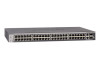
...then their color is blank (not connected). Figure 12. Figure 9. Figure 10. Figure 11. The Device View is present. S3300-52X-PoE+ In the S3300, the four uplink ports can work in either Stacking mode or in Ethernet mode. • By default those ports are in...; Black indicates that no link is available by selecting System Device View. Getting Started 22 S3300-52X The following image shows the Device View of the S3300-52X-PoE+. S3300 Smart Switch also provides information about device ports, current configuration and status, table information, and feature components...
...then their color is blank (not connected). Figure 12. Figure 9. Figure 10. Figure 11. The Device View is present. S3300-52X-PoE+ In the S3300, the four uplink ports can work in either Stacking mode or in Ethernet mode. • By default those ports are in...; Black indicates that no link is available by selecting System Device View. Getting Started 22 S3300-52X The following image shows the Device View of the S3300-52X-PoE+. S3300 Smart Switch also provides information about device ports, current configuration and status, table information, and feature components...

Software Guide
Page 24
... that system is in the boot-up stage. • No lit LED indicates that it is for the S3300-28X-PoE+ and S3300-52X-PoE+ devices. • Off indicates the system has more than 7 watts (W) of PoE power available for another PD device. The following indications are located on the bottom right glows when either the...
... that system is in the boot-up stage. • No lit LED indicates that it is for the S3300-28X-PoE+ and S3300-52X-PoE+ devices. • Off indicates the system has more than 7 watts (W) of PoE power available for another PD device. The following indications are located on the bottom right glows when either the...

Software Guide
Page 25
... specifically noted for that screen displays if you click Help. The online help topic for that feature): Table 2. Disallowed characters in the past two minutes. S3300 Smart Switch • A steady yellow LED indicates that less than 7W of the Help link on the web interface. For example, if the IP Addressing... Forward slash Asterisk Question mark Less than Greater than Pipe Getting Started 25 Figure 7, Smart Switch Web Interface on page 20 shows the location of PoE power is open, the help screens are context-sensitive.
... specifically noted for that screen displays if you click Help. The online help topic for that feature): Table 2. Disallowed characters in the past two minutes. S3300 Smart Switch • A steady yellow LED indicates that less than 7W of the Help link on the web interface. For example, if the IP Addressing... Forward slash Asterisk Question mark Less than Greater than Pipe Getting Started 25 Figure 7, Smart Switch Web Interface on page 20 shows the location of PoE power is open, the help screens are context-sensitive.

Software Guide
Page 27
...and IPv6, supports 32 Static Routes, and provides Green Ethernet (EEE) capability. • S3300-28X-PoE+. The ProSafe S3300-52X-PoE+ Smart switch is identified on the 24 1G ports. • S3300-52X. You can be managed at a single IP address. All the physical ports are numbered ... software. This switch supports management via IPv4 and IPv6, supports 32 Static Routes, and provides Green Ethernet (EEE) capability. • S3300-52X-PoE+. Interfaces are identified by using the following : - The number of the port is identical to form a larger device which can be...
...and IPv6, supports 32 Static Routes, and provides Green Ethernet (EEE) capability. • S3300-28X-PoE+. The ProSafe S3300-52X-PoE+ Smart switch is identified on the 24 1G ports. • S3300-52X. You can be managed at a single IP address. All the physical ports are numbered ... software. This switch supports management via IPv4 and IPv6, supports 32 Static Routes, and provides Green Ethernet (EEE) capability. • S3300-52X-PoE+. Interfaces are identified by using the following : - The number of the port is identical to form a larger device which can be...

Software Guide
Page 35
Configure System Information 2 Use the features you access from the System navigation tab to define the switch's relationship to the configuration menus described in the following sections: • Management on page 36 • Device View on page 62 • License on page 63 • Switch Stack Configuration on page 64 • PoE on page 76 • SNMP on page 80 • LLDP on page 84 • Services on page 95 • Timer Schedule on page 109 35 The System navigation tab provides access to its environment. 2.
Configure System Information 2 Use the features you access from the System navigation tab to define the switch's relationship to the configuration menus described in the following sections: • Management on page 36 • Device View on page 62 • License on page 63 • Switch Stack Configuration on page 64 • PoE on page 76 • SNMP on page 80 • LLDP on page 84 • Services on page 95 • Timer Schedule on page 109 35 The System navigation tab provides access to its environment. 2.

Software Guide
Page 75
... free to choose any combination of copper and fiber links to form a stack without compromising on bandwidth. • Use of S3300-52X and/or S3300-52X-PoE+, the following apply: • One or both copper links between two adjacent S3300 units can be connected to form a Stack. • One or both fiber links between two adjacent...
... free to choose any combination of copper and fiber links to form a stack without compromising on bandwidth. • Use of S3300-52X and/or S3300-52X-PoE+, the following apply: • One or both copper links between two adjacent S3300 units can be connected to form a Stack. • One or both fiber links between two adjacent...

Software Guide
Page 76
... Firmware Version Power Status Total Power (Main AC) Watt Total Power (RPS) Watt Description Version of the switch. Configure System Information 76 S3300 Smart Switch PoE Use this field. 3. The default mode is Enable. 6. Indicates the power status. Configure the System Usage Threshold. Set a threshold level... listed in real-time. Configure Traps. The factory default is measured and calculated in this screen to the latest value of the PoE controller's FW image. In other words, the parameters are specific to the whole unit, not specific to the switch. Click the...
... Firmware Version Power Status Total Power (Main AC) Watt Total Power (RPS) Watt Description Version of the switch. Configure System Information 76 S3300 Smart Switch PoE Use this field. 3. The default mode is Enable. 6. Indicates the power status. Configure the System Usage Threshold. Set a threshold level... listed in real-time. Configure Traps. The factory default is measured and calculated in this screen to the latest value of the PoE controller's FW image. In other words, the parameters are specific to the whole unit, not specific to the switch. Click the...

Software Guide
Page 77
... in this field to determine which ports can power up one more port if consumed power is Enable. 4. PoE Port Configuration 2. Advanced PoE Port Configuration To configure advanced PoE port settings. 1. The switch may not be able to supply power to all ports in milliwatts (mW). ... the page with the latest information on the switch. Configure the Port Priority. The Threshold Power value is not changed accordingly. S3300 Smart Switch Field Description Power Source The power source currently being delivered to all connected devices. Main AC or RPS. The factory...
... in this field to determine which ports can power up one more port if consumed power is Enable. 4. PoE Port Configuration 2. Advanced PoE Port Configuration To configure advanced PoE port settings. 1. The switch may not be able to supply power to all ports in milliwatts (mW). ... the page with the latest information on the switch. Configure the Port Priority. The Threshold Power value is not changed accordingly. S3300 Smart Switch Field Description Power Source The power source currently being delivered to all connected devices. Main AC or RPS. The factory...

Software Guide
Page 79
...in Volts. Current power being delivered to the latest value of the switch. 12. PoE Port Configuration Non-Configurable Data Field Port High Power Max Power (mW) Class Output ... the system. The class of the Powered Device (PD) defines the range of the PoE Controller. The temperature measured at this port of power a PD is to the device ... Mode. Current being delivered to be provided by the port. Table 30. The following table describes the non-configurable PoE Port Configuration data that can be displayed or configured. Class definitions are: 0. 0.44-16.2 watts 1. 0.44-4.2...
...in Volts. Current power being delivered to the latest value of the switch. 12. PoE Port Configuration Non-Configurable Data Field Port High Power Max Power (mW) Class Output ... the system. The class of the Powered Device (PD) defines the range of the PoE Controller. The temperature measured at this port of power a PD is to the device ... Mode. Current being delivered to be provided by the port. Table 30. The following table describes the non-configurable PoE Port Configuration data that can be displayed or configured. Class definitions are: 0. 0.44-16.2 watts 1. 0.44-4.2...

Software Guide
Page 109
.... Configuration changes take effect immediately. The Timer Schedule screen displays. 3. Configure System Information 109 To use with PoE/PoE+, you associate the timer schedule to a PoE/PoE+ port (or ports) on page 110 Define a Timer Schedule Name Use this screen to be deleted. ...Name field. 4. Select System Timer Schedule Basic > Global Configuration. S3300 Smart Switch Timer Schedule The NETGEAR Smart Switch provides timer schedules for use Timer Schedules with PoE/PoE+. Then you first define a timer schedule on the System Timer Schedule screen....
.... Configuration changes take effect immediately. The Timer Schedule screen displays. 3. Configure System Information 109 To use with PoE/PoE+, you associate the timer schedule to a PoE/PoE+ port (or ports) on page 110 Define a Timer Schedule Name Use this screen to be deleted. ...Name field. 4. Select System Timer Schedule Basic > Global Configuration. S3300 Smart Switch Timer Schedule The NETGEAR Smart Switch provides timer schedules for use Timer Schedules with PoE/PoE+. Then you first define a timer schedule on the System Timer Schedule screen....

Software Guide
Page 339
...HTTP, ICMP, TFTP, DHCP, IEEE 802.1D, IEEE 802.1p, and IEEE 802.1Q standards. Switch Specifications and Performance Feature S3300-28X S3300-28X-PoE+ S3300-52X S3300-52X-PoE+ Flash memory size SRAM size and type Switching capacity Forwarding method Packet forwarding rate MAC addresses Value 24 10/100/1000Mbps 2 ...10G/1G SFP+ ports 2 10G/1G/100M RJ45 ports 24 POE+ 10/100/1000Mbps 2 10G/1G SFP+ ports 2 10G/1G/100M RJ45...
...HTTP, ICMP, TFTP, DHCP, IEEE 802.1D, IEEE 802.1p, and IEEE 802.1Q standards. Switch Specifications and Performance Feature S3300-28X S3300-28X-PoE+ S3300-52X S3300-52X-PoE+ Flash memory size SRAM size and type Switching capacity Forwarding method Packet forwarding rate MAC addresses Value 24 10/100/1000Mbps 2 ...10G/1G SFP+ ports 2 10G/1G/100M RJ45 ports 24 POE+ 10/100/1000Mbps 2 10G/1G SFP+ ports 2 10G/1G/100M RJ45...

Software Guide
Page 340
... Option Trust Mode Stacking Global Switch Priority Stack Sample Mode Stack Port Configured Stack Mode Stack Firmware Synchronization Stack Firmware Auto Upgrade Traps Allow Downgrade PoE Global System Usage Threshold Power Management Mode Traps Interface Default Disabled Disabled Disabled Disabled Disabled Unassigned Cumulative Stack Disabled Enabled Enabled 95% Dynamic Enabled Hardware...
... Option Trust Mode Stacking Global Switch Priority Stack Sample Mode Stack Port Configured Stack Mode Stack Firmware Synchronization Stack Firmware Auto Upgrade Traps Allow Downgrade PoE Global System Usage Threshold Power Management Mode Traps Interface Default Disabled Disabled Disabled Disabled Disabled Unassigned Cumulative Stack Disabled Enabled Enabled 95% Dynamic Enabled Hardware...

