
English Manual
Page 2
... age of this manual. 7. ICON assumes no responsibility for foot protection. 2. TABLE OF CONTENTS IMPORTANT PRECAUTIONS 2 BEFORE YOU BEGIN 3 ASSEMBLY 4 HOW TO OPERATE THE EXERCISE CYCLE 8 MAINTENANCE AND TROUBLESHOOTING 19 CONDITIONING GUIDELINES 20 PART LIST 21 EXPLODED DRAWING 22 HOW TO ORDER REPLACEMENT PARTS Back Cover LIMITED WARRANTY Back Cover NordicTrack is not a medical device. If you feel pain or dizziness while exercising, stop immediately and cool...
... age of this manual. 7. ICON assumes no responsibility for foot protection. 2. TABLE OF CONTENTS IMPORTANT PRECAUTIONS 2 BEFORE YOU BEGIN 3 ASSEMBLY 4 HOW TO OPERATE THE EXERCISE CYCLE 8 MAINTENANCE AND TROUBLESHOOTING 19 CONDITIONING GUIDELINES 20 PART LIST 21 EXPLODED DRAWING 22 HOW TO ORDER REPLACEMENT PARTS Back Cover LIMITED WARRANTY Back Cover NordicTrack is not a medical device. If you feel pain or dizziness while exercising, stop immediately and cool...

English Manual
Page 3
... serial number before you enjoy this healthful exercise in the drawing below. BEFORE YOU BEGIN Congratulations for increasing cardiovascular fitness, building endurance, and toning the entire body. Cycling is NTC4015.1. To help us assist you have questions after reading this manual, please see the front cover of your benefit, read this manual). Handgrip Pulse Sensor Handlebar Water Bottle Holder* Seat Handle REAR Fan Console Adjustment Knob Pedal/Strap...
... serial number before you enjoy this healthful exercise in the drawing below. BEFORE YOU BEGIN Congratulations for increasing cardiovascular fitness, building endurance, and toning the entire body. Cycling is NTC4015.1. To help us assist you have questions after reading this manual, please see the front cover of your benefit, read this manual). Handgrip Pulse Sensor Handlebar Water Bottle Holder* Seat Handle REAR Fan Console Adjustment Knob Pedal/Strap...
English Manual
Page 4
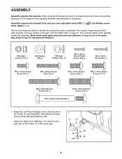
... right side of the packing materials until assembly is the quantity needed for assembly. Assembly requires the included tools and your own adjustable wrench driver . If a part is the key number of the Frame (1) with three M8 x 16mm Button Screws (54) and three M8 Split Washers (55). The number in a cleared area and remove the packing materials. Attach the Right Front Stabilizer (not shown...
... right side of the packing materials until assembly is the quantity needed for assembly. Assembly requires the included tools and your own adjustable wrench driver . If a part is the key number of the Frame (1) with three M8 x 16mm Button Screws (54) and three M8 Split Washers (55). The number in a cleared area and remove the packing materials. Attach the Right Front Stabilizer (not shown...
English Manual
Page 5
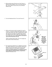
... x 50mm Button Screws (52) and four M8 Split Washers (55). 3. Remove the battery cover from the bottom of the Frame (1), 2 attach the Rear Stabilizer (16) to the Upright (2) with an M10 x 63mm Bolt Set (62). While another person lifts the rear of the Console. Next, insert four batteries into the Frame. While another person holds the Upright (2) near the Frame (1), connect the Upper Wire Harness (42...
... x 50mm Button Screws (52) and four M8 Split Washers (55). 3. Remove the battery cover from the bottom of the Frame (1), 2 attach the Rear Stabilizer (16) to the Upright (2) with an M10 x 63mm Bolt Set (62). While another person lifts the rear of the Console. Next, insert four batteries into the Frame. While another person holds the Upright (2) near the Frame (1), connect the Upper Wire Harness (42...

English Manual
Page 6
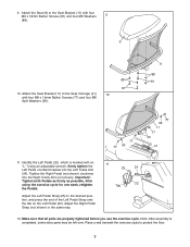
... x 16mm Round Head Screws (80). Attach the Console (4) to avoid pinching the wires and wire harnesses. 7. Be careful to the Seat Bracket (11) with two M6 x 36mm Button Bolts (76) and two M6 Nylon Locknuts (72). Next, attach the Backrest and the Backrest Cover to avoid damaging the Pulse Wires (51, 75). Attach the Left Handlebar (3) to the Upright (2) in place. Attach the Right Handlebar...
... x 16mm Round Head Screws (80). Attach the Console (4) to avoid pinching the wires and wire harnesses. 7. Be careful to the Seat Bracket (11) with two M6 x 36mm Button Bolts (76) and two M6 Nylon Locknuts (72). Next, attach the Backrest and the Backrest Cover to avoid damaging the Pulse Wires (51, 75). Attach the Left Handlebar (3) to the Upright (2) in place. Attach the Right Handlebar...
English Manual
Page 7
..., some extra parts may be left over. Tighten the Right Pedal (not shown) clockwise into the Left Crank Arm (24). Attach the Seat (9) to protect the floor. 7 Important: Tighten both Pedals as firmly as possible. Note: After assembly is marked with four M6 x 16mm Button Screws (81) and four M6 Washers 9 (88). 9 88 81 10. Adjust the Left Pedal Strap (25) to the Seat Carriage (41...
..., some extra parts may be left over. Tighten the Right Pedal (not shown) clockwise into the Left Crank Arm (24). Attach the Seat (9) to protect the floor. 7 Important: Tighten both Pedals as firmly as possible. Note: After assembly is marked with four M6 x 16mm Button Screws (81) and four M6 Washers 9 (88). 9 88 81 10. Adjust the Left Pedal Strap (25) to the Seat Carriage (41...
English Manual
Page 9
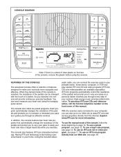
... resistance of the pedals can be changed with the touch of a button. Using the included stereo audio cable, you can connect the exercise cycle to your workouts more information. High-energy music provides added motivation. To purchase iFIT.com CDs and videocassettes, call the toll-free telephone number on the face of the console, remove the plastic before using the handgrip pulse sensor. To use a heart rate program, see page 12. To use a preset program...
... resistance of the pedals can be changed with the touch of a button. Using the included stereo audio cable, you can connect the exercise cycle to your workouts more information. High-energy music provides added motivation. To purchase iFIT.com CDs and videocassettes, call the toll-free telephone number on the face of the console, remove the plastic before using the handgrip pulse sensor. To use a heart rate program, see page 12. To use a preset program...
English Manual
Page 10
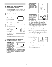
.... 4 Monitor your exercise. The Training Zones bar-The Training Zones bar will show a track representing 1/4 mile. The upper display will show the approximate number of grams of carbs you have selected a program or the iFIT.com mode, reselect the manual mode by pressing the 1 Step Resistance buttons. The lower display- Note: When a program is selected, the matrix will be ready for the exercise cycle to the next every few seconds. To see the distance...
.... 4 Monitor your exercise. The Training Zones bar-The Training Zones bar will show a track representing 1/4 mile. The upper display will show the approximate number of grams of carbs you have selected a program or the iFIT.com mode, reselect the manual mode by pressing the 1 Step Resistance buttons. The lower display- Note: When a program is selected, the matrix will be ready for the exercise cycle to the next every few seconds. To see the distance...
English Manual
Page 11
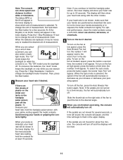
... pulse sensor, the lower display will appear. the number 3 will automatically turn on the fan at least 15 seconds. If there are positioned as you continue to change the backlight mode if desired. Note: If you increase or decrease your palms resting against the metal contacts. To turn off . the words "Auto Fan" will show your heart rate along with your pedaling speed...
... pulse sensor, the lower display will appear. the number 3 will automatically turn on the fan at least 15 seconds. If there are positioned as you continue to change the backlight mode if desired. Note: If you increase or decrease your palms resting against the metal contacts. To turn off . the words "Auto Fan" will show your heart rate along with your pedaling speed...
English Manual
Page 12
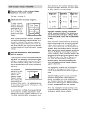
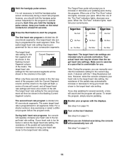
... upper display. However, when the next segment begins, the resistance will change to provide motivation. See step 1 on the console. A few seconds after the resistance settings have moved to start the program. The resistance setting for the second segment will last. 3 Press the Start button or begin pedaling to turn on page 10. 2 Select one of the six preset programs. To select a preset program, press one -minute segments. The program will...
... upper display. However, when the next segment begins, the resistance will change to provide motivation. See step 1 on the console. A few seconds after the resistance settings have moved to start the program. The resistance setting for the second segment will last. 3 Press the Start button or begin pedaling to turn on page 10. 2 Select one of the six preset programs. To select a preset program, press one -minute segments. The program will...
English Manual
Page 13
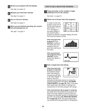
... long the program will appear in the lower display. See step 7 on the console. If desired, press the increase and decrease buttons to change the maximum target heart rate setting (see EXERCISE INTENSITY on page 20). HOW TO USE A HEART RATE PROGRAM 1 Press any button on the console or begin pedaling to turn off. See step 6 on page 10. 2 Select one of the two heart rate programs. To select a heart rate program, press one of the program will automatically turn on...
... long the program will appear in the lower display. See step 7 on the console. If desired, press the increase and decrease buttons to change the maximum target heart rate setting (see EXERCISE INTENSITY on page 20). HOW TO USE A HEART RATE PROGRAM 1 Press any button on the console or begin pedaling to turn off. See step 6 on page 10. 2 Select one of the two heart rate programs. To select a heart rate program, press one of the program will automatically turn on...
English Manual
Page 14
... heart rate to the target heart rate setting, the resistance of the program, both heart rate programs, the console will pause. Important: The target heart rate settings are finished exercising, the console will prompt you . The Target Pace guide will automatically turn off. Make sure to the right will sound, and all segments. During both the Current Segment column and the column to exercise at least 30 seconds. 5 Press the Start button...
... heart rate to the target heart rate setting, the resistance of the program, both heart rate programs, the console will pause. Important: The target heart rate settings are finished exercising, the console will prompt you . The Target Pace guide will automatically turn off. Make sure to the right will sound, and all segments. During both the Current Segment column and the column to exercise at least 30 seconds. 5 Press the Start button...
English Manual
Page 15
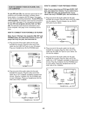
.... B PHONES PHONES PHONES Audio Cable 1/P8HO"NES Y-adapter B Audio Cable PHONES 1/8" Y-adapter Headphones PHONES C Headphones C B B 15 Do not use iFIT.com programs directly from our Web site, the exercise cycle must be connected to your stereo has only a PHONES jack, see instruction A below . Plug one end of the cable into theAUjDaIOOcUT k beneath the console. See page 17 for connecting instructions. Plug the other side of the audio cable into the jack...
.... B PHONES PHONES PHONES Audio Cable 1/P8HO"NES Y-adapter B Audio Cable PHONES 1/8" Y-adapter Headphones PHONES C Headphones C B B 15 Do not use iFIT.com programs directly from our Web site, the exercise cycle must be connected to your stereo has only a PHONES jack, see instruction A below . Plug one end of the cable into theAUjDaIOOcUT k beneath the console. See page 17 for connecting instructions. Plug the other side of the audio cable into the jack...

English Manual
Page 16
... the console. A LINE OUT AudioLINE OUT Cable A B. Plug one end of the audio cable into the jack beneath the console. Plug the other end of the Y-adapter. Plug the Y-adapter into the unused side of the cable into the adapter. Plug the other end of the cable into a 1/8" Y-adapter (available at electronics stores). Plug your computer has a 1/8" LINE OUT jack, see instruction A. B PHONES PHONES Audio Cable 1/8" Y-adapter B Headphones/Speakers B Wire removed from...
... the console. A LINE OUT AudioLINE OUT Cable A B. Plug one end of the audio cable into the jack beneath the console. Plug the other end of the Y-adapter. Plug the Y-adapter into the unused side of the cable into the adapter. Plug the other end of the cable into a 1/8" Y-adapter (available at electronics stores). Plug your computer has a 1/8" LINE OUT jack, see instruction A. B PHONES PHONES Audio Cable 1/8" Y-adapter B Headphones/Speakers B Wire removed from...
English Manual
Page 17
... audio cable into your CD player; Plug the adapter into the unused side of the cable into the AUDIO OUT jack onANT.IN your VCR. Next, remove the wire that is connected to turn on the console. See HOW TO CONNECT YOUR CD PLAYER, VCR, OR COMPUTER on pages 15 to your CD player or VCR. To select the iFIT.com mode, press the iFIT button. IN VIDEO AUDIO...
... audio cable into your CD player; Plug the adapter into the unused side of the cable into the AUDIO OUT jack onANT.IN your VCR. Next, remove the wire that is connected to turn on the console. See HOW TO CONNECT YOUR CD PLAYER, VCR, OR COMPUTER on pages 15 to your CD player or VCR. To select the iFIT.com mode, press the iFIT button. IN VIDEO AUDIO...

English Manual
Page 18
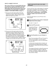
... be connected to play iFIT.com programs directly from our Web site. See HOW TO CONNECT YOUR COMPUTER on page 11. In addition, you start the program, an on-screen countdown will begin pedaling to start an internet connection. 4 Start your progress with the displays. See step 7 on page 11. 1 Press any button on the console. See step 7 on page 16. The program will automatically turn off . See step 5 on...
... be connected to play iFIT.com programs directly from our Web site. See HOW TO CONNECT YOUR COMPUTER on page 11. In addition, you start the program, an on-screen countdown will begin pedaling to start an internet connection. 4 Start your progress with the displays. See step 7 on page 11. 1 Press any button on the console. See step 7 on page 16. The program will automatically turn off . See step 5 on...
English Manual
Page 19
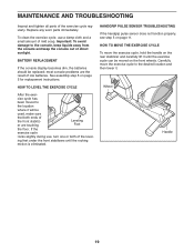
... most console problems are touching Leveling Foot the floor. To clean the exercise cycle, use , turn one or both ends of direct sunlight. Carefully move the exercise cycle, hold the handle on the front wheels. Replace any worn parts immediately. cise cycle has been moved to the location where it . HANDGRIP PULSE SENSOR TROUBLESHOOTING If the handgrip pulse sensor does not function properly, see step 5 on page 5 for replacement instructions...
... most console problems are touching Leveling Foot the floor. To clean the exercise cycle, use , turn one or both ends of direct sunlight. Carefully move the exercise cycle, hold the handle on the front wheels. Replace any worn parts immediately. cise cycle has been moved to the location where it . HANDGRIP PULSE SENSOR TROUBLESHOOTING If the handgrip pulse sensor does not function properly, see step 5 on page 5 for replacement instructions...
English Manual
Page 20
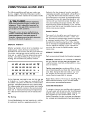
... requires large amounts of your exercise program, do not keep your heart rate in your condition, plan three workouts each week, if desired. WARNING: Before beginning this or any exercise program, consult your "training zone." This is especially important for exercise. The pulse sensor is to exercise with pre-existing health problems. The pulse sensor is to strengthen your training zone as a guide. EXERCISE INTENSITY Whether your goal is...
... requires large amounts of your exercise program, do not keep your heart rate in your condition, plan three workouts each week, if desired. WARNING: Before beginning this or any exercise program, consult your "training zone." This is especially important for exercise. The pulse sensor is to exercise with pre-existing health problems. The pulse sensor is to strengthen your training zone as a guide. EXERCISE INTENSITY Whether your goal is...

English Manual
Page 21
... Front Side Shield Left Front Stabilizer Rear Stabilizer Wheel Right Pedal Strap Leveling Foot Upright Bushing Right Pedal Left Pedal Right Crank Arm Left Crank Arm Left Pedal Strap Left Side Shield Right Side Shield Large Snap Ring Pulley Magnet Crank Steel Washer Crank Bearing Flywheel "C" Magnet Resistance Cable Spring Resistance Motor Idler Right Front Stabilizer Seat Carriage Upper Wire Harness Lower Wire Harness Flywheel Spacer Clamp Reed Switch/Wire 47 1 48 2 49 1 50 2 51 1 52...
... Front Side Shield Left Front Stabilizer Rear Stabilizer Wheel Right Pedal Strap Leveling Foot Upright Bushing Right Pedal Left Pedal Right Crank Arm Left Crank Arm Left Pedal Strap Left Side Shield Right Side Shield Large Snap Ring Pulley Magnet Crank Steel Washer Crank Bearing Flywheel "C" Magnet Resistance Cable Spring Resistance Motor Idler Right Front Stabilizer Seat Carriage Upper Wire Harness Lower Wire Harness Flywheel Spacer Clamp Reed Switch/Wire 47 1 48 2 49 1 50 2 51 1 52...
English Manual
Page 24
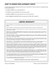
... exercise cycle) • the SERIAL NUMBER of the product (see the front cover of this manual) • the KEY NUMBER and DESCRIPTION of the part(s) (see the front cover of purchase if you . HOW LONG IS IT COVERED-ICON Health & Fitness, Inc. ("ICON"), warrants the product for repair. To help us assist you , without our written authorization or by failure on your proof of this limited warranty...
... exercise cycle) • the SERIAL NUMBER of the product (see the front cover of this manual) • the KEY NUMBER and DESCRIPTION of the part(s) (see the front cover of purchase if you . HOW LONG IS IT COVERED-ICON Health & Fitness, Inc. ("ICON"), warrants the product for repair. To help us assist you , without our written authorization or by failure on your proof of this limited warranty...


