
Owner Manual
Page 1
...N.J. 07446, U.S.A. Integrated Stereo Amplifier A-905X ONKYO CORPORATION Sales & Product Planning Div. : 2-1, Nisshin-cho, Neyagawa-shi, OSAKA 572-8540, JAPAN Tel: 0720-31-8111 Fax: 0720-33-5222 ONKYO U.S.A. Tel: 201-825-7950 Fax: 201-825-8150 E-mail: onkyo@onkyousa.com ONKYO EUROPE ELECTRONICS GmbH Industriestrasse 20... info@onkyo.de ONKYO CHINA LIMITED Units 2102-7, Metroplaza Tower 1, 223 Hing Fong Road, Kwai Chung, N.T., HONG KONG Tel: 852 2429 3118 Fax: 852 2428 9039 ONKYO HOMEPAGE http://www.onkyo.co.jp/ SN 29342717 Printed in Japan Ti 19905-1 Instruction Manual ONKYO INTFGP,...
...N.J. 07446, U.S.A. Integrated Stereo Amplifier A-905X ONKYO CORPORATION Sales & Product Planning Div. : 2-1, Nisshin-cho, Neyagawa-shi, OSAKA 572-8540, JAPAN Tel: 0720-31-8111 Fax: 0720-33-5222 ONKYO U.S.A. Tel: 201-825-7950 Fax: 201-825-8150 E-mail: onkyo@onkyousa.com ONKYO EUROPE ELECTRONICS GmbH Industriestrasse 20... info@onkyo.de ONKYO CHINA LIMITED Units 2102-7, Metroplaza Tower 1, 223 Hing Fong Road, Kwai Chung, N.T., HONG KONG Tel: 852 2429 3118 Fax: 852 2428 9039 ONKYO HOMEPAGE http://www.onkyo.co.jp/ SN 29342717 Printed in Japan Ti 19905-1 Instruction Manual ONKYO INTFGP,...
Owner Manual
Page 2
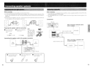
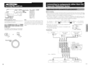
... no built-in amplifier Amplifier Subwoofer 14 15 Connections This unit .1S4C1?-(s-J) .°)_,.c. When connecting a subwoofer with a built-in amplifier 3 O ID C -L'ATOCEssa-SUNEI08:6FTELI, Audio connection cable =CM-- 1--11M3= or Subwoofer Audio connection cable When connecting a subwoofer with an amplifier, connect a separate amplifier to the unit first, then connect the subwoofer to that amplifier. • The SUBWOOFER PRE OUT connector supplies the left and right speakers Before connecting • The load impedance of the speaker cords may become too...
... no built-in amplifier Amplifier Subwoofer 14 15 Connections This unit .1S4C1?-(s-J) .°)_,.c. When connecting a subwoofer with a built-in amplifier 3 O ID C -L'ATOCEssa-SUNEI08:6FTELI, Audio connection cable =CM-- 1--11M3= or Subwoofer Audio connection cable When connecting a subwoofer with an amplifier, connect a separate amplifier to the unit first, then connect the subwoofer to that amplifier. • The SUBWOOFER PRE OUT connector supplies the left and right speakers Before connecting • The load impedance of the speaker cords may become too...
Owner Manual
Page 3
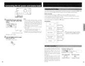
... on the area of another component, that component's AC power cord (mains lead) must be connected in the RI system hookups for a long time, set POWER switch to On. • Leave POWER switch on the 16 rear panel. 13 Make sure that has RI connectors except for the amplifier and receiver) CD player AC outlet connection You can use the unit for RI control operations. • Each component has two RI connectors...
... on the area of another component, that component's AC power cord (mains lead) must be connected in the RI system hookups for a long time, set POWER switch to On. • Leave POWER switch on the 16 rear panel. 13 Make sure that has RI connectors except for the amplifier and receiver) CD player AC outlet connection You can use the unit for RI control operations. • Each component has two RI connectors...
Owner Manual
Page 4
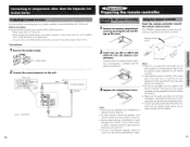
... remote controller. graphic equalizer, surround processor, etc.) to the unit. tion, so that the sound is not to avoid damage from the remote controller. PRE OUT 12 Installing the remote controller batteries / Remove the battery compartment cover by mistake and drain the batteries. • Make sure the audio rack doors do not use the PROCESSOR connectors, reconnect the jumper plugs to them for a long time...
... remote controller. graphic equalizer, surround processor, etc.) to the unit. tion, so that the sound is not to avoid damage from the remote controller. PRE OUT 12 Installing the remote controller batteries / Remove the battery compartment cover by mistake and drain the batteries. • Make sure the audio rack doors do not use the PROCESSOR connectors, reconnect the jumper plugs to them for a long time...
Owner Manual
Page 5
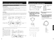
... left channel.Connect white plugs of audio connection cables to L connectors and connect red plugs of audio connection cables to turn it on the unit. If the connection is 230 V model) OUTPUT Tuner OUTPUT CD player REC INPUT PLAY OUTPUT MD recorder 18 11 Insert completely LD player AUDIO OUT Video cassette recorder AUDIO OUT Stereo cassette tape deck REC INPUT PLAY OUTPUT Signal flow a II T1, 'E:C7 ) e. The STANDBY indicator goes off, and the power/ muting lamp above the VOLUME control lights. CY) Ki) LINE-2 LINE-1 TAPE OUT...
... left channel.Connect white plugs of audio connection cables to L connectors and connect red plugs of audio connection cables to turn it on the unit. If the connection is 230 V model) OUTPUT Tuner OUTPUT CD player REC INPUT PLAY OUTPUT MD recorder 18 11 Insert completely LD player AUDIO OUT Video cassette recorder AUDIO OUT Stereo cassette tape deck REC INPUT PLAY OUTPUT Signal flow a II T1, 'E:C7 ) e. The STANDBY indicator goes off, and the power/ muting lamp above the VOLUME control lights. CY) Ki) LINE-2 LINE-1 TAPE OUT...
Owner Manual
Page 6
... by simply turning oft the POWER switch on the A905X to use the clock or Timer function, leave the POWER switch set to decrease the volume. Stereo cassette tape deck (K-505X) or MD recorder (MD105X) (The illustration is selected. this page. • Each component has two RI connectors. INPUT 2 Start playing the source you connect the power cord as shown below , you can turn on the POWER switch on the amplifier A-905X. or INPUT SELECTOR-, VOLUME', If...
... by simply turning oft the POWER switch on the A905X to use the clock or Timer function, leave the POWER switch set to decrease the volume. Stereo cassette tape deck (K-505X) or MD recorder (MD105X) (The illustration is selected. this page. • Each component has two RI connectors. INPUT 2 Start playing the source you connect the power cord as shown below , you can turn on the POWER switch on the amplifier A-905X. or INPUT SELECTOR-, VOLUME', If...
Owner Manual
Page 7
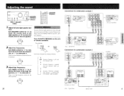
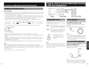
...adds realness to music through the use with compact speakers. BALANCE N 2 Adjust low frequencies. Turn TREBLE control to "+" to attenuate it . this unit (A-905X) .1(7a,r T CM) ,mes V IG f )AI IA OG Th - DIGITAL OUTPUT OPTICAL 1 2 - 1NAl DC DIGITAL INPUT OPTICAL I Adjust left speaker. Press ACOUSTIC PRESENCE on the unit or remote controller. Tuner (T-405X) OUaECI IHIPLA' 0 Ct'%' Cc) (6, O O LINE.2 LINE.I - C D- 11 Ant I=1 CD player (C-705X) or CD changer (C-707CH) Signal flow 0 z 3 I Stereo cassette tape deck (K-505X) Connections for combination...
...adds realness to music through the use with compact speakers. BALANCE N 2 Adjust low frequencies. Turn TREBLE control to "+" to attenuate it . this unit (A-905X) .1(7a,r T CM) ,mes V IG f )AI IA OG Th - DIGITAL OUTPUT OPTICAL 1 2 - 1NAl DC DIGITAL INPUT OPTICAL I Adjust left speaker. Press ACOUSTIC PRESENCE on the unit or remote controller. Tuner (T-405X) OUaECI IHIPLA' 0 Ct'%' Cc) (6, O O LINE.2 LINE.I - C D- 11 Ant I=1 CD player (C-705X) or CD changer (C-707CH) Signal flow 0 z 3 I Stereo cassette tape deck (K-505X) Connections for combination...
Owner Manual
Page 8
... stereo cassette tape deck to "DIRECT", you set to "DIRECT.") Press MUTING button on page 14. • On each component when you make any connections. DIRECT: A signal selected via the Input Selector will reproduce no sound while the headphones are connected. mote controller, the sound wil l be restored. The speakers will bypass the BASS and TREBLE controls. i-Improper connection Insert completely • When you turn it tightly. • Bundling an audio connection cable with the power cord or speaker cord...
... stereo cassette tape deck to "DIRECT", you set to "DIRECT.") Press MUTING button on page 14. • On each component when you make any connections. DIRECT: A signal selected via the Input Selector will reproduce no sound while the headphones are connected. mote controller, the sound wil l be restored. The speakers will bypass the BASS and TREBLE controls. i-Improper connection Insert completely • When you turn it tightly. • Bundling an audio connection cable with the power cord or speaker cord...
Owner Manual
Page 9
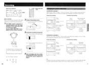
... Input source indicators INPUT SELECTOR oa /► INPUT ""L•iI'Lio n- I Turn INPUT selector clockwise or counterclockwise until the input indicator of the related components for detailed recording operations. INPUT O( ) 2 Prepare the playing source. or r INPUT SELECTOR - MD il-I 1 deck (K-505X) -a 3 3 CD player (C -705X) or CD changer (C-707CH) Amplifier - The CD player is selected. Vertical way stacking Horizontal way stacking Tuner (T-405X) Amplifier -this unit (A-905X) 0 kp I . this unit (A-905X) Tuner (T-405X) Stereo cassette tape deck...
... Input source indicators INPUT SELECTOR oa /► INPUT ""L•iI'Lio n- I Turn INPUT selector clockwise or counterclockwise until the input indicator of the related components for detailed recording operations. INPUT O( ) 2 Prepare the playing source. or r INPUT SELECTOR - MD il-I 1 deck (K-505X) -a 3 3 CD player (C -705X) or CD changer (C-707CH) Amplifier - The CD player is selected. Vertical way stacking Horizontal way stacking Tuner (T-405X) Amplifier -this unit (A-905X) 0 kp I . this unit (A-905X) Tuner (T-405X) Stereo cassette tape deck...
Owner Manual
Page 10
... a music/radio program using the timer. (Refer to the T-405X instruction manual for more information.) • CD Dubbing Simple CD dubbing using a stereo cassette tape deck or MD recorder is possible with the pressing of the control range. • There is some obstruction between the left or right speaker. Combination use independently afterwards. • Direct Change Press the following button on . Connections Connecting to the ONKYO Separate Collection Series components This...
... a music/radio program using the timer. (Refer to the T-405X instruction manual for more information.) • CD Dubbing Simple CD dubbing using a stereo cassette tape deck or MD recorder is possible with the pressing of the control range. • There is some obstruction between the left or right speaker. Combination use independently afterwards. • Direct Change Press the following button on . Connections Connecting to the ONKYO Separate Collection Series components This...
Owner Manual
Page 11
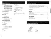
... mV/2 2 kohms Bass control ± 8 dB at 8 ohms, both channels driven 1 kHz, with no more than the Separate Collection Series 11 Connecting speaker systems 14 Connecting the AC power cord (mains lead) 16 Preparations Preparing the remote controller 17 Operation Turning the unit on 18 Choosing the required source 19 Adjusting the sound 20 Source Direct function/Muting/Listening with this unit. UM-3) 24 5 Sulsn woof/ Specifications Table of product...
... mV/2 2 kohms Bass control ± 8 dB at 8 ohms, both channels driven 1 kHz, with no more than the Separate Collection Series 11 Connecting speaker systems 14 Connecting the AC power cord (mains lead) 16 Preparations Preparing the remote controller 17 Operation Turning the unit on 18 Choosing the required source 19 Adjusting the sound 20 Source Direct function/Muting/Listening with this unit. UM-3) 24 5 Sulsn woof/ Specifications Table of product...
Owner Manual
Page 12
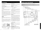
... Onkyo authorized service station. Warranty Claim You can find the serial number on the ment fuse has a rating of the area where this instruction manual is approved by qualified service personnel. 2. GERMANY declare in any doubt, please consult a qualified electrician. NSE SJURCE DIPECI DIRECT A 905X SOURCE DIRECT indicator [21] SOURCE DIRECT selector [21] VOLUME control [19] BALANCE control [20] TREBLE control [20] BASS control [20] PHONES jack [21] POWER ON/OFF switch [16] ACOUSTIC PRESENCE button...
... Onkyo authorized service station. Warranty Claim You can find the serial number on the ment fuse has a rating of the area where this instruction manual is approved by qualified service personnel. 2. GERMANY declare in any doubt, please consult a qualified electrician. NSE SJURCE DIPECI DIRECT A 905X SOURCE DIRECT indicator [21] SOURCE DIRECT selector [21] VOLUME control [19] BALANCE control [20] TREBLE control [20] BASS control [20] PHONES jack [21] POWER ON/OFF switch [16] ACOUSTIC PRESENCE button...
Owner Manual
Page 13
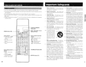
... qualified service personnel. 3 Power-Cord Protection - Wall or Ceiling Mounting - The appliance has been dropped, or the enclosure damaged. 17. -Ls Remote controller • You can control the other RI-connected components with the supplied remote controller. • The remote controller buttons operate in the same way as the buttons on each component with the same indication. • For actual operations, please refer to the Instruction Manual for each component. • Buttons...
... qualified service personnel. 3 Power-Cord Protection - Wall or Ceiling Mounting - The appliance has been dropped, or the enclosure damaged. 17. -Ls Remote controller • You can control the other RI-connected components with the supplied remote controller. • The remote controller buttons operate in the same way as the buttons on each component with the same indication. • For actual operations, please refer to the Instruction Manual for each component. • Buttons...
Owner Manual
Page 14
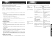
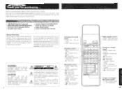
...-Quality Separate Component • WRAT (Wide Range Amp Technology) Circuit • Processor In/Out, Subwoofer Pre Out • Six-audio Source Inputs • Acoustic Presence Circuit Naturally Enhances the Extreme Low Range • Source Direct Function • System Control Remote Controller Memory Preservation This unit does not require memory preservation batteries. The unit must be of sufficient magnitude to constitute a risk of the memory during power failures and...
...-Quality Separate Component • WRAT (Wide Range Amp Technology) Circuit • Processor In/Out, Subwoofer Pre Out • Six-audio Source Inputs • Acoustic Presence Circuit Naturally Enhances the Extreme Low Range • Source Direct Function • System Control Remote Controller Memory Preservation This unit does not require memory preservation batteries. The unit must be of sufficient magnitude to constitute a risk of the memory during power failures and...

