
Owner Manual
Page 1
Please read this manual thoroughly before making connections and plugging in this manual for purchasing the Onkyo AV Receiver. Following the instructions in the unit. Contents Before using Important safeguards 2 Precautions 3 Features 4 Supplied accessories 4 Before using the ... optimum performance and listening enjoyment from your new AV Receiver. Please retain this manual will enable you for future reference. AV Receiver HT-R500 Instruction Manual Thank you to all the sources 26 Enjoying the listening modes 30 Recording a source 33 Remote controller Using the remote ...
Please read this manual thoroughly before making connections and plugging in this manual for purchasing the Onkyo AV Receiver. Following the instructions in the unit. Contents Before using Important safeguards 2 Precautions 3 Features 4 Supplied accessories 4 Before using the ... optimum performance and listening enjoyment from your new AV Receiver. Please retain this manual will enable you for future reference. AV Receiver HT-R500 Instruction Manual Thank you to all the sources 26 Enjoying the listening modes 30 Recording a source 33 Remote controller Using the remote ...

Owner Manual
Page 2
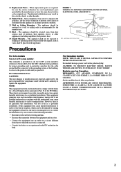
Heed Warnings - Unplug the appliance from the wall outlet before the appliance is grounded so as an improper adjustment of other controls may be equipped with regard to proper grounding of the mast and supporting structure, grounding of antenna-discharge unit, connection to grounding electrodes, and requirements for the appliance during a lightning storm, or when it from touching such power lines or circuits as recommended by placing the appliance on the appliance. 19. Water and Moisture - in wire to its normal operation, E. and the like. 8. Do not place the appliance on...
Heed Warnings - Unplug the appliance from the wall outlet before the appliance is grounded so as an improper adjustment of other controls may be equipped with regard to proper grounding of the mast and supporting structure, grounding of antenna-discharge unit, connection to grounding electrodes, and requirements for the appliance during a lightning storm, or when it from touching such power lines or circuits as recommended by placing the appliance on the appliance. 19. Water and Moisture - in wire to its normal operation, E. and the like. 8. Do not place the appliance on...
Owner Manual
Page 3
Unauthorized substitutions may cause harmful interference to comply with a polarized plug: CAUTION: TO PREVENT ELECTRIC SHOCK, MATCH WIDE BLADE OF PLUG TO WIDE SLOT, FULLY INSERT. The appliance should be situated away from that the cable ground shall be sure the service technician has used replacement parts specified by the manufacturer. 24. FCC Information for User CAUTION: The user changes or modifications not expressly approved by the party responsible for help. NOTE: This equipment has been tested and found to radio communications. However, there is encouraged to try to ...
Unauthorized substitutions may cause harmful interference to comply with a polarized plug: CAUTION: TO PREVENT ELECTRIC SHOCK, MATCH WIDE BLADE OF PLUG TO WIDE SLOT, FULLY INSERT. The appliance should be situated away from that the cable ground shall be sure the service technician has used replacement parts specified by the manufacturer. 24. FCC Information for User CAUTION: The user changes or modifications not expressly approved by the party responsible for help. NOTE: This equipment has been tested and found to radio communications. However, there is encouraged to try to ...
Owner Manual
Page 4
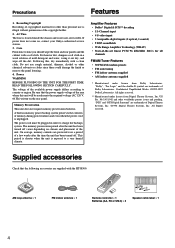
...memory preservation batteries. This period is shorter when the unit is illegal without permission of the area where this , dry immediately with the HT-R500. US Pat. Supplied accessories Check that the power supply voltage of the copyright holder. 2. AC Fuse The fuse is located inside the... THE FOLLOWING SECTION CAREFULLY. The power cord must be used meets the required voltage (AC 120 V, 60 Hz) written on , contact your Onkyo authorized service station. 3. On average, memory contents are trademarks of copyrighted material for all channels FM/AM Tuner Features • 30 FM/AM...
...memory preservation batteries. This period is shorter when the unit is illegal without permission of the area where this , dry immediately with the HT-R500. US Pat. Supplied accessories Check that the power supply voltage of the copyright holder. 2. AC Fuse The fuse is located inside the... THE FOLLOWING SECTION CAREFULLY. The power cord must be used meets the required voltage (AC 120 V, 60 Hz) written on , contact your Onkyo authorized service station. 3. On average, memory contents are trademarks of copyrighted material for all channels FM/AM Tuner Features • 30 FM/AM...

Owner Manual
Page 5
Notes • Do not mix new batteries with the diagram inside the battery compartment. Placing the unit behind such doors may prevent proper remote controller operation. • If there is not to be pressed by mistake and drain the batteries. • Make sure the audio rack doors do not have colored glass. Before using the unit near equipment which uses infrared rays may be used for a long time. • Remove dead batteries immediately to match the + and - Notes • Place the unit away from strong light such as a book) on usage. If the remote controller does not ...
Notes • Do not mix new batteries with the diagram inside the battery compartment. Placing the unit behind such doors may prevent proper remote controller operation. • If there is not to be pressed by mistake and drain the batteries. • Make sure the audio rack doors do not have colored glass. Before using the unit near equipment which uses infrared rays may be used for a long time. • Remove dead batteries immediately to match the + and - Notes • Place the unit away from strong light such as a book) on usage. If the remote controller does not ...
Owner Manual
Page 6
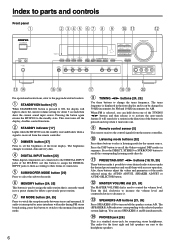
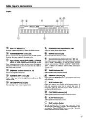
Press the DSP button to recall the Onkyo-original DSP modes in the direction of ...SPEAKERS A/B to turn on/off the display, disables control functions. 2 STANDBY indicator [17] Lights when the HT-R500 is in the standby state and flashes when a signal is interrupted or noise interferes with audio during FM stereo... to the monaural reception mode. 8 TUNING ™/£ buttons [24, 25] Use these buttons adjust the values and parameters of the HT-R500, use SPEAKERS A and B simultaneously. ! This state turns off the speaker system A/B. Index to parts and controls Front panel 1 2 345...
Press the DSP button to recall the Onkyo-original DSP modes in the direction of ...SPEAKERS A/B to turn on/off the display, disables control functions. 2 STANDBY indicator [17] Lights when the HT-R500 is in the standby state and flashes when a signal is interrupted or noise interferes with audio during FM stereo... to the monaural reception mode. 8 TUNING ™/£ buttons [24, 25] Use these buttons adjust the values and parameters of the HT-R500, use SPEAKERS A and B simultaneously. ! This state turns off the speaker system A/B. Index to parts and controls Front panel 1 2 345...
Owner Manual
Page 7
b MUTING indicator [26] Flashes when the mute function is started by pressing the FM MODE button. h SLEEP indicator [27] Lights up when a radio station is received. d TUNED indicator [24] Lights up when the sleep timer is selected, it shows the current input source and the listening mode. 7 Index to parts and controls Display ab c eg df h i @ DISPLAY button [27] Each time you press the DISPLAY button, the display changes. # AUDIO SELECTOR button [28] Press to adjust bass, treble, late night function and cinema filter function setting. & VIDEO 3 INPUT jacks [33] For ...
b MUTING indicator [26] Flashes when the mute function is started by pressing the FM MODE button. h SLEEP indicator [27] Lights up when a radio station is received. d TUNED indicator [24] Lights up when the sleep timer is selected, it shows the current input source and the listening mode. 7 Index to parts and controls Display ab c eg df h i @ DISPLAY button [27] Each time you press the DISPLAY button, the display changes. # AUDIO SELECTOR button [28] Press to adjust bass, treble, late night function and cinema filter function setting. & VIDEO 3 INPUT jacks [33] For ...
Owner Manual
Page 8
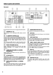
... FRONT SPEAKERS A/B [13] Speaker terminals are provided for the front left and surround right speakers. 5 AC OUTLET [11] The HT-R500 is supplied through the HT-R500. This output is for connecting an active subwoofer. 8 CD IN [10] Connect the output terminal on the CD player to the...(REMOTE CONTROL) [16] Connect the Onkyo components that have z connectors such as well. 6 DIGITAL INPUT OPTICAL 1, 2, COAXIAL [10, 11] These are the digital audio inputs. Connect the output terminals of the video cassette recorder to the VIDEO 1 IN L/R jacks on the HT-R500 and the input terminals (REC) to...
... FRONT SPEAKERS A/B [13] Speaker terminals are provided for the front left and surround right speakers. 5 AC OUTLET [11] The HT-R500 is supplied through the HT-R500. This output is for connecting an active subwoofer. 8 CD IN [10] Connect the output terminal on the CD player to the...(REMOTE CONTROL) [16] Connect the Onkyo components that have z connectors such as well. 6 DIGITAL INPUT OPTICAL 1, 2, COAXIAL [10, 11] These are the digital audio inputs. Connect the output terminals of the video cassette recorder to the VIDEO 1 IN L/R jacks on the HT-R500 and the input terminals (REC) to...
Owner Manual
Page 9
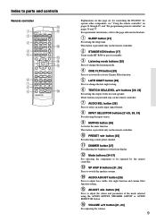
... Press to change the late night setting. 6 TEST/CH SEL/LEVEL 5/∞ buttons [20, 28] For setting the output levels for controlling the HT-R500. This button is provided only on pages 36 and 37. AUDIO ADJUST button [29] Press to adjust bass, treble, late night function and cinema ...2/3 button [29] Press to switch the speaker systems. ! This button is provided only on the remote controller. 2 STANDBY/ON button [17] Turns on the HT-R500 or put it in brackets. 1 SLEEP button [27] For setting the sleep time. DIMMER button [27] For adjusting the brightness of the front display. = Mode...
... Press to change the late night setting. 6 TEST/CH SEL/LEVEL 5/∞ buttons [20, 28] For setting the output levels for controlling the HT-R500. This button is provided only on pages 36 and 37. AUDIO ADJUST button [29] Press to adjust bass, treble, late night function and cinema ...2/3 button [29] Press to switch the speaker systems. ! This button is provided only on the remote controller. 2 STANDBY/ON button [17] Turns on the HT-R500 or put it in brackets. 1 SLEEP button [27] For setting the sleep time. DIMMER button [27] For adjusting the brightness of the front display. = Mode...
Owner Manual
Page 10
... "Setting the digital inputs" on page 22. • The TAPE OUT jack does not output the signal input from VIDEO IN is sent to the HT-R500 in the power cord until all plugs and connectors securely. To connect the digital output to the OPTICAL 2 or COAXIAL input jack of as each...
... "Setting the digital inputs" on page 22. • The TAPE OUT jack does not output the signal input from VIDEO IN is sent to the HT-R500 in the power cord until all plugs and connectors securely. To connect the digital output to the OPTICAL 2 or COAXIAL input jack of as each...
Owner Manual
Page 11
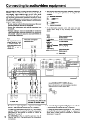
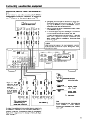
... player has both 5.1 channel audio outputs and 2 channel audio outputs, and you want to connect the DVD player only using the FRONT L/R jacks on the HT-R500, use the 2 channel audio output jacks on the DVD player. • If the DVD player only has the 2 channel audio outputs, connect it to the... your component(s), the amplifier, and your TV) DVD player or component with AC-3RF output, connect via an AC-3RF demodulator to one of the HT-R500's DIGITAL INPUT terminals. connected to the VIDEO 1 or VIDEO 2 jacks to the COAXIAL, OPTICAL 1 or 2 input jack of this R time.
... player has both 5.1 channel audio outputs and 2 channel audio outputs, and you want to connect the DVD player only using the FRONT L/R jacks on the HT-R500, use the 2 channel audio output jacks on the DVD player. • If the DVD player only has the 2 channel audio outputs, connect it to the... your component(s), the amplifier, and your TV) DVD player or component with AC-3RF output, connect via an AC-3RF demodulator to one of the HT-R500's DIGITAL INPUT terminals. connected to the VIDEO 1 or VIDEO 2 jacks to the COAXIAL, OPTICAL 1 or 2 input jack of this R time.

Owner Manual
Page 12
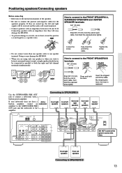
The FRONT SPEAKERS A system is to be placed in the main room, and the FRONT SPEAKERS B system is properly distributed to the connected speakers in order to the terminal having the same color as Dolby surround and DTS surround. The placement of the speakers varies depending on the size of each color to the speaker cable for the corresponding terminal and connect the speaker cable to experience the best of Surround sound. If a center speaker or subwoofer is not connected, the sound from the unused channel is to this unit are colored as follows. Place the left and right speakers, ...
The FRONT SPEAKERS A system is to be placed in the main room, and the FRONT SPEAKERS B system is properly distributed to the connected speakers in order to the terminal having the same color as Dolby surround and DTS surround. The placement of the speakers varies depending on the size of each color to the speaker cable for the corresponding terminal and connect the speaker cable to experience the best of Surround sound. If a center speaker or subwoofer is not connected, the sound from the unused channel is to this unit are colored as follows. Place the left and right speakers, ...
Owner Manual
Page 13
...for the speakers properly. Tighten the screw. By releasing the twist the exposed lever, the lever is wires tightly. NO! Doing so may damage the HT-R500. • To prevent damage to circuits, never short-circuit the positive (+) and negative (-) speaker wires. Loosen the screw. R L R NO! ...Fully insert the end of each cable, then twist the exposed wires tightly. • Do not connect more than 6 Ω may damage the HT-R500. • When you are mixed up, the left speakers Connecting to SPEAKERS B 13 How to connect to monaural (mono) sound, a single ...
...for the speakers properly. Tighten the screw. By releasing the twist the exposed lever, the lever is wires tightly. NO! Doing so may damage the HT-R500. • To prevent damage to circuits, never short-circuit the positive (+) and negative (-) speaker wires. Loosen the screw. R L R NO! ...Fully insert the end of each cable, then twist the exposed wires tightly. • Do not connect more than 6 Ω may damage the HT-R500. • When you are mixed up, the left speakers Connecting to SPEAKERS B 13 How to connect to monaural (mono) sound, a single ...
Owner Manual
Page 14
... IN FRONT SURR CENTER L L R VIDEO 2 VIDEO 1 R DVD SUB WOOFER FRONT SPEAKERS A FRONT SPEAKERS B SURROUND SPEAKERS L L L R R R CENTER SPEAKER AC OUTLET 1 Strip away the insulation from the HT-R500, televisions, speaker cables, and power cords. Set it in the direction and position where you receive signals clearly.
... IN FRONT SURR CENTER L L R VIDEO 2 VIDEO 1 R DVD SUB WOOFER FRONT SPEAKERS A FRONT SPEAKERS B SURROUND SPEAKERS L L L R R R CENTER SPEAKER AC OUTLET 1 Strip away the insulation from the HT-R500, televisions, speaker cables, and power cords. Set it in the direction and position where you receive signals clearly.

Owner Manual
Page 15
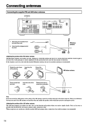
Connecting antennas Connecting an FM outdoor antenna If the FM reception is not very clear with each other. Follow item 14 of the indoor FM antenna. Follow item 14 of lightning and electrical shock, grounding is dangerous to put the antenna close to power lines. Directional linkage type splitter To AV Receiver To TV (or VCR) 15 If you install the outdoor antenna. Leave the supplied AM indoor antenna connected. FM outdoor antenna AM FM 75 Connecting an AM outdoor antenna An outdoor antenna will be more effective if it well away from power lines, transformers, etc. • ...
Connecting antennas Connecting an FM outdoor antenna If the FM reception is not very clear with each other. Follow item 14 of the indoor FM antenna. Follow item 14 of lightning and electrical shock, grounding is dangerous to put the antenna close to power lines. Directional linkage type splitter To AV Receiver To TV (or VCR) 15 If you install the outdoor antenna. Leave the supplied AM indoor antenna connected. FM outdoor antenna AM FM 75 Connecting an AM outdoor antenna An outdoor antenna will be more effective if it well away from power lines, transformers, etc. • ...
Owner Manual
Page 16
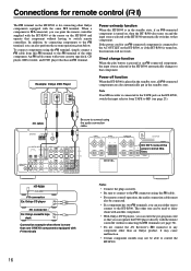
...not connect the AV Receiver's z connector to any component other one ONKYO components equipped with the remote controller without having to switch remote controllers. HT-R500 REMOTE CONTROL z connector Ex: Onkyo CD player z connector Ex: Onkyo cassette tape deck Connection example when there is more than one can... to the AC OUTLET on the HT-R500, or if the HT-R500 is turned on, this function will not work. When a component is turned on, then the HT-R500 also turns on /ready function When the HT-R500 is in the standby state. Example: Onkyo DVD Player REMOTE CONTROL COAXIAL DIGITAL OUTPUT...
...not connect the AV Receiver's z connector to any component other one ONKYO components equipped with the remote controller without having to switch remote controllers. HT-R500 REMOTE CONTROL z connector Ex: Onkyo CD player z connector Ex: Onkyo cassette tape deck Connection example when there is more than one can... to the AC OUTLET on the HT-R500, or if the HT-R500 is turned on, this function will not work. When a component is turned on, then the HT-R500 also turns on /ready function When the HT-R500 is in the standby state. Example: Onkyo DVD Player REMOTE CONTROL COAXIAL DIGITAL OUTPUT...
Owner Manual
Page 17
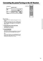
... indicator lights up. 2. Note To turn off . The AV Receiver turns on a different circuit. 1. Press STANDBY/ON. If this happens, use a wall outlet on . The HT-R500 enters standby mode. The ON indicator and display on the AV Receiver may cause a momentary power surge, which might interfere with other electrical equipment such...
... indicator lights up. 2. Note To turn off . The AV Receiver turns on a different circuit. 1. Press STANDBY/ON. If this happens, use a wall outlet on . The HT-R500 enters standby mode. The ON indicator and display on the AV Receiver may cause a momentary power surge, which might interfere with other electrical equipment such...
Owner Manual
Page 18
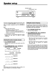
When the button is displayed. 2. Headphones are relatively large (when they cannot reproduce low frequencies sufficiently): 120 Hz • When other speakers (front, center and surround). 1. Press SPEAKER ADJUST. Front left Surround right Display and number of speaker channels Speaker 5ch Speaker 2ch Speaker 3ch Speaker 4ch Note The listening mode will be done if; - Also listen to the actual sound and set to the high position (120 Hz) if you feel that the sound from 80 Hz, 100 Hz and 120 Hz. Press PRESET/ADJUST ™/£ repeatedly to select the crossover ...
When the button is displayed. 2. Headphones are relatively large (when they cannot reproduce low frequencies sufficiently): 120 Hz • When other speakers (front, center and surround). 1. Press SPEAKER ADJUST. Front left Surround right Display and number of speaker channels Speaker 5ch Speaker 2ch Speaker 3ch Speaker 4ch Note The listening mode will be done if; - Also listen to the actual sound and set to the high position (120 Hz) if you feel that the sound from 80 Hz, 100 Hz and 120 Hz. Press PRESET/ADJUST ™/£ repeatedly to select the crossover ...

Owner Manual
Page 19
Assume that the distance from 0 to 15 ms. 19 For example, when (L) is 16 feet (5 meters) and (L1) is 13 feet (4 meters), (L) - (L1) = 16 - 13 = 3 feet / 5 - 4 = 1 meter Since the closest value to 3 feet (1 meter) in the table below is 3/0.9 (ft/m), the center delay time to be set is 10. 1. For example, when (L) is 16 feet (5 meters) and (L2) is 6 feet (2 meters), (L) - (L2) = 16 - 6 = 10 feet / 5 - 2 = 3 meters Since the value of 10 feet (3 meters) is found in the 11th line in the table below , the surround delay time to be set is (L2). Press PRESET/ADJUST ™/£ ...
Assume that the distance from 0 to 15 ms. 19 For example, when (L) is 16 feet (5 meters) and (L1) is 13 feet (4 meters), (L) - (L1) = 16 - 13 = 3 feet / 5 - 4 = 1 meter Since the closest value to 3 feet (1 meter) in the table below is 3/0.9 (ft/m), the center delay time to be set is 10. 1. For example, when (L) is 16 feet (5 meters) and (L2) is 6 feet (2 meters), (L) - (L2) = 16 - 6 = 10 feet / 5 - 2 = 3 meters Since the value of 10 feet (3 meters) is found in the 11th line in the table below , the surround delay time to be set is (L2). Press PRESET/ADJUST ™/£ ...
Owner Manual
Page 20
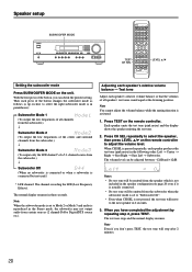
Test tone Adjust each speaker produces the test tone (pink noise) in parentheses): → Subwoofer Mode 1 (To output the low frequencies of a 5.1-channel source from the subwoofer.) ↓ Subwoofer Off (When no subwoofer is connected or when a subwoofer is actually connected. • No test tone will be adjusted between -12dB and +12dB. When CH SEL is pressed repeatedly, each speaker's relative volume balance so that the volumes of all channels from the subwoofer.) ↓ Subwoofer Mode 2 (To output the low frequencies of the center and surround channels from certain sources ...
Test tone Adjust each speaker produces the test tone (pink noise) in parentheses): → Subwoofer Mode 1 (To output the low frequencies of a 5.1-channel source from the subwoofer.) ↓ Subwoofer Off (When no subwoofer is connected or when a subwoofer is actually connected. • No test tone will be adjusted between -12dB and +12dB. When CH SEL is pressed repeatedly, each speaker's relative volume balance so that the volumes of all channels from the subwoofer.) ↓ Subwoofer Mode 2 (To output the low frequencies of the center and surround channels from certain sources ...
