
Owner Manual
Page 4
...can handle the specified input power when used in the upright vertical position only. For European Models Declaration of Conformity We, ONKYO EUROPE ELECTRONICS GmbH LIEGNITZERSTRASSE 6, 82194 GROEBENZELL, GERMANY declare in own responsibility, that are coloured in humid places, such as EN60065, ...64257;er, bathroom, or kitchen. • Do not put it in locations subject to direct sunlight or in accordance with the following signals are placed nearby. GROEBENZELL, GERMANY K. This normally activates the degaussing function, which is in the mains lead are free from an ...
...can handle the specified input power when used in the upright vertical position only. For European Models Declaration of Conformity We, ONKYO EUROPE ELECTRONICS GmbH LIEGNITZERSTRASSE 6, 82194 GROEBENZELL, GERMANY declare in own responsibility, that are coloured in humid places, such as EN60065, ...64257;er, bathroom, or kitchen. • Do not put it in locations subject to direct sunlight or in accordance with the following signals are placed nearby. GROEBENZELL, GERMANY K. This normally activates the degaussing function, which is in the mains lead are free from an ...
Owner Manual
Page 10
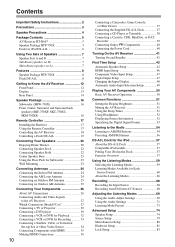
... 24 Connecting an Outdoor FM Antenna 25 Connecting an Outdoor AM Antenna 25 Connecting Your Components 26 About AV Connections 26 Connecting Audio and Video Signals to the AV Receiver 27 Which Connections Should I Use 27 Connecting a TV or Projector 29 Connecting a DVD player 30 Connecting a VCR ... the Supplied DS-A1L Dock 37 Connecting a CD Player or Turntable 38 Connecting a Cassette, CDR, MiniDisc, or DAT Recorder 39 Connecting Onkyo Components 40 Connecting the Power Cord 40 Turning On the AV Receiver 41 Turning On and Standby 41 First Time Setup 42 Automatic Speaker Setup...
... 24 Connecting an Outdoor FM Antenna 25 Connecting an Outdoor AM Antenna 25 Connecting Your Components 26 About AV Connections 26 Connecting Audio and Video Signals to the AV Receiver 27 Which Connections Should I Use 27 Connecting a TV or Projector 29 Connecting a DVD player 30 Connecting a VCR ... the Supplied DS-A1L Dock 37 Connecting a CD Player or Turntable 38 Connecting a Cassette, CDR, MiniDisc, or DAT Recorder 39 Connecting Onkyo Components 40 Connecting the Power Cord 40 Turning On the AV Receiver 41 Turning On and Standby 41 First Time Setup 42 Automatic Speaker Setup...
Owner Manual
Page 12
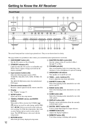
...deleting radio presets. D Remote-control sensor (17) M MOVIE/TV button (59) Selects the listening modes intended for use with the setup menus. Receives control signals from the remote controller. G TUNING, PRESET, Arrow, and ENTER buttons When AM or FM is selected, the TUNING [ ] [ ] buttons are used ...to select and set A and B on Standby and flashes while a signal is also used to input selectors. The page numbers in parentheses show where you can find the main explanation for use with music. Sets...
...deleting radio presets. D Remote-control sensor (17) M MOVIE/TV button (59) Selects the listening modes intended for use with the setup menus. Receives control signals from the remote controller. G TUNING, PRESET, Arrow, and ENTER buttons When AM or FM is selected, the TUNING [ ] [ ] buttons are used ...to select and set A and B on Standby and flashes while a signal is also used to input selectors. The page numbers in parentheses show where you can find the main explanation for use with music. Sets...
Owner Manual
Page 13
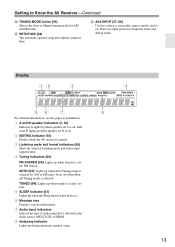
... on. 2 MUTING indicator (51) Flashes while the AV receiver is muted. 3 Listening mode and format indicators (59) Show the selected listening mode and audio input signal format. 4 Tuning indicators (54) FM STEREO (54): Lights up when speaker set . 6 Message area Displays various information. 7 Audio input indicators Indicate the type of audio...
... on. 2 MUTING indicator (51) Flashes while the AV receiver is muted. 3 Listening mode and format indicators (59) Show the selected listening mode and audio input signal format. 4 Tuning indicators (54) FM STEREO (54): Lights up when speaker set . 6 Message area Displays various information. 7 Audio input indicators Indicate the type of audio...
Owner Manual
Page 15
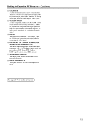
... audio input jacks for connecting speaker set B. There are S-Video and composite video input and output jacks for connecting the video signal, and there are for connecting the audio signal. There are analog audio input jacks for connecting a component with a 5.1/7.1-channel analog audio output, such as a VCR or ...DVR, can be connected to Know the AV Receiver-Continued M CBL/SAT IN A cable or satellite receiver can be connected here for connecting the video signal. N VCR/DVR IN/OUT A video component, such as a DVD player, DVD-Audio or SACD-capable player, or an MPEG decoder. See ...
... audio input jacks for connecting speaker set B. There are S-Video and composite video input and output jacks for connecting the video signal, and there are for connecting the audio signal. There are analog audio input jacks for connecting a component with a 5.1/7.1-channel analog audio output, such as a VCR or ...DVR, can be connected to Know the AV Receiver-Continued M CBL/SAT IN A cable or satellite receiver can be connected here for connecting the video signal. N VCR/DVR IN/OUT A video component, such as a DVD player, DVD-Audio or SACD-capable player, or an MPEG decoder. See ...
Owner Manual
Page 16
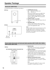
...fication. If the Auto Standby function does not work reliably, try slightly increasing or decreasing the subwoofer output level on when the input signal exceeds a certain level. To AC outlet 23 Front, Center, Surround, and Surround back speakers (SKF-750XF, SKC-750XC, SKM-750XS, ...ON indicator Red: Subwoofer in standby mode Blue: Subwoofer on With the Auto Standby function, the SKW-750X automatically turns on when an input signal is used to attach the speaker either horizontally or vertically to a speaker mount or bracket. 16 Note: Use commercially available 1/4" screws to ...
...fication. If the Auto Standby function does not work reliably, try slightly increasing or decreasing the subwoofer output level on when the input signal exceeds a certain level. To AC outlet 23 Front, Center, Surround, and Surround back speakers (SKF-750XF, SKC-750XC, SKM-750XS, ...ON indicator Red: Subwoofer in standby mode Blue: Subwoofer on With the Auto Standby function, the SKW-750X automatically turns on when an input signal is used to attach the speaker either horizontally or vertically to a speaker mount or bracket. 16 Note: Use commercially available 1/4" screws to ...
Owner Manual
Page 24
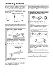
... is for use the tuner. Once your AV receiver, TV, speaker cables, and power cords. Thumbtacks, etc. The AV receiver won't pick up any radio signals without any antenna connected, so you don't injure yourself when using it with the supplied indoor FM antenna, try using thumbtacks. Make sure that the...
... is for use the tuner. Once your AV receiver, TV, speaker cables, and power cords. Thumbtacks, etc. The AV receiver won't pick up any radio signals without any antenna connected, so you don't injure yourself when using it with the supplied indoor FM antenna, try using thumbtacks. Make sure that the...

Owner Manual
Page 26
...S-Video cable Composite video cable Y Y PB CB/PB PR CR/PR S V Component video separates the luminance (Y) and color difference signals (PR, PB), providing the best picture quality. (Some TV manufacturers label their component video jacks slightly differently.) S-Video separates the luminance and color... signals and provides better picture quality than composite video. It's the most common connection format for analog audio and can be found ...
...S-Video cable Composite video cable Y Y PB CB/PB PR CR/PR S V Component video separates the luminance (Y) and color difference signals (PR, PB), providing the best picture quality. (Some TV manufacturers label their component video jacks slightly differently.) S-Video separates the luminance and color... signals and provides better picture quality than composite video. It's the most common connection format for analog audio and can be found ...
Owner Manual
Page 27
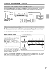
... or COAXIAL input, you must make an audio connection and a video connection. DVD player, etc. You can switch the audio and video signals simultaneously simply by your DVD player and other components. Use the following audio connection formats: analog, optical, coaxial, analog multichannel, or HDMI....format, bear in the following order of AV equipment. The format you must assign that the AV receiver does not convert digital input signals for hookup details) Which Connections Should I Use? For video components, you choose will be connected to an optical or coaxial digital ...
... or COAXIAL input, you must make an audio connection and a video connection. DVD player, etc. You can switch the audio and video signals simultaneously simply by your DVD player and other components. Use the following audio connection formats: analog, optical, coaxial, analog multichannel, or HDMI....format, bear in the following order of AV equipment. The format you must assign that the AV receiver does not convert digital input signals for hookup details) Which Connections Should I Use? For video components, you choose will be connected to an optical or coaxial digital ...

Owner Manual
Page 28
...Video, and component video outputs pass through the AV receiver as shown, with composite video, SVideo, and component video sources all being present. If signals are . AV receiver Composite S-Video Component IN Composite MONITOR OUT S-Video Component TV, projector, etc. HDMI HDMI HDMI HDMI The onscreen setup ...if a component video input is assigned to the input selector, that input to an input selector (see pages 46 and 47). In the Signal Selection Example shown on a TV that is connected to the composite video or S-Video MONITOR OUT, or the COMPONENT VIDEO OUT, use the...
...Video, and component video outputs pass through the AV receiver as shown, with composite video, SVideo, and component video sources all being present. If signals are . AV receiver Composite S-Video Component IN Composite MONITOR OUT S-Video Component TV, projector, etc. HDMI HDMI HDMI HDMI The onscreen setup ...if a component video input is assigned to the input selector, that input to an input selector (see pages 46 and 47). In the Signal Selection Example shown on a TV that is connected to the composite video or S-Video MONITOR OUT, or the COMPONENT VIDEO OUT, use the...

Owner Manual
Page 29
... ( a , b , or c ), and then make the connection. Connection A B C a b c AV receiver COMPONENT VIDEO OUT MONITOR OUT S MONITOR OUT V CBL/SAT IN L/R DIGITAL IN COAXIAL 2 DIGITAL IN OPTICAL 1 Signal flow TV Component video input S-Video input Composite video input Analog audio L/R output Digital coaxial output Digital optical output Picture quality Best Better Standard...
... ( a , b , or c ), and then make the connection. Connection A B C a b c AV receiver COMPONENT VIDEO OUT MONITOR OUT S MONITOR OUT V CBL/SAT IN L/R DIGITAL IN COAXIAL 2 DIGITAL IN OPTICAL 1 Signal flow TV Component video input S-Video input Composite video input Analog audio L/R output Digital coaxial output Digital optical output Picture quality Best Better Standard...

Owner Manual
Page 30
Connection A B C a b c AV receiver COMPONENT VIDEO IN 1 DVD IN S DVD IN V DVD IN FRONT L/R DIGITAL IN COAXIAL 1 DIGITAL IN OPTICAL 1 Signal flow DVD player Component video output S-Video output Composite video output Analog audio L/R output Digital coaxial output Digital optical output Picture quality Best Better ...
Connection A B C a b c AV receiver COMPONENT VIDEO IN 1 DVD IN S DVD IN V DVD IN FRONT L/R DIGITAL IN COAXIAL 1 DIGITAL IN OPTICAL 1 Signal flow DVD player Component video output S-Video output Composite video output Analog audio L/R output Digital coaxial output Digital optical output Picture quality Best Better ...

Owner Manual
Page 32
... VCR or DVR 32 Connection A B C a b c b c AV receiver COMPONENT VIDEO IN 2 VCR/DVR IN S VCR/DVR IN V VCR/DVR IN L/R DIGITAL IN COAXIAL 2 DIGITAL IN OPTICAL 1 Signal flow VCR or DVR Component video output S-Video output Composite video output Analog audio L/R output Digital coaxial output Digital optical output Picture quality Best...
... VCR or DVR 32 Connection A B C a b c b c AV receiver COMPONENT VIDEO IN 2 VCR/DVR IN S VCR/DVR IN V VCR/DVR IN L/R DIGITAL IN COAXIAL 2 DIGITAL IN OPTICAL 1 Signal flow VCR or DVR Component video output S-Video output Composite video output Analog audio L/R output Digital coaxial output Digital optical output Picture quality Best...

Owner Manual
Page 33
... OUT S jack. Step 2: Audio Connection Make the audio connection a . Likewise, video signals connected to the VCR/DVR OUT S jack. 33 Connection A B a AV receiver VCR/DVR OUT S VCR/DVR... OUT V VCR/DVR OUT L/R Signal flow ⇒ ⇒ ⇒ VCR or DVD recorder S-Video input Composite video input Audio L/R input... IN IN IN FRONT SURR CENTER SURR BACK L SURR BACK SPEAKERS Bi-AMP for details. • Video signals connected to the recording VCR/DVR's audio and video inputs. So if your source TV or VCR is connected...
... OUT S jack. Step 2: Audio Connection Make the audio connection a . Likewise, video signals connected to the VCR/DVR OUT S jack. 33 Connection A B a AV receiver VCR/DVR OUT S VCR/DVR... OUT V VCR/DVR OUT L/R Signal flow ⇒ ⇒ ⇒ VCR or DVD recorder S-Video input Composite video input Audio L/R input... IN IN IN FRONT SURR CENTER SURR BACK L SURR BACK SPEAKERS Bi-AMP for details. • Video signals connected to the recording VCR/DVR's audio and video inputs. So if your source TV or VCR is connected...

Owner Manual
Page 34
...-top box, etc. 34 Connection A B C a b c AV receiver COMPONENT VIDEO IN 2 CBL/SAT IN S CBL/SAT IN V CBL/SAT IN L/R DIGITAL IN COAXIAL 2 DIGITAL IN OPTICAL 1 Signal flow Video source Component video output S-Video output Composite video output Analog audio L/R output Digital coaxial output Digital optical output Picture quality Best Better...
...-top box, etc. 34 Connection A B C a b c AV receiver COMPONENT VIDEO IN 2 CBL/SAT IN S CBL/SAT IN V CBL/SAT IN L/R DIGITAL IN COAXIAL 2 DIGITAL IN OPTICAL 1 Signal flow Video source Component video output S-Video output Composite video output Analog audio L/R output Digital coaxial output Digital optical output Picture quality Best Better...

Owner Manual
Page 35
... industry's requirements for a digital connectivity specification for high-performance PCs and digital displays. 35 The HDMI video stream (i.e., video signal) is a new digital interface standard for connecting TVs, projectors, DVD players, set by the DDWG*3 in no picture.) The AV ...and requires a HDCP-compatible device to display the encrypted video. *3 DDWG (Digital Display Working Group): Led by Intel for digital video signals. Use a commercially available HDMI cable (supplied with some components) to connect the AV receiver's HDMI OUT to connect AV components. Until ...
... industry's requirements for a digital connectivity specification for high-performance PCs and digital displays. 35 The HDMI video stream (i.e., video signal) is a new digital interface standard for connecting TVs, projectors, DVD players, set by the DDWG*3 in no picture.) The AV ...and requires a HDCP-compatible device to display the encrypted video. *3 DDWG (Digital Display Working Group): Led by Intel for digital video signals. Use a commercially available HDMI cable (supplied with some components) to connect the AV receiver's HDMI OUT to connect AV components. Until ...

Owner Manual
Page 36
... setting to On (see page 82). If the picture is poor or there's no sound or the sound may be distorted. • The HDMI audio signal (sampling rate, bit length, etc.) may be restricted by the HDMI OUT, unless the Audio TV Out setting is set to a different input source, the... AV receiver may produce no sound from a component connected via HDMI, check its setup. In addition, video signals from the HDMI source component can be connected by the HDMI IN jacks through the AV receiver, you 'll need to make a separate connection for...
... setting to On (see page 82). If the picture is poor or there's no sound or the sound may be distorted. • The HDMI audio signal (sampling rate, bit length, etc.) may be restricted by the HDMI OUT, unless the Audio TV Out setting is set to a different input source, the... AV receiver may produce no sound from a component connected via HDMI, check its setup. In addition, video signals from the HDMI source component can be connected by the HDMI IN jacks through the AV receiver, you 'll need to make a separate connection for...

Owner Manual
Page 37
... MIC AUX INPUT VIDEO L AUDIO R A AUX INPUT VIDEO L AUDIO R OUT VIDEO OUT Camcorder, game console, etc. Connection A a AV receiver AUX INPUT VIDEO AUX INPUT L-AUDIO-R Signal flow ⇐ ⇐ Camcorder or console Composite video output Analog audio L/R output Connecting the Supplied DS-A1L Dock DIGITAL IN 1 (DVD) COAXIAL 2 (CBL/SAT...
... MIC AUX INPUT VIDEO L AUDIO R A AUX INPUT VIDEO L AUDIO R OUT VIDEO OUT Camcorder, game console, etc. Connection A a AV receiver AUX INPUT VIDEO AUX INPUT L-AUDIO-R Signal flow ⇐ ⇐ Camcorder or console Composite video output Analog audio L/R output Connecting the Supplied DS-A1L Dock DIGITAL IN 1 (DVD) COAXIAL 2 (CBL/SAT...

Owner Manual
Page 38
... L R Phono preamp AUDIO OUTPUT L R AUDIO INPUT L R ■ Turntable with an MC (Moving Coil) cartridge. Connection a b c AV receiver CD IN L/R DIGITAL IN COAXIAL 2 DIGITAL IN OPTICAL 2 Signal flow ⇐ ⇐ ⇐ CD or turntable Analog audio L/R output Digital coaxial output Digital optical output ■ Turntable (MM) with no Phono Preamp Built...
... L R Phono preamp AUDIO OUTPUT L R AUDIO INPUT L R ■ Turntable with an MC (Moving Coil) cartridge. Connection a b c AV receiver CD IN L/R DIGITAL IN COAXIAL 2 DIGITAL IN OPTICAL 2 Signal flow ⇐ ⇐ ⇐ CD or turntable Analog audio L/R output Digital coaxial output Digital optical output ■ Turntable (MM) with no Phono Preamp Built...

Owner Manual
Page 39
...; To connect the recorder digitally for playback, use connections a and b , or a and c . Connection a b c AV receiver TAPE IN L/R TAPE OUT L/R DIGITAL IN COAXIAL 2 DIGITAL IN OPTICAL 2 Signal flow Cassette, CDR, MD, or DAT recorder Analog audio L/R output Analog audio L/R input Digital coaxial output Digital optical output 39 Connecting Your Components-Continued...
...; To connect the recorder digitally for playback, use connections a and b , or a and c . Connection a b c AV receiver TAPE IN L/R TAPE OUT L/R DIGITAL IN COAXIAL 2 DIGITAL IN OPTICAL 2 Signal flow Cassette, CDR, MD, or DAT recorder Analog audio L/R output Analog audio L/R input Digital coaxial output Digital optical output 39 Connecting Your Components-Continued...
