Owner Manual
Page 1
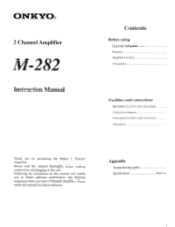
... making connections and plugging in this manual for purchasing the Onkyo 2 Channel Amplifier. Please retain this manual will enable you for future reference. ONKYO® 2 Channel Amplifier -282 Instruction Manual Contents Before using Important Safeguards Features Supplied accessory Precautions Facilities and connections Rear panel facilities and connections Connection diagram Front panel facilities and connections Operations Thank you to obtain optimum performance and listening enjoyment from your new 2 Channel Amplifier. Appendix Troubleshooting guide Specifications Back...
... making connections and plugging in this manual for purchasing the Onkyo 2 Channel Amplifier. Please retain this manual will enable you for future reference. ONKYO® 2 Channel Amplifier -282 Instruction Manual Contents Before using Important Safeguards Features Supplied accessory Precautions Facilities and connections Rear panel facilities and connections Connection diagram Front panel facilities and connections Operations Thank you to obtain optimum performance and listening enjoyment from your new 2 Channel Amplifier. Appendix Troubleshooting guide Specifications Back...
Owner Manual
Page 2
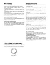
... Hz) written on the rear panel of mild detergent and water, wring it out dry, and wipe off the M-282 via a signal input to the AUDIO IN jacks or 12V TRIGGER IN jack. If the power does not come on and off the dirt. Following this unit. Care From time to time you can turn on , contact your Onkyo authorized service station. 4. For heavier dirt...
... Hz) written on the rear panel of mild detergent and water, wring it out dry, and wipe off the M-282 via a signal input to the AUDIO IN jacks or 12V TRIGGER IN jack. If the power does not come on and off the dirt. Following this unit. Care From time to time you can turn on , contact your Onkyo authorized service station. 4. For heavier dirt...
Owner Manual
Page 3
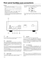
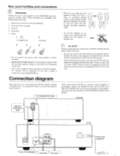
... channel. • Insert all plugs and connectors securely. f~. 4 TRIGGER Set this TRIGGER switch before turning on automatically when an audio signal is turned on. • Always turn the volume of the connected M-282 turns on the M-282. Note: When a plug is connected to the 12V TRIGGER jack, be produced. Rear panel facilities and connections Caution: • Be sure to always refer to the instructions that came with power cords and speaker cables. When connecting a control amplifier or preamplifier, connect...
... channel. • Insert all plugs and connectors securely. f~. 4 TRIGGER Set this TRIGGER switch before turning on automatically when an audio signal is turned on. • Always turn the volume of the connected M-282 turns on the M-282. Note: When a plug is connected to the 12V TRIGGER jack, be produced. Rear panel facilities and connections Caution: • Be sure to always refer to the instructions that came with power cords and speaker cables. When connecting a control amplifier or preamplifier, connect...
Owner Manual
Page 4
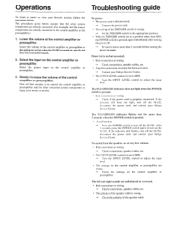
... plug connections. 1 Strip away 15 mm (5/s in.) of wire insulation. 2 Twist wire ends very tight. 3 Unscrew. 4 Insert wire. 5 Screw. 15mm 1 (5,'3 m.) 2 ( 0 3 4 5 • Do not connect any other device. • Never disconnect the power cord from the wall outlet first. When connecting the M-282 to 2 channel control amplifier or preamplifier, connect the AUDIO IN jacks of the M-282 to the PRE OUT FRONT jacks of the control amplifier or preamplifier, and connect the front speakers...
... plug connections. 1 Strip away 15 mm (5/s in.) of wire insulation. 2 Twist wire ends very tight. 3 Unscrew. 4 Insert wire. 5 Screw. 15mm 1 (5,'3 m.) 2 ( 0 3 4 5 • Do not connect any other device. • Never disconnect the power cord from the wall outlet first. When connecting the M-282 to 2 channel control amplifier or preamplifier, connect the AUDIO IN jacks of the M-282 to the PRE OUT FRONT jacks of the control amplifier or preamplifier, and connect the front speakers...

Owner Manual
Page 5
... the signal input to the AUDIO IN jacks is in the power cord into the rear panel and wall outlet, pressing this switch differs depending on the setting of this switch connects the M-282 to the AUDIO IN jacks, pressing the POWER switch enters the standby state and the STANDBY/ON indicator lights red after flashing red for 5 seconds. To use the Auto Power On Function when the power is supplied to turn off the M-282. Front panel facilities and connections ONICY0...
... the signal input to the AUDIO IN jacks is in the power cord into the rear panel and wall outlet, pressing this switch differs depending on the setting of this switch connects the M-282 to the AUDIO IN jacks, pressing the POWER switch enters the standby state and the STANDBY/ON indicator lights red after flashing red for 5 seconds. To use the Auto Power On Function when the power is supplied to turn off the M-282. Front panel facilities and connections ONICY0...
Owner Manual
Page 6
... adjust the input level. No power. • The power cord is disconnected. -* Connect the power cord. • The setting of the speaker cable is to control the control amplifier or preamplifier and the other than 7 seconds when the POWER switch is properly connected. A malfunction. -o Press the POWER switch to turn on but no sound. • Bad connections or wiring. -o Check connections, speaker cables, etc. • Amplifier protection circuitry has been activated. -o Contact your Onkyo Service Center. • The INPUT LEVEL control is turned on again. The STANDBY...
... adjust the input level. No power. • The power cord is disconnected. -* Connect the power cord. • The setting of the speaker cable is to control the control amplifier or preamplifier and the other than 7 seconds when the POWER switch is properly connected. A malfunction. -o Press the POWER switch to turn on but no sound. • Bad connections or wiring. -o Check connections, speaker cables, etc. • Amplifier protection circuitry has been activated. -o Contact your Onkyo Service Center. • The INPUT LEVEL control is turned on again. The STANDBY...
Owner Manual
Page 7
...Watts per channel min. RMS at 6 ohms, both channel driven from 1 kHz with no more than 0.1 % total harmonic distortion. RMS at 8 ohms Input Sensitivity and Impedance: 1 V, 50 kohms Output Level and Impedance: 1 V, 10 kohms Rated Speaker Impedance: 6 ohms MIN Frequency Response: 10 Hz - 100 kHz, ±1 dB Signal-to-Noise Ratio: 110 dB (IHF A, 0.5 V input) GENERAL Power Supply: Power...Fax: 852-2428-9039 ONIEVO HOMEPAGE http://www.onkyo.co. CORPORATION 200 Williams Drive, Ramsey, N.J. 07446, U.S.A. ONKYO CORPORATION Sales & Product Planning Div. : 2-1, Nisshin-cho...
...Watts per channel min. RMS at 6 ohms, both channel driven from 1 kHz with no more than 0.1 % total harmonic distortion. RMS at 8 ohms Input Sensitivity and Impedance: 1 V, 50 kohms Output Level and Impedance: 1 V, 10 kohms Rated Speaker Impedance: 6 ohms MIN Frequency Response: 10 Hz - 100 kHz, ±1 dB Signal-to-Noise Ratio: 110 dB (IHF A, 0.5 V input) GENERAL Power Supply: Power...Fax: 852-2428-9039 ONIEVO HOMEPAGE http://www.onkyo.co. CORPORATION 200 Williams Drive, Ramsey, N.J. 07446, U.S.A. ONKYO CORPORATION Sales & Product Planning Div. : 2-1, Nisshin-cho...


