
Owner Manual
Page 1
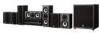
... Troubleshooting 101 En Following the instructions in your new Onkyo product. Please read this manual for purchasing this Onkyo product. 7.1ch THX Certified Digital Surround Receiver and Speaker Package HT-S9100THX AV Receiver (HT-R960) Front Speakers (SKF-960F) Center Speaker (SKC-960C) Surround Speakers (SKM-960S) Surround Back Speakers (SKB-960) Powered Subwoofer (SKW-960) Instruction Manual...
... Troubleshooting 101 En Following the instructions in your new Onkyo product. Please read this manual for purchasing this Onkyo product. 7.1ch THX Certified Digital Surround Receiver and Speaker Package HT-S9100THX AV Receiver (HT-R960) Front Speakers (SKF-960F) Center Speaker (SKC-960C) Surround Speakers (SKM-960S) Surround Back Speakers (SKB-960) Powered Subwoofer (SKW-960) Instruction Manual...
Owner Manual
Page 4
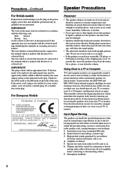
... power cord's plug is coloured brown must be performed only by connecting or discon- GROEBENZELL, GERMANY K. MIYAGI ONKYO EUROPE ELECTRONICS GmbH Placement • The speaker cabinets are made out of wood and are fed to them, even if the input power is marked with ... or coloured red. Amplifier oscillation. 5. If liquid is in compliance with an appropriate fuse. Microphone feedback. 4 Precautions-Continued Speaker Precautions For British models Replacement and mounting of an AC plug on its side or at surfaces that indicated on . 6. Note that ...
... power cord's plug is coloured brown must be performed only by connecting or discon- GROEBENZELL, GERMANY K. MIYAGI ONKYO EUROPE ELECTRONICS GmbH Placement • The speaker cabinets are made out of wood and are fed to them, even if the input power is marked with ... or coloured red. Amplifier oscillation. 5. If liquid is in compliance with an appropriate fuse. Microphone feedback. 4 Precautions-Continued Speaker Precautions For British models Replacement and mounting of an AC plug on its side or at surfaces that indicated on . 6. Note that ...
Owner Manual
Page 5
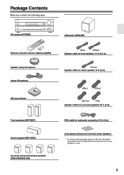
...: AV receiver (HT-R960) Subwoofer (SKW-960) Remote controller and two batteries (AA/R6) Speaker setup microphone Indoor FM antenna AM loop antenna (Red) (White) Speaker cable for front speakers 11 ft. (3.5 m) (Green) Speaker cable for center speaker 10 ft. (3 m) (Blue) (Gray) (Brown) (Tan) Speaker cables for surround speakers 30 ft. (9 m) Front speakers (SKF-960F) Center speaker (SKC-960C) Surround...
...: AV receiver (HT-R960) Subwoofer (SKW-960) Remote controller and two batteries (AA/R6) Speaker setup microphone Indoor FM antenna AM loop antenna (Red) (White) Speaker cable for front speakers 11 ft. (3.5 m) (Green) Speaker cable for center speaker 10 ft. (3 m) (Blue) (Gray) (Brown) (Tan) Speaker cables for surround speakers 30 ft. (9 m) Front speakers (SKF-960F) Center speaker (SKC-960C) Surround...

Owner Manual
Page 6
... 16 Installing the Batteries 17 Using the Remote Controller 17 Connecting the Speakers 18 Enjoying Home Theater 18 Speaker Sets A and B 19 Wall Mounting the Speakers 20 Speaker Connection Precautions 21 Connecting Speaker Set A 21 Connecting Speaker Set B (not included 21 Connecting Antennas 23 Connecting the Indoor FM... DAT Recorder 38 6 Connecting an RI Dock 39 Connecting Onkyo Components 40 Connecting the Power Cord 40 Turning On the AV Receiver 41 Turning On and Standby 41 First Time Setup 42 Automatic Speaker Setup 42 HDMI Input Setup 46 Component Video Input Setup ...
... 16 Installing the Batteries 17 Using the Remote Controller 17 Connecting the Speakers 18 Enjoying Home Theater 18 Speaker Sets A and B 19 Wall Mounting the Speakers 20 Speaker Connection Precautions 21 Connecting Speaker Set A 21 Connecting Speaker Set B (not included 21 Connecting Antennas 23 Connecting the Indoor FM... DAT Recorder 38 6 Connecting an RI Dock 39 Connecting Onkyo Components 40 Connecting the Power Cord 40 Turning On the AV Receiver 41 Turning On and Standby 41 First Time Setup 42 Automatic Speaker Setup 42 HDMI Input Setup 46 Component Video Input Setup ...
Owner Manual
Page 7
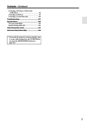
Contents-Continued Controlling a CD Player, CD Recorder, or MD Player 98 Controlling an RI Dock 99 Controlling a Cassette Recorder 100 Troubleshooting 101 Specifications 105 AV receiver HT-R960 105 Speaker Package HTP-960 106 Video Resolution Chart 107 Onscreen Setup Menu Map 108 * To reset the AV receiver to its factory defaults, turn it on and, while holding down the [VCR/DVR] button, press the [ON/STANDBY] button (see page 101). 7
Contents-Continued Controlling a CD Player, CD Recorder, or MD Player 98 Controlling an RI Dock 99 Controlling a Cassette Recorder 100 Troubleshooting 101 Specifications 105 AV receiver HT-R960 105 Speaker Package HTP-960 106 Video Resolution Chart 107 Onscreen Setup Menu Map 108 * To reset the AV receiver to its factory defaults, turn it on and, while holding down the [VCR/DVR] button, press the [ON/STANDBY] button (see page 101). 7
Owner Manual
Page 8
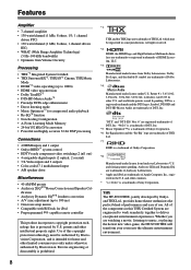
...Onkyo and THX Ltd., provides home theater enthusiasts the perfect blend of performance and ease of Apple Computer, Inc., registered in some jurisdictions. "96/24" is a trademark of DTS, Inc. *5 Music Optimizer™ is a trademark of Onkyo...; Color-coded 7.1 multichannel input • A/B speaker drive Miscellaneous • 40 AM/FM presets • Audyssey 2EQ®*8 Room Correction and Speaker Cal- All of THX Ltd. Reverse engineering or...pending. Use of this THX Certified System are trademarks of Sony Corporation. THX The HT-S9100THX, jointly developed by U.S. DTS is a ...
...Onkyo and THX Ltd., provides home theater enthusiasts the perfect blend of performance and ease of Apple Computer, Inc., registered in some jurisdictions. "96/24" is a trademark of DTS, Inc. *5 Music Optimizer™ is a trademark of Onkyo...; Color-coded 7.1 multichannel input • A/B speaker drive Miscellaneous • 40 AM/FM presets • Audyssey 2EQ®*8 Room Correction and Speaker Cal- All of THX Ltd. Reverse engineering or...pending. Use of this THX Certified System are trademarks of Sony Corporation. THX The HT-S9100THX, jointly developed by U.S. DTS is a ...
Owner Manual
Page 9
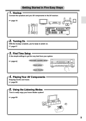
...the Listening Modes Time to get the very best from your home theater system! ☞ page 59 9 Getting Started in Five Easy Steps 1. First Time Setup A few simple settings to really enjoy your system. ☞ page 42 Automatic speaker setup Input setup Input display 4. Turning On With the ...VCR/DVR) OPTICAL 2 (CD) ASSIGNABLE IN 4 IN 3 (CBL/SAT) IN 2 HDMI ASSIGNABLE (VCR/DVR) IN 1 (DVD) COMPONENT VIDEO Y OUT SURR BACK SPEAKERS L AM SURR SPEAKERS CB/ PB CR/ PR IN 2 IN 1(DVD) OUT ASSIGNABLE IN OUT IN L CBL/SAT V VCR/DVR S DVD MONITOR OUT V S R ANTENNA FM 75...
...the Listening Modes Time to get the very best from your home theater system! ☞ page 59 9 Getting Started in Five Easy Steps 1. First Time Setup A few simple settings to really enjoy your system. ☞ page 42 Automatic speaker setup Input setup Input display 4. Turning On With the ...VCR/DVR) OPTICAL 2 (CD) ASSIGNABLE IN 4 IN 3 (CBL/SAT) IN 2 HDMI ASSIGNABLE (VCR/DVR) IN 1 (DVD) COMPONENT VIDEO Y OUT SURR BACK SPEAKERS L AM SURR SPEAKERS CB/ PB CR/ PR IN 2 IN 1(DVD) OUT ASSIGNABLE IN OUT IN L CBL/SAT V VCR/DVR S DVD MONITOR OUT V S R ANTENNA FM 75...
Owner Manual
Page 10
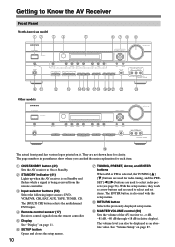
... DIMMER MEMORY TUNING MODE CLEAR SETUP MIC AUX INPUT VIDEO L AUDIO R AV RECEIVER HT-R960 JK Other models L M NOP QR STU V ON/STANDBY STANDBY TUNING PRESET ENTER W MASTER VOLUME THX PHONES MULTI CH A SPEAKERS B DVD TONE VCR/DVR CBL/SAT AUX TAPE TUNER CD SETUP RETURN MOVIE/TV ...MUSIC GAME LISTENING MODE DISPLAY DIGITAL INPUT RT/PTY/TP MEMORY TUNING MODE CLEAR SETUP MIC AUX INPUT VIDEO L AUDIO R AV RECEIVER HT-R960 S The actual front panel ...
... DIMMER MEMORY TUNING MODE CLEAR SETUP MIC AUX INPUT VIDEO L AUDIO R AV RECEIVER HT-R960 JK Other models L M NOP QR STU V ON/STANDBY STANDBY TUNING PRESET ENTER W MASTER VOLUME THX PHONES MULTI CH A SPEAKERS B DVD TONE VCR/DVR CBL/SAT AUX TAPE TUNER CD SETUP RETURN MOVIE/TV ...MUSIC GAME LISTENING MODE DISPLAY DIGITAL INPUT RT/PTY/TP MEMORY TUNING MODE CLEAR SETUP MIC AUX INPUT VIDEO L AUDIO R AV RECEIVER HT-R960 S The actual front panel ...
Owner Manual
Page 11
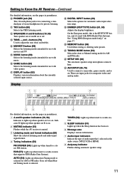
...(59) Selects the listening modes intended for private listening. Display 12 3 4 56 7 For detailed information, see the pages in parentheses. 1 A and B speaker indicators (19, 50) Indicator A lights up when tuned to connect a camcorder, game console, and so on page 57. N MOVIE/TV button (59)...listening modes intended for connecting a standard pair of audio input that supports RDS (Radio Data System). R DIGITAL INPUT button (49) Selects the options for AM and FM radio. Indicator B lights up when speaker set A is on . 2 MUTING indicator (51) Flashes while the AV receiver is ...
...(59) Selects the listening modes intended for private listening. Display 12 3 4 56 7 For detailed information, see the pages in parentheses. 1 A and B speaker indicators (19, 50) Indicator A lights up when tuned to connect a camcorder, game console, and so on page 57. N MOVIE/TV button (59)...listening modes intended for connecting a standard pair of audio input that supports RDS (Radio Data System). R DIGITAL INPUT button (49) Selects the options for AM and FM radio. Indicator B lights up when speaker set A is on . 2 MUTING indicator (51) Flashes while the AV receiver is ...

Owner Manual
Page 12
...CBL/SAT) 1 (VCR/DVR) OPTICAL 2 (CD) ASSIGNABLE IN 4 IN 3 (CBL/SAT) IN 2 HDMI ASSIGNABLE (VCR/DVR) IN 1 (DVD) COMPONENT VIDEO Y OUT SURR BACK SPEAKERS L AM SURR SPEAKERS CB/ PB CR/ PR IN 2(CBL/SAT) IN 1(DVD) OUT ASSIGNABLE IN OUT IN L CBL/SAT V VCR/DVR S IN OUT IN IN OUT IN...and output, such as a DVD player, DVD recorder, or DVR (digital video recorder). See "HDMI Input Setup" on another -capable Onkyo component for remote and system control. nected to suit your setup. They're assignable, which means you can assign each one to an input selector to the jack...
...CBL/SAT) 1 (VCR/DVR) OPTICAL 2 (CD) ASSIGNABLE IN 4 IN 3 (CBL/SAT) IN 2 HDMI ASSIGNABLE (VCR/DVR) IN 1 (DVD) COMPONENT VIDEO Y OUT SURR BACK SPEAKERS L AM SURR SPEAKERS CB/ PB CR/ PR IN 2(CBL/SAT) IN 1(DVD) OUT ASSIGNABLE IN OUT IN L CBL/SAT V VCR/DVR S IN OUT IN IN OUT IN...and output, such as a DVD player, DVD recorder, or DVR (digital video recorder). See "HDMI Input Setup" on another -capable Onkyo component for remote and system control. nected to suit your setup. They're assignable, which means you can assign each one to an input selector to the jack...
Owner Manual
Page 13
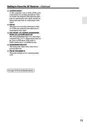
... B. O DVD FRONT L/R, CENTER, SUBWOOFER, SURR L/R, and SURR BACK L/R This analog multichannel input is for connecting the video signal. Q FRONT SPEAKERS B These push terminals are S-Video and composite video input jacks for connecting a DVD player. N DVD IN This input is for connecting a component with a 5.1/7.1-channel analog ...
... B. O DVD FRONT L/R, CENTER, SUBWOOFER, SURR L/R, and SURR BACK L/R This analog multichannel input is for connecting the video signal. Q FRONT SPEAKERS B These push terminals are S-Video and composite video input jacks for connecting a DVD player. N DVD IN This input is for connecting a component with a 5.1/7.1-channel analog ...

Owner Manual
Page 14
... grille, push the fasteners at the corners into the grille plug holes on the speaker cabinet. The supplied speaker cables are for connecting the speakers to remove the bottom of the speaker grille with the supplied speaker cables. In the same way, gently pull the upper edge of the SKC-960C... toward you to remove it gently toward you to the AV receiver with both hands, pull it from the speaker cabinet. 3. Speaker Package Front, Center, Surround, and Surround Back Speakers (SKF-960F, SKC-960C, SKM-960S, SKB-960) ■ Rear SKF-960F 1 Using the Cork Spacers for a More ...
... grille, push the fasteners at the corners into the grille plug holes on the speaker cabinet. The supplied speaker cables are for connecting the speakers to remove the bottom of the speaker grille with the supplied speaker cables. In the same way, gently pull the upper edge of the SKC-960C... toward you to remove it gently toward you to the AV receiver with both hands, pull it from the speaker cabinet. 3. Speaker Package Front, Center, Surround, and Surround Back Speakers (SKF-960F, SKC-960C, SKM-960S, SKB-960) ■ Rear SKF-960F 1 Using the Cork Spacers for a More ...
Owner Manual
Page 16
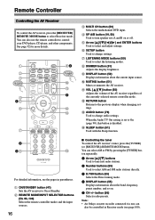
...Standby. A ON/STANDBY button (41) Sets the AV receiver to change audio settings. D SP A/B button (19, 50) Used to turn speaker sets A and B on . 5 CH +/- G LISTENING MODE buttons (59) Used to select Receiver mode. Remote Controller Controlling the AV Receiver To control...DISPLAY button (55) Displays information about the current input source. E Arrow and ENTER buttons Used to change settings. Note: • An Onkyo cassette recorder connected via can also be controlled in parentheses. L RETURN button Returns to On (page 90), this button is disabled. H DIMMER...
...Standby. A ON/STANDBY button (41) Sets the AV receiver to change audio settings. D SP A/B button (19, 50) Used to turn speaker sets A and B on . 5 CH +/- G LISTENING MODE buttons (59) Used to select Receiver mode. Remote Controller Controlling the AV Receiver To control...DISPLAY button (55) Displays information about the current input source. E Arrow and ENTER buttons Used to change settings. Note: • An Onkyo cassette recorder connected via can also be controlled in parentheses. L RETURN button Returns to On (page 90), this button is disabled. H DIMMER...
Owner Manual
Page 18
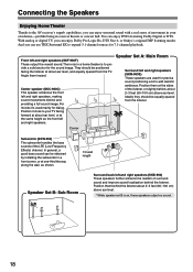
... EX to expand 5.1-channel sources for 7.1-channel playback. Their role in a home theater is on, these speakers output no sound. 18 Speaker Set A: Main Room Surround left and right speakers (SKM-960S) These speakers are used mainly for the sound image. Position them behind the listener about ...2-3 feet (60-100 cm) above ear level. And you can enjoy Dolby Pro Logic IIx, DTS Neo:6, or Onkyo...
... EX to expand 5.1-channel sources for 7.1-channel playback. Their role in a home theater is on, these speakers output no sound. 18 Speaker Set A: Main Room Surround left and right speakers (SKM-960S) These speakers are used mainly for the sound image. Position them behind the listener about ...2-3 feet (60-100 cm) above ear level. And you can enjoy Dolby Pro Logic IIx, DTS Neo:6, or Onkyo...
Owner Manual
Page 19
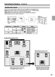
... HT-R960 Speaker set A On Off Speaker set B On Off On Off Indicator AB A B Output Set A: 5.1 channels Set B: 2 channels Set A: 7.1 channels Set B: 2 channels No sound ■ Main Room (speaker set A) Front left speaker Subwoofer Center speaker Front right speaker Surround left speaker Surround back left speaker Surround back right speaker Surround right speaker ■ Sub Room (speaker set B) * While speaker set B is on , speaker...
... HT-R960 Speaker set A On Off Speaker set B On Off On Off Indicator AB A B Output Set A: 5.1 channels Set B: 2 channels Set A: 7.1 channels Set B: 2 channels No sound ■ Main Room (speaker set A) Front left speaker Subwoofer Center speaker Front right speaker Surround left speaker Surround back left speaker Surround back right speaker Surround right speaker ■ Sub Room (speaker set B) * While speaker set B is on , speaker...
Owner Manual
Page 20
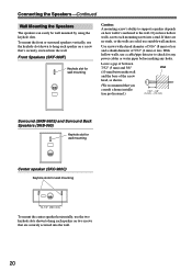
...pipe detector to check for wall mounting 10-1/4" (260 mm) To mount the center speaker horizontally, use the keyhole slot shown to hang each speaker on a screw that you have hollow walls, screw each speaker on how well it's anchored to hang each mounting screw into the wall. To...and the base of 5/32" (4 mm) or less. If you consult a home installation professional.) 7/32" - 3/8" (5 mm) - (10 mm) Surround (SKM-960S) and Surround Back Speakers (SKB-960) Keyhole slot for wall mounting Center speaker (SKC-960C) Keyhole slots for any power cables or water pipes before making any...
...pipe detector to check for wall mounting 10-1/4" (260 mm) To mount the center speaker horizontally, use the keyhole slot shown to hang each speaker on a screw that you have hollow walls, screw each speaker on how well it's anchored to hang each mounting screw into the wall. To...and the base of 5/32" (4 mm) or less. If you consult a home installation professional.) 7/32" - 3/8" (5 mm) - (10 mm) Surround (SKM-960S) and Surround Back Speakers (SKB-960) Keyhole slot for wall mounting Center speaker (SKC-960C) Keyhole slots for any power cables or water pipes before making any...
Owner Manual
Page 21
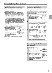
... circuit may damage the AV receiver. • Don't connect more than one speaker to only negative (-) terminals. Connecting Speaker Set A The AV receiver's positive (+) speaker terminals and the speaker's positive (+) terminals are color-coded for a long period of phase and will...(+) terminals to only positive (+) terminals, and negative (-) terminals to several terminals. Connecting the Speakers-Continued Speaker Connection Precautions Read the following before connecting any speakers: • Disconnect the power cord from the wall outlet before making sure that the terminals are...
... circuit may damage the AV receiver. • Don't connect more than one speaker to only negative (-) terminals. Connecting Speaker Set A The AV receiver's positive (+) speaker terminals and the speaker's positive (+) terminals are color-coded for a long period of phase and will...(+) terminals to only positive (+) terminals, and negative (-) terminals to several terminals. Connecting the Speakers-Continued Speaker Connection Precautions Read the following before connecting any speakers: • Disconnect the power cord from the wall outlet before making sure that the terminals are...
Owner Manual
Page 22
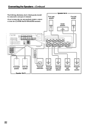
... SURR BACK L PRE OUT L SUB WOOFER FRONT SPEAKERS A L CENTER SPEAKER R TAPE R CBL/SAT VCR/DVR R SUB WOOFER DVD R FRONT SPEAKERS B SURR BACK SPEAKERS L SURR SPEAKERS FRONT SPEAKERS A L R R CENTER SPEAKER Front right Front left speaker speaker Speaker Set B Powered subwoofer Surround back right speaker Surround back left speaker Surround right speaker Surround left (L) SURR BACK SPEAKERS terminals. Connecting the Speakers-Continued The following illustration shows which...
... SURR BACK L PRE OUT L SUB WOOFER FRONT SPEAKERS A L CENTER SPEAKER R TAPE R CBL/SAT VCR/DVR R SUB WOOFER DVD R FRONT SPEAKERS B SURR BACK SPEAKERS L SURR SPEAKERS FRONT SPEAKERS A L R R CENTER SPEAKER Front right Front left speaker speaker Speaker Set B Powered subwoofer Surround back right speaker Surround back left speaker Surround right speaker Surround left (L) SURR BACK SPEAKERS terminals. Connecting the Speakers-Continued The following illustration shows which...
Owner Manual
Page 23
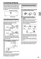
... indoor AM loop antenna, try a commercially available outdoor FM antenna instead (see page 24). Push Insert wire Release AM ANTENNA Once your AV receiver, TV, speaker cables, and power cords. Once your AV receiver is ready for use only. 1 Attach the FM antenna, as possible from your AV receiver is ready...
... indoor AM loop antenna, try a commercially available outdoor FM antenna instead (see page 24). Push Insert wire Release AM ANTENNA Once your AV receiver, TV, speaker cables, and power cords. Once your AV receiver is ready for use only. 1 Attach the FM antenna, as possible from your AV receiver is ready...
Owner Manual
Page 25
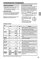
... audio. Several standard analog audio cables can cause noise or malfunctions). • To prevent interference, keep audio and video cables away from power cords and speaker cables. And use yellow plugs to OPTICAL enjoy Dolby Digital and DTS. The audio quality is the same as for analog audio and R can carry...
... audio. Several standard analog audio cables can cause noise or malfunctions). • To prevent interference, keep audio and video cables away from power cords and speaker cables. And use yellow plugs to OPTICAL enjoy Dolby Digital and DTS. The audio quality is the same as for analog audio and R can carry...


