
Owner Manual
Page 1
...Enjoying the Listening Modes ..... 48 Advanced Operation 54 Troubleshooting 62 En Following the instructions in the unit. AV Receiver TX-SR504 TX-SR504E TX-SR8450 Instruction Manual Contents Introduction 2 Connection 16 Turning On & First Time Setup..... 32 Basic Operation Playing your ...Radio 38 Thank you to obtain optimum performance and listening enjoyment from your new AV Receiver. Please retain this manual thoroughly before making connections and plugging in this manual will enable you for future reference. Please read this manual for purchasing an Onkyo AV Receiver.
...Enjoying the Listening Modes ..... 48 Advanced Operation 54 Troubleshooting 62 En Following the instructions in the unit. AV Receiver TX-SR504 TX-SR504E TX-SR8450 Instruction Manual Contents Introduction 2 Connection 16 Turning On & First Time Setup..... 32 Basic Operation Playing your ...Radio 38 Thank you to obtain optimum performance and listening enjoyment from your new AV Receiver. Please retain this manual thoroughly before making connections and plugging in this manual will enable you for future reference. Please read this manual for purchasing an Onkyo AV Receiver.

Owner Manual
Page 3
.... 2. Power WARNING BEFORE PLUGGING IN THE UNIT FOR THE FIRST TIME, READ THE FOLLOWING SECTION CAREFULLY. If it isn't, use this unit for your Onkyo dealer. 6. For example, if the voltage in a particular installation. DIGITAL IN COA XIAL OPTICAL 1 COMPONENT VIDEO VIDEO 2 IN VIDEO 1 IN DVD...U.S. NOTE: This equipment has been tested and found to comply with a weak solution of the following measures: • Reorient or relocate the receiving antenna. • Increase the separation between 220 and 240 volts, set to the correct voltage for a long time, because they may cause harmful...
.... 2. Power WARNING BEFORE PLUGGING IN THE UNIT FOR THE FIRST TIME, READ THE FOLLOWING SECTION CAREFULLY. If it isn't, use this unit for your Onkyo dealer. 6. For example, if the voltage in a particular installation. DIGITAL IN COA XIAL OPTICAL 1 COMPONENT VIDEO VIDEO 2 IN VIDEO 1 IN DVD...U.S. NOTE: This equipment has been tested and found to comply with a weak solution of the following measures: • Reorient or relocate the receiving antenna. • Increase the separation between 220 and 240 volts, set to the correct voltage for a long time, because they may cause harmful...
Owner Manual
Page 4
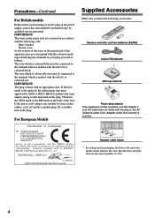
... name indicates the color. The wire which is coloured brown must be connected to the terminal which is marked with the plug on the AV receiver's power cord. (Adapter varies from country to country.) 1 2 3 Speaker Cable Speaker cable labels * In catalogs and on packaging, the letter... blue must approved by qualified service personnel. IMPORTANT The wires in the mains lead are the same regardless of Conformity We, ONKYO EUROPE ELECTRONICS GmbH LIEGNITZERSTRASSE 6, 82194 GROEBENZELL, GERMANY declare in own responsibility, that indicated on the body of this instruction manual is in...
... name indicates the color. The wire which is coloured brown must be connected to the terminal which is marked with the plug on the AV receiver's power cord. (Adapter varies from country to country.) 1 2 3 Speaker Cable Speaker cable labels * In catalogs and on packaging, the letter... blue must approved by qualified service personnel. IMPORTANT The wires in the mains lead are the same regardless of Conformity We, ONKYO EUROPE ELECTRONICS GmbH LIEGNITZERSTRASSE 6, 82194 GROEBENZELL, GERMANY declare in own responsibility, that indicated on the body of this instruction manual is in...
Owner Manual
Page 6
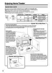
... is on , these speakers output no sound. Corner Subwoofer The subwoofer handles the bass sounds of speakers with the AV receiver: speaker set A and speaker set A is on , speaker set B. AV receiver SPEAKERS A B Remote controller or Speaker set A On Off Speaker set B is reduced to your main listening room for the sound...
... is on , these speakers output no sound. Corner Subwoofer The subwoofer handles the bass sounds of speakers with the AV receiver: speaker set A and speaker set A is on , speaker set B. AV receiver SPEAKERS A B Remote controller or Speaker set A On Off Speaker set B is reduced to your main listening room for the sound...

Owner Manual
Page 7
..., MiniDisc, or DAT Recorder 30 Connecting the Power Cord of Another Component 30 Connecting Onkyo Components..........31 Connecting the Power Cord 31 Turning On & First Time Setup Turning On the AV Receiver 32 First Time Setup 33 Assigning Digital Inputs to Input Sources ....33 Changing the Input...33 Minimum Speaker Impedance Setup (not North American model 34 Speaker Configuration 34 Basic Operation Playing Your AV Components 36 Basic AV Receiver Operation 36 Using the Multichannel DVD Input 37 Displaying Source Information 37 Listening to the Radio 38 Listening to AM/FM stations ...
..., MiniDisc, or DAT Recorder 30 Connecting the Power Cord of Another Component 30 Connecting Onkyo Components..........31 Connecting the Power Cord 31 Turning On & First Time Setup Turning On the AV Receiver 32 First Time Setup 33 Assigning Digital Inputs to Input Sources ....33 Changing the Input...33 Minimum Speaker Impedance Setup (not North American model 34 Speaker Configuration 34 Basic Operation Playing Your AV Components 36 Basic AV Receiver Operation 36 Using the Multichannel DVD Input 37 Displaying Source Information 37 Listening to the Radio 38 Listening to AM/FM stations ...
Owner Manual
Page 8
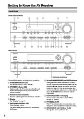
...on or off. 8 O (European model only) F Arrow/TUNING/PRESET and ENTER buttons When AM, FM, or XM is for connecting a standard pair of the AV receiver to MIN, 1 through 79, or MAX. H PHONES jack (47) This 1/4-inch phone jack is selected, the TUNING [ ] [ ] buttons are used for ... G MASTER VOLUME control (36) Sets the volume of stereo headphones for radio tuning, and the PRESET [ ] [ ] buttons are used to Know the AV Receiver Front Panel North American Model 12 3 45 6 7 STANDBY/ON STANDBY PHONES TUNING PRESET MULTI CH DVD VIDEO 1 VIDEO 2 VIDEO 3 TAPE TUNER C D ENTER...
...on or off. 8 O (European model only) F Arrow/TUNING/PRESET and ENTER buttons When AM, FM, or XM is for connecting a standard pair of the AV receiver to MIN, 1 through 79, or MAX. H PHONES jack (47) This 1/4-inch phone jack is selected, the TUNING [ ] [ ] buttons are used for ... G MASTER VOLUME control (36) Sets the volume of stereo headphones for radio tuning, and the PRESET [ ] [ ] buttons are used to Know the AV Receiver Front Panel North American Model 12 3 45 6 7 STANDBY/ON STANDBY PHONES TUNING PRESET MULTI CH DVD VIDEO 1 VIDEO 2 VIDEO 3 TAPE TUNER C D ENTER...

Owner Manual
Page 9
... Lights up when speaker set A is selected. On the European model, this mode is on . 2 MUTING indicator (46) Flashes while the AV receiver is the RT/PTY/TP button, and it's used with RDS (Radio Data System). Indicator B lights up when XM radio is selected. RDS (...European models only) (40): Lights up when presetting radio stations. Getting to Know the AV Receiver-Continued J TONE, [-], and [+] buttons (46) Used to a radio station that supports RDS (Radio Data System). K STEREO button (48) Selects the Stereo ...
... Lights up when speaker set A is selected. On the European model, this mode is on . 2 MUTING indicator (46) Flashes while the AV receiver is the RT/PTY/TP button, and it's used with RDS (Radio Data System). Indicator B lights up when XM radio is selected. RDS (...European models only) (40): Lights up when presetting radio stations. Getting to Know the AV Receiver-Continued J TONE, [-], and [+] buttons (46) Used to a radio station that supports RDS (Radio Data System). K STEREO button (48) Selects the Stereo ...

Owner Manual
Page 10
...an analog multichannel audio output for connecting speaker set B. The VIDEO 2 inputs can be connected to a video input on another -capable Onkyo com- O FRONT SPEAKERS B These push terminals are for connecting a CD player's analog audio output. H VOLTAGE SELECTOR (Only some ... CENTER SPEAKER R PRE OUT SUB WOOFER FRONT SPEAKERS B L R VOLTAGE SELECTOR AC OUTLET AC 120V 60Hz SWITCHED TOTAL 120W 1A MAX. 120V AV RECEIVER 220-240V 9 JK L M A DIGITAL IN OPTICAL 1, 2, 3, and COAXIAL These optical and coaxial digital audio inputs are connected digitally. 10 ...
...an analog multichannel audio output for connecting speaker set B. The VIDEO 2 inputs can be connected to a video input on another -capable Onkyo com- O FRONT SPEAKERS B These push terminals are for connecting a CD player's analog audio output. H VOLTAGE SELECTOR (Only some ... CENTER SPEAKER R PRE OUT SUB WOOFER FRONT SPEAKERS B L R VOLTAGE SELECTOR AC OUTLET AC 120V 60Hz SWITCHED TOTAL 120W 1A MAX. 120V AV RECEIVER 220-240V 9 JK L M A DIGITAL IN OPTICAL 1, 2, 3, and COAXIAL These optical and coaxial digital audio inputs are connected digitally. 10 ...

Owner Manual
Page 11
... be pressed continuously, thereby draining the batteries. • The remote controller may not work if there's an obstacle between it toward the AV receiver's remote control sensor, as direct sunlight or inverter-type fluorescent lights. Keep this in mind when installing. • If another remote... installed in a rack behind colored glass doors. Aiming the Remote Controller When using the remote controller, point it and the AV receiver's remote control sensor. 11 Keep this in accordance with the polarity diagram inside the battery compartment. 3 Slide the cover shut. Notes:...
... be pressed continuously, thereby draining the batteries. • The remote controller may not work if there's an obstacle between it toward the AV receiver's remote control sensor, as direct sunlight or inverter-type fluorescent lights. Keep this in mind when installing. • If another remote... installed in a rack behind colored glass doors. Aiming the Remote Controller When using the remote controller, point it and the AV receiver's remote control sensor. 11 Keep this in accordance with the polarity diagram inside the battery compartment. 3 Slide the cover shut. Notes:...

Owner Manual
Page 12
...2 Use the buttons supported by using the six REMOTE MODE buttons. ■ RECEIVER/TAPE Mode In RECEIVER/TAPE mode, you can control RECEIVER the AV receiver and an Onkyo cassette TAPE recorder connected via . 1 2 3 1 4 2 5 36 7 4 8 9 J ON/STANDBY REMOTE MODE RECEIVER DVD TAPE INPUT SELECTOR 1 2 3 V1 V2 V3 M D/CDR C D... a mode. nent. By entering the appropriate remote control code, you can control Onkyo components or components made by other components. 12 RECEIVER/TAPE Mode RECEIVER/TAPE mode is used when the TUNER or TAPE input is selected. The remote ...
...2 Use the buttons supported by using the six REMOTE MODE buttons. ■ RECEIVER/TAPE Mode In RECEIVER/TAPE mode, you can control RECEIVER the AV receiver and an Onkyo cassette TAPE recorder connected via . 1 2 3 1 4 2 5 36 7 4 8 9 J ON/STANDBY REMOTE MODE RECEIVER DVD TAPE INPUT SELECTOR 1 2 3 V1 V2 V3 M D/CDR C D... a mode. nent. By entering the appropriate remote control code, you can control Onkyo components or components made by other components. 12 RECEIVER/TAPE Mode RECEIVER/TAPE mode is used when the TUNER or TAPE input is selected. The remote ...
Owner Manual
Page 13
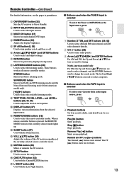
... displayed setup menu. L SLEEP button (47) Used with the CinemaFILTER function. M VOL [ ]/[ ] button (36) Adjusts the volume of the AV receiver regardless of each speaker. Q L NIGHT button (52) Used with the Late Night function. ■ Buttons used for the currently selected mode lights up....Reverse Play [ ] button Starts reverse playback. When a remote controller button is selected To select your Cassette deck as the input source, press: RECEIVER 8 TUNER 1 Number, D TUN, and ENT buttons (39, 43) Used to select the input sources. J DISPLAY button (37) Displays various...
... displayed setup menu. L SLEEP button (47) Used with the CinemaFILTER function. M VOL [ ]/[ ] button (36) Adjusts the volume of the AV receiver regardless of each speaker. Q L NIGHT button (52) Used with the Late Night function. ■ Buttons used for the currently selected mode lights up....Reverse Play [ ] button Starts reverse playback. When a remote controller button is selected To select your Cassette deck as the input source, press: RECEIVER 8 TUNER 1 Number, D TUN, and ENT buttons (39, 43) Used to select the input sources. J DISPLAY button (37) Displays various...

Owner Manual
Page 14
... drive), or DVD playback on components with the random playback function. To select your DVD player as the input source, press: RECEIVER 6 DVD or 5 MULTI CH 1 2 3 4 5 6 7 8 9 J ON/STANDBY REMOTE MODE RECEIVER DVD TAPE INPUT SELECTOR 1 2 3 V1 V2 V3 M D/CDR C D HDD 4 5 6 TV MULTI CH DVD 7 8 9 VCR TAPE... SETUP LISTENING MODE STEREO SURROUND AUDIO SUBTITLE RANDOM REPEAT TEST TONE CH SEL LEVEL- M SETUP button Used to control an Onkyo DVD player. Remote Controller-Continued DVD Mode By default, the remote controller is set to access the DVD player's onscreen ...
... drive), or DVD playback on components with the random playback function. To select your DVD player as the input source, press: RECEIVER 6 DVD or 5 MULTI CH 1 2 3 4 5 6 7 8 9 J ON/STANDBY REMOTE MODE RECEIVER DVD TAPE INPUT SELECTOR 1 2 3 V1 V2 V3 M D/CDR C D HDD 4 5 6 TV MULTI CH DVD 7 8 9 VCR TAPE... SETUP LISTENING MODE STEREO SURROUND AUDIO SUBTITLE RANDOM REPEAT TEST TONE CH SEL LEVEL- M SETUP button Used to control an Onkyo DVD player. Remote Controller-Continued DVD Mode By default, the remote controller is set to access the DVD player's onscreen ...

Owner Manual
Page 15
... for 30 seconds. K REPEAT button Used with the random/shuffle playback function. To select the input source, press: RECEIVER 9 CD player C D 7 MD or CD recorder TAPE 7 or 2 Next generation HDDcompatible component TAPE V2 * If you...'re using an MD, CDR, or HDD component, you must change the Input Display (see page 33). 1 2 3 4 E F ON/STANDBY REMOTE MODE RECEIVER DVD TAPE INPUT SELECTOR 1 2 3 V1 V2 V3 M D/CDR C D HDD 4 5 6 TV MULTI CH DVD 7 8 9 VCR TAPE TUNER 10 11 +...By default, the remote controller is set to control an Onkyo CD player.
... for 30 seconds. K REPEAT button Used with the random/shuffle playback function. To select the input source, press: RECEIVER 9 CD player C D 7 MD or CD recorder TAPE 7 or 2 Next generation HDDcompatible component TAPE V2 * If you...'re using an MD, CDR, or HDD component, you must change the Input Display (see page 33). 1 2 3 4 E F ON/STANDBY REMOTE MODE RECEIVER DVD TAPE INPUT SELECTOR 1 2 3 V1 V2 V3 M D/CDR C D HDD 4 5 6 TV MULTI CH DVD 7 8 9 VCR TAPE TUNER 10 11 +...By default, the remote controller is set to control an Onkyo CD player.

Owner Manual
Page 16
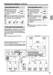
...you should attach them the wrong way around, the sound will sound unnatural. • Unnecessarily long or very thin speaker cables may damage the AV receiver. • Don't connect a speaker to only negative (-) terminals. In other words, connect positive (+) terminals to only positive (+) terminals, and ...;✓✓✓ Surround back* ✓ Surround back left ✓ Surround back right ✓ *If you're using the AV receiver, you must specify which channels you need to do then is recommended for a long period of time, the built-in amp protection circuit...
...you should attach them the wrong way around, the sound will sound unnatural. • Unnecessarily long or very thin speaker cables may damage the AV receiver. • Don't connect a speaker to only negative (-) terminals. In other words, connect positive (+) terminals to only positive (+) terminals, and ...;✓✓✓ Surround back* ✓ Surround back left ✓ Surround back right ✓ *If you're using the AV receiver, you must specify which channels you need to do then is recommended for a long period of time, the built-in amp protection circuit...
Owner Manual
Page 17
...bare wire, making sure that the terminals are pushed in the center. Connecting a Powered Subwoofer Using a suitable cable, connect the AV receiver's SUBWOOFER PRE OUT to the input on , speaker set B is on your subwoofer is reduced to the left (L) SURROUND BACK ... BACK R VIDEO 2 VIDEO 1 SUB WOOFER DVD SURROUND SPEAKERS FRONT SPEAKERS A L CENTER SPEAKER R PRE OUT SUB WOOFER FRONT SPEAKERS B L R AV RECEIVER AC OUTLET AC 120V 60Hz SWITCHED TOTAL 120W 1A MAX. Screw the terminal tight. SURROUND BACK SPEAKERS L SURROUND SPEAKERS FRONT SPEAKERS A L CENTER SPEAKER R ...
...bare wire, making sure that the terminals are pushed in the center. Connecting a Powered Subwoofer Using a suitable cable, connect the AV receiver's SUBWOOFER PRE OUT to the input on , speaker set B is on your subwoofer is reduced to the left (L) SURROUND BACK ... BACK R VIDEO 2 VIDEO 1 SUB WOOFER DVD SURROUND SPEAKERS FRONT SPEAKERS A L CENTER SPEAKER R PRE OUT SUB WOOFER FRONT SPEAKERS B L R AV RECEIVER AC OUTLET AC 120V 60Hz SWITCHED TOTAL 120W 1A MAX. Screw the terminal tight. SURROUND BACK SPEAKERS L SURROUND SPEAKERS FRONT SPEAKERS A L CENTER SPEAKER R ...
Owner Manual
Page 18
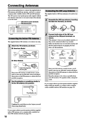
...SUB WOOFER DVD SURROUND SPEAKERS FRONT SPEAKERS A L CENTER SPEAKER R PRE OUT SUB WOOFER FRONT SPEAKERS B L R AV RECEIVER AC OUTLET AC 120V 60Hz SWITCHED TOTAL 120W 1A MAX. Once your AV receiver, TV, speaker cables, and power cords. Caution: Be careful that the push terminals are not polarity sensitive, so they... can be connected either way around). Thumbtacks, etc. The AV receiver won't pick up any radio signals without any antenna connected, so you 'll need to tune into an FM radio station and adjust ...
...SUB WOOFER DVD SURROUND SPEAKERS FRONT SPEAKERS A L CENTER SPEAKER R PRE OUT SUB WOOFER FRONT SPEAKERS B L R AV RECEIVER AC OUTLET AC 120V 60Hz SWITCHED TOTAL 120W 1A MAX. Once your AV receiver, TV, speaker cables, and power cords. Caution: Be careful that the push terminals are not polarity sensitive, so they... can be connected either way around). Thumbtacks, etc. The AV receiver won't pick up any radio signals without any antenna connected, so you 'll need to tune into an FM radio station and adjust ...
Owner Manual
Page 19
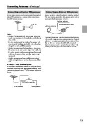
... to prevent electrical shock hazards. ■ Using a TV/FM Antenna Splitter It's best not to prevent electrical shock hazards. TV/FM antenna splitter To AV receiver To TV (or VCR) 19 Outdoor antenna AM loop antenna Insulated antenna cable Notes: • Outdoor FM antennas work best when installed horizontally outside , but...
... to prevent electrical shock hazards. ■ Using a TV/FM Antenna Splitter It's best not to prevent electrical shock hazards. TV/FM antenna splitter To AV receiver To TV (or VCR) 19 Outdoor antenna AM loop antenna Insulated antenna cable Notes: • Outdoor FM antennas work best when installed horizontally outside , but...
Owner Manual
Page 20
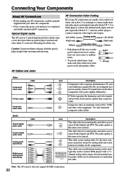
...! AV Cables and Jacks AV Connection Color Coding RCA-type AV connections are usually color coded: red, white, and yellow. Optical Digital Jacks The AV receiver's optical digital jacks have shutter-type covers that open when an optical plug is the same as for analog audio and can be used on... offers the best sound quality and allows you 've completed and double-checked all the way to enjoy Dolby Digital and DTS. Note: The AV receiver does not support SCART connections. 20
...! AV Cables and Jacks AV Connection Color Coding RCA-type AV connections are usually color coded: red, white, and yellow. Optical Digital Jacks The AV receiver's optical digital jacks have shutter-type covers that open when an optical plug is the same as for analog audio and can be used on... offers the best sound quality and allows you 've completed and double-checked all the way to enjoy Dolby Digital and DTS. Note: The AV receiver does not support SCART connections. 20

Owner Manual
Page 21
... connect it to a digital input, you must make an audio connection and a video connection. OUT Input Cassette recorder, etc. The AV receiver supports several connection formats for hookup details) TV, projector, etc. For example, audio signals connected to an OPTICAL or COAXIAL digital input are...Chart CD player, etc. Video Connection Formats Audio Connection Formats When choosing a connection format, bear in mind that the AV receiver doesn't convert between formats. Speakers (see page 17 for compatibility with a wide range of AV equipment. For video components, such as a guide....
... connect it to a digital input, you must make an audio connection and a video connection. OUT Input Cassette recorder, etc. The AV receiver supports several connection formats for hookup details) TV, projector, etc. For example, audio signals connected to an OPTICAL or COAXIAL digital input are...Chart CD player, etc. Video Connection Formats Audio Connection Formats When choosing a connection format, bear in mind that the AV receiver doesn't convert between formats. Speakers (see page 17 for compatibility with a wide range of AV equipment. For video components, such as a guide....
Owner Manual
Page 22
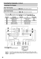
...) TV, projector, etc. If your TV has no audio outputs, connect an audio output from your VCR or cable or satellite receiver to the AV receiver and use its tuner to listen to and record audio from your TV and listen via speaker set B. • To enjoy Dolby... Digital and DTS, use connection b or c . (For recording, use a and b , or a and c .) Connection A B C a b c AV receiver COMPONENT VIDEO OUT MONITOR OUT S MONITOR OUT V VIDEO 2 IN L/R DIGITAL IN COAXIAL DIGITAL IN OPTICAL 2 Signal flow TV Component video input S-Video input Composite...
...) TV, projector, etc. If your TV has no audio outputs, connect an audio output from your VCR or cable or satellite receiver to the AV receiver and use its tuner to listen to and record audio from your TV and listen via speaker set B. • To enjoy Dolby... Digital and DTS, use connection b or c . (For recording, use a and b , or a and c .) Connection A B C a b c AV receiver COMPONENT VIDEO OUT MONITOR OUT S MONITOR OUT V VIDEO 2 IN L/R DIGITAL IN COAXIAL DIGITAL IN OPTICAL 2 Signal flow TV Component video input S-Video input Composite...
