
Owner Manual
Page 1
... Radio 38 Thank you for future reference. Following the instructions in the unit. Please read this manual thoroughly before making connections and plugging in this manual for purchasing an Onkyo AV Receiver. AV Receiver TX-SR504 TX-SR504E TX-SR8450 Instruction Manual Contents Introduction 2 Connection 16 Turning On & First Time Setup..... 32 Basic Operation Playing your AV...
... Radio 38 Thank you for future reference. Following the instructions in the unit. Please read this manual thoroughly before making connections and plugging in this manual for purchasing an Onkyo AV Receiver. AV Receiver TX-SR504 TX-SR504E TX-SR8450 Instruction Manual Contents Introduction 2 Connection 16 Turning On & First Time Setup..... 32 Basic Operation Playing your AV...
Owner Manual
Page 4
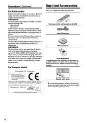
... as follows: The wire which is marked with the coloured markings identifying the terminals in the mains lead are the same regardless of color. 4 MIYAGI ONKYO EUROPE ELECTRONICS GmbH Front Left Front Left SP-B / Zone 2 Left SP-B / Zone 2 Left Front Right Front Right SP-B / Zone 2 Right SP... not correspond with the letter N or coloured black. For European Models Declaration of Conformity We, ONKYO EUROPE ELECTRONICS GmbH LIEGNITZERSTRASSE 6, 82194 GROEBENZELL, GERMANY declare in this instruction manual is not suitable for the ASTA mark or the BSI mark on the power supply cord of this...
... as follows: The wire which is marked with the coloured markings identifying the terminals in the mains lead are the same regardless of color. 4 MIYAGI ONKYO EUROPE ELECTRONICS GmbH Front Left Front Left SP-B / Zone 2 Left SP-B / Zone 2 Left Front Right Front Right SP-B / Zone 2 Right SP... not correspond with the letter N or coloured black. For European Models Declaration of Conformity We, ONKYO EUROPE ELECTRONICS GmbH LIEGNITZERSTRASSE 6, 82194 GROEBENZELL, GERMANY declare in this instruction manual is not suitable for the ASTA mark or the BSI mark on the power supply cord of this...

Owner Manual
Page 9
... speaker set B is the RT/PTY/TP button, and it's used with RDS (Radio Data System). Q TUNING MODE button (38) Selects the Auto or Manual tuning mode for composite video and analog audio. AUTO (38): For AM and FM radio, lights up when presetting radio stations. MEMORY (39): Lights up... when Auto Tuning is selected, and disappears when Manual Tuning mode is on page 40. Getting to Know the AV Receiver-Continued J TONE, [-], and [+] buttons (46) Used to specify the format of digital ...
... speaker set B is the RT/PTY/TP button, and it's used with RDS (Radio Data System). Q TUNING MODE button (38) Selects the Auto or Manual tuning mode for composite video and analog audio. AUTO (38): For AM and FM radio, lights up when presetting radio stations. MEMORY (39): Lights up... when Auto Tuning is selected, and disappears when Manual Tuning mode is on page 40. Getting to Know the AV Receiver-Continued J TONE, [-], and [+] buttons (46) Used to specify the format of digital ...

Owner Manual
Page 12
...must enter the appropriate remote control code first (see page 61 Note: Some of the remote controller operations described in this manual may not work as expected with each type of the REMOTE MODE buttons to control the compo- TV VCR CABLE SAT 2 Use ... selected by using the six REMOTE MODE buttons. ■ RECEIVER/TAPE Mode In RECEIVER/TAPE mode, you can control RECEIVER the AV receiver and an Onkyo cassette TAPE recorder connected via . 1 2 3 1 4 2 5 36 7 4 8 9 J ON/STANDBY REMOTE MODE RECEIVER DVD TAPE INPUT SELECTOR 1 2 3 V1 V2 V3 M D/CDR C D HDD 4 5 6 TV...
...must enter the appropriate remote control code first (see page 61 Note: Some of the remote controller operations described in this manual may not work as expected with each type of the REMOTE MODE buttons to control the compo- TV VCR CABLE SAT 2 Use ... selected by using the six REMOTE MODE buttons. ■ RECEIVER/TAPE Mode In RECEIVER/TAPE mode, you can control RECEIVER the AV receiver and an Onkyo cassette TAPE recorder connected via . 1 2 3 1 4 2 5 36 7 4 8 9 J ON/STANDBY REMOTE MODE RECEIVER DVD TAPE INPUT SELECTOR 1 2 3 V1 V2 V3 M D/CDR C D HDD 4 5 6 TV...
Owner Manual
Page 20
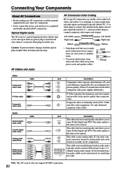
... labeled "R"). Note: The AV receiver does not support SCART connections. 20 Connecting Your Components About AV Connections • Before making any AV connections, read the manuals supplied with a 7.1channel analog audio output. Push plugs in all AV connections. It's the most common connection format for coaxial. Left (white) Analog audio Left...
... labeled "R"). Note: The AV receiver does not support SCART connections. 20 Connecting Your Components About AV Connections • Before making any AV connections, read the manuals supplied with a 7.1channel analog audio output. Push plugs in all AV connections. It's the most common connection format for coaxial. Left (white) Analog audio Left...

Owner Manual
Page 29
... page 33). • Refer to the AV receiver's TAPE IN L/R jacks. Connecting Your Components-Continued Connecting an HDD-compatible Component As of this printing, the Onkyo Remote Interactive Dock is the only HDD-compatible component available. ■ For HDD-compatible components that support video Connect your HDD-compatible component's analog audio... S jack. ■ For HDD-compatible components that don't support video Connect your HDD-compatible component's analog audio output jacks to the Remote Interactive Dock's instruction manual. 29
... page 33). • Refer to the AV receiver's TAPE IN L/R jacks. Connecting Your Components-Continued Connecting an HDD-compatible Component As of this printing, the Onkyo Remote Interactive Dock is the only HDD-compatible component available. ■ For HDD-compatible components that support video Connect your HDD-compatible component's analog audio... S jack. ■ For HDD-compatible components that don't support video Connect your HDD-compatible component's analog audio output jacks to the Remote Interactive Dock's instruction manual. 29

Owner Manual
Page 31
... components may cause a malfunction. • Some components may cause a momentary power surge that might interfere with your other -capable Onkyo components, pointing the remote controller at the AV receiver's remote control sensor instead of your speakers and AV components. • Turning... components have two jacks. Step 2: Make the connection. Similarly, when the AV receiver is set to jacks. Connecting other Onkyo components. Refer to the manuals supplied with other jack is a problem, plug the AV receiver into a different branch circuit. 31 This function will also go...
... components may cause a malfunction. • Some components may cause a momentary power surge that might interfere with your other -capable Onkyo components, pointing the remote controller at the AV receiver's remote control sensor instead of your speakers and AV components. • Turning... components have two jacks. Step 2: Make the connection. Similarly, when the AV receiver is set to jacks. Connecting other Onkyo components. Refer to the manuals supplied with other jack is a problem, plug the AV receiver into a different branch circuit. 31 This function will also go...

Owner Manual
Page 33
...the TAPE input selector or VIDEO 2 input selector, but not both at the same time. Changing the Input Display If you connect an -capable Onkyo MiniDisc recorder, CD recorder or next generation HDD-compatible component to the TAPE IN/OUT or VIDEO 2 IN jacks, for to work properly, you... output digital audio. If, for the input source that you want DVD VIDEO 1 VIDEO 2 to assign. This setting can only be assigned to the relevant manuals. 33 Note: Make sure that "TAPE" or "VIDEO2" appears on the AV receiver. 1, 2 1, 2 STANDBY/ON STANDBY PHONES TUNING PRESET MULTI CH DVD VIDEO 1 VIDEO...
...the TAPE input selector or VIDEO 2 input selector, but not both at the same time. Changing the Input Display If you connect an -capable Onkyo MiniDisc recorder, CD recorder or next generation HDD-compatible component to the TAPE IN/OUT or VIDEO 2 IN jacks, for to work properly, you... output digital audio. If, for the input source that you want DVD VIDEO 1 VIDEO 2 to assign. This setting can only be assigned to the relevant manuals. 33 Note: Make sure that "TAPE" or "VIDEO2" appears on the AV receiver. 1, 2 1, 2 STANDBY/ON STANDBY PHONES TUNING PRESET MULTI CH DVD VIDEO 1 VIDEO...
Owner Manual
Page 38
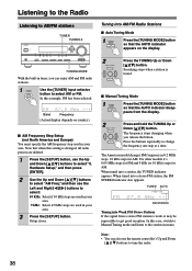
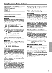
In this case, switch to Manual Tuning mode and listen to tune the radio. 38 Band Frequency (Actual display depends on the display. 2 TUNING PRESET Press the TUNING Up or Down [ ]/[ ] ... your area. 9 kHz: Select if 9 kHz steps are used in 0.2 MHz steps, 10 kHz steps for AM. Note that when this setting is found. ■ Manual Tuning Mode 1 TUNING MODE Press the [TUNING MODE] button so that the AUTO indicator appears on country.) ■ AM Frequency Step Setup (not North America...
In this case, switch to Manual Tuning mode and listen to tune the radio. 38 Band Frequency (Actual display depends on the display. 2 TUNING PRESET Press the TUNING Up or Down [ ]/[ ] ... your area. 9 kHz: Select if 9 kHz steps are used in 0.2 MHz steps, 10 kHz steps for AM. Note that when this setting is found. ■ Manual Tuning Mode 1 TUNING MODE Press the [TUNING MODE] button so that the AUTO indicator appears on country.) ■ AM Frequency Step Setup (not North America...
Owner Manual
Page 53
... . If the stereo image feels too wide, or there's too much the front left and right channels are not attenuated, maintaining the original stereo balance. Manual: You can select 0 dB (default), +5 dB, +10 dB, or +15 dB. Using the Listening Modes-Continued 4 SETUP Press the [SETUP] button. Setup closes. Use it...
... . If the stereo image feels too wide, or there's too much the front left and right channels are not attenuated, maintaining the original stereo balance. Manual: You can select 0 dB (default), +5 dB, +10 dB, or +15 dB. Using the Listening Modes-Continued 4 SETUP Press the [SETUP] button. Setup closes. Use it...
Owner Manual
Page 55
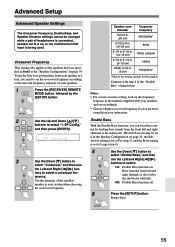
Crossover Frequency This setting only applies to the speakers that you specified as Small in the manuals supplied with step 4 of the "Double Bass" setting below. Continue with your speakers and set accordingly. • Choose a higher crossover frequency if you want more ...
Crossover Frequency This setting only applies to the speakers that you specified as Small in the manuals supplied with step 4 of the "Double Bass" setting below. Continue with your speakers and set accordingly. • Choose a higher crossover frequency if you want more ...
