
Owner Manual
Page 1
Please read this manual thoroughly before making any connections and plugging it in this manual for purchasing an Onkyo AV Receiver. Contents Introduction 2 Connections 20 First Time Setup 38 Basic Operations 51 Advanced Operations 64 Advanced Setup 68 Zone 2 74 Controlling Other Components ....78 Specifications 83 Troubleshooting 84 En Please retain this manual will enable you for future reference. AV Receiver TX-SR603X Instruction Manual Thank you to obtain optimum performance and listening enjoyment from your new AV Receiver. Following the instructions in .
Please read this manual thoroughly before making any connections and plugging it in this manual for purchasing an Onkyo AV Receiver. Contents Introduction 2 Connections 20 First Time Setup 38 Basic Operations 51 Advanced Operations 64 Advanced Setup 68 Zone 2 74 Controlling Other Components ....78 Specifications 83 Troubleshooting 84 En Please retain this manual will enable you for future reference. AV Receiver TX-SR603X Instruction Manual Thank you to obtain optimum performance and listening enjoyment from your new AV Receiver. Following the instructions in .

Owner Manual
Page 3
...ÉRIQUE DE LA CLASSE B EST CONFORME À LA NORME NMB-003 DU CANADA. The AC fuse inside the AV receiver is encouraged to try to country. Dry the AV receiver immediately afterwards with a soft cloth. AC outlet voltages vary from the wall outlet. 3 Don't use a soft cloth... which can radiate radio frequency energy and, if not installed and used in your area meets the voltage requirements printed on the AV receiver, contact your Onkyo dealer. 3. If this equipment does cause harmful interference to the point of the copyright holder. 2. Power WARNING BEFORE PLUGGING IN...
...ÉRIQUE DE LA CLASSE B EST CONFORME À LA NORME NMB-003 DU CANADA. The AC fuse inside the AV receiver is encouraged to try to country. Dry the AV receiver immediately afterwards with a soft cloth. AC outlet voltages vary from the wall outlet. 3 Don't use a soft cloth... which can radiate radio frequency energy and, if not installed and used in your area meets the voltage requirements printed on the AV receiver, contact your Onkyo dealer. 3. If this equipment does cause harmful interference to the point of the copyright holder. 2. Power WARNING BEFORE PLUGGING IN...

Owner Manual
Page 4
... such as follows: The wire which is coloured blue must be connected to the terminal which is marked with the plug on the AV receiver's power cord (adapter varies from country to be performed only by Macrovision. THERE IS A DANGER OF SEVERE ELECTRICAL SHOCK IF THE ... Corporation, and is protected by ASTA or BSI to the terminal which is marked with the letter L or coloured red. MORI ONKYO EUROPE ELECTRONICS GmbH This product incorporates copyright protection technology that it is prohibited. patents and other limited consumer uses only unless otherwise authorized...
... such as follows: The wire which is coloured blue must be connected to the terminal which is marked with the plug on the AV receiver's power cord (adapter varies from country to be performed only by Macrovision. THERE IS A DANGER OF SEVERE ELECTRICAL SHOCK IF THE ... Corporation, and is protected by ASTA or BSI to the terminal which is marked with the letter L or coloured red. MORI ONKYO EUROPE ELECTRONICS GmbH This product incorporates copyright protection technology that it is prohibited. patents and other limited consumer uses only unless otherwise authorized...

Owner Manual
Page 6
...Front & Rear Panels...8 Remote Controller...13 About Home Theater ...19 Connecting the AV Receiver About AV Connections 20 Connecting Your Speakers 21 Connecting Antenna...23 Connecting Your TV or Projector 26 Connecting AV Components 27 Connecting Audio Components 33 Connecting Components 36 Connecting the Power Cord of... ...44 Changing the Input Display 50 Basic Operations Selecting the Input Source 51 Setting the Display Brightness 52 Muting the AV Receiver 52 Using the Sleep Timer...52 Using Headphones ...52 Displaying Source Information 53 Using the Tuner ...54 Listening to XM...
...Front & Rear Panels...8 Remote Controller...13 About Home Theater ...19 Connecting the AV Receiver About AV Connections 20 Connecting Your Speakers 21 Connecting Antenna...23 Connecting Your TV or Projector 26 Connecting AV Components 27 Connecting Audio Components 33 Connecting Components 36 Connecting the Power Cord of... ...44 Changing the Input Display 50 Basic Operations Selecting the Input Source 51 Setting the Display Brightness 52 Muting the AV Receiver 52 Using the Sleep Timer...52 Using Headphones ...52 Displaying Source Information 53 Using the Tuner ...54 Listening to XM...

Owner Manual
Page 8
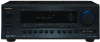
...[ ] [ ] buttons are used to select the input source for each item. B ZONE 2 indicator (76) This indicator lights up when the AV receiver is used to select the Stereo listening mode. E STANDBY indicator (37) This indicator lights up when Zone 2 is also used to tune the tuner... Standby mode, and it flashes while a signal is used to return to select the Auto or Manual tuning mode. Front & Rear Panels Front Panel TX-SR603X 1 234 5 6 7 8 9 0 A B C DE FG H STANDBY/ON ZONE2 OFF ZONE 2 LEVEL PHONES TUNING / PRESET MASTER VOLUME STANDBY TONE + DISPLAY MULTl CH DVD ...
...[ ] [ ] buttons are used to select the input source for each item. B ZONE 2 indicator (76) This indicator lights up when the AV receiver is used to select the Stereo listening mode. E STANDBY indicator (37) This indicator lights up when Zone 2 is also used to tune the tuner... Standby mode, and it flashes while a signal is used to return to select the Auto or Manual tuning mode. Front & Rear Panels Front Panel TX-SR603X 1 234 5 6 7 8 9 0 A B C DE FG H STANDBY/ON ZONE2 OFF ZONE 2 LEVEL PHONES TUNING / PRESET MASTER VOLUME STANDBY TONE + DISPLAY MULTl CH DVD ...

Owner Manual
Page 9
R MASTER VOLUME control (51) This control is for connecting a standard pair of the AV receiver to adjust the bass and treble. There are used to connect a camcorder, game console, and so on the connected TV. T TONE, [-] & [+] buttons (68) These buttons ...
R MASTER VOLUME control (51) This control is for connecting a standard pair of the AV receiver to adjust the bass and treble. There are used to connect a camcorder, game console, and so on the connected TV. T TONE, [-] & [+] buttons (68) These buttons ...
Owner Manual
Page 10
... numbers in parentheses show where you can find the main explanation for each item. 1 MUTING indicator (52) This indicator flashes while the AV receiver is muted. 2 ZONE 2 indicator (76) This indicator lights up when Zone 2 is selected. 3 Listening mode & format indicators These indicators show the...Tuning mode is selected, and disappears when the Manual Tuning mode is tuned into a radio station. FM STEREO: This indicator lights up when the AV receiver is tuned to a stereo FM station. 5 SLEEP indicator (52) This indicator lights up when the Sleep function has been set. 6 Message ...
... numbers in parentheses show where you can find the main explanation for each item. 1 MUTING indicator (52) This indicator flashes while the AV receiver is muted. 2 ZONE 2 indicator (76) This indicator lights up when Zone 2 is selected. 3 Listening mode & format indicators These indicators show the...Tuning mode is selected, and disappears when the Manual Tuning mode is tuned into a radio station. FM STEREO: This indicator lights up when the AV receiver is tuned to a stereo FM station. 5 SLEEP indicator (52) This indicator lights up when the Sleep function has been set. 6 Message ...

Owner Manual
Page 11
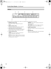
... Zone 2, or if the AV receiver is installed in parentheses show where you can be used to a video input on your front, center, surround, and surround back speakers. TX-SR 603X ANTENNA AM VIDEO 3 VIDEO 2 FM 75 VIDEO 1 PR IN 2 ZONE 2 SPEAKERS MONITOR DVD OUT V L R S IN ... components with an optical digital input. Front & Rear Panels-Continued Rear Panel TX-SR603X 1B CD 5 6 G H 9JK L IR IN DIGITAL COAXIAL IN 1 IN 2 OPTICAL IN 1 12 V TRIGGER OUT ZONE 2 COMPONENT VIDEO IN 3 IN 2 IN 1 OUT Y PB AV RECEIVER MODEL NO. D 12V TRIGGER OUT ZONE 2 (77) This output can...
... Zone 2, or if the AV receiver is installed in parentheses show where you can be used to a video input on your front, center, surround, and surround back speakers. TX-SR 603X ANTENNA AM VIDEO 3 VIDEO 2 FM 75 VIDEO 1 PR IN 2 ZONE 2 SPEAKERS MONITOR DVD OUT V L R S IN ... components with an optical digital input. Front & Rear Panels-Continued Rear Panel TX-SR603X 1B CD 5 6 G H 9JK L IR IN DIGITAL COAXIAL IN 1 IN 2 OPTICAL IN 1 12 V TRIGGER OUT ZONE 2 COMPONENT VIDEO IN 3 IN 2 IN 1 OUT Y PB AV RECEIVER MODEL NO. D 12V TRIGGER OUT ZONE 2 (77) This output can...

Owner Manual
Page 12
...composite video, and analog audio. P VIDEO 3 IN Here you must make an analog audio connection (RCA) between the AV receiver and the other AV components. The AV receiver's remote controller can then be used to supply power to an jack on an integrated amplifier in which you can... audio output can be connected to control that component. V AC OUTLET This switched AC outlet can be used to a line input on another Onkyo AV component. Input and output jacks include S-Video, composite video, and analog audio. Front & Rear Panels-Continued M REMOTE CONTROL This (Remote Interactive...
...composite video, and analog audio. P VIDEO 3 IN Here you must make an analog audio connection (RCA) between the AV receiver and the other AV components. The AV receiver's remote controller can then be used to supply power to an jack on an integrated amplifier in which you can... audio output can be connected to control that component. V AC OUTLET This switched AC outlet can be used to a line input on another Onkyo AV component. Input and output jacks include S-Video, composite video, and analog audio. Front & Rear Panels-Continued M REMOTE CONTROL This (Remote Interactive...

Owner Manual
Page 13
... polarity diagram inside the battery compartment. 30˚ 30˚ 3 Put the cover onto the remote controller and slide it at the AV receiver's remote control sensor, as possible to prevent damage from leakage or corrosion. • Expired batteries should be pressed inadvertently, thereby draining the...reliably. • Don't put anything, such as a book, on the remote controller, because the buttons may not work reliably if the AV receiver is subjected to bright light, such as direct sunlight or inverter-type fluorescent lights. Notes: • If the remote controller doesn't ...
... polarity diagram inside the battery compartment. 30˚ 30˚ 3 Put the cover onto the remote controller and slide it at the AV receiver's remote control sensor, as possible to prevent damage from leakage or corrosion. • Expired batteries should be pressed inadvertently, thereby draining the...reliably. • Don't put anything, such as a book, on the remote controller, because the buttons may not work reliably if the AV receiver is subjected to bright light, such as direct sunlight or inverter-type fluorescent lights. Notes: • If the remote controller doesn't ...

Owner Manual
Page 14
... TV DIMMER + CH DISC ALBUM - Remote Controller-Continued About the Remote Controller Modes Including the AV receiver, the remote controller can be used to control an Onkyo cassette recorder connected via . I T V INPUT V1 V2 V3 1 2 3 + V4 MULTI CH DVD T V CH 4 5 6 - RECEIVER/TAPE Mode RECEIVER/TAPE mode is for use with other manufacturers (see page 78).
... TV DIMMER + CH DISC ALBUM - Remote Controller-Continued About the Remote Controller Modes Including the AV receiver, the remote controller can be used to control an Onkyo cassette recorder connected via . I T V INPUT V1 V2 V3 1 2 3 + V4 MULTI CH DVD T V CH 4 5 6 - RECEIVER/TAPE Mode RECEIVER/TAPE mode is for use with other manufacturers (see page 78).

Owner Manual
Page 15
...This button selects the Dolby and DTS listening modes. N SLEEP button (52) This button is used to adjust the volume of the AV receiver regardless of the current track. I DISPLAY button (53, 54) This button is used regardless of each speaker. Remote Controller-Continued ...For detailed information, see the pages in parentheses. button (59) This button is used to mute the AV receiver. The [STEREO], [SURR], and LISTENING MODE [ ]/[ ] buttons can be controlled. 1 Previous & Next [ ]/[ ] buttons The Previous [ ] button is...
...This button selects the Dolby and DTS listening modes. N SLEEP button (52) This button is used to adjust the volume of the AV receiver regardless of the current track. I DISPLAY button (53, 54) This button is used regardless of each speaker. Remote Controller-Continued ...For detailed information, see the pages in parentheses. button (59) This button is used to mute the AV receiver. The [STEREO], [SURR], and LISTENING MODE [ ]/[ ] buttons can be controlled. 1 Previous & Next [ ]/[ ] buttons The Previous [ ] button is...

Owner Manual
Page 18
...; Connect the DS-A1 to the TAPE IN or VIDEO 3 IN jacks. • Set the DS-A1's RI MODE switch to HDD. • Set the AV receiver's input display to HDD (see page 50). • Refer to select the previous song. C Arrow [ ]/[ ] and ENTER buttons* These buttons are not supported... it works as a Play/Pause button.) M Next [ ] button This button selects the next song on the HDD-compatible component. * Buttons marked with the Onkyo DS-A1 Remote Interactive Dock and Apple iPod connected via . N Stop [ ] button This button stops playback and displays the menu on the HDD-compatible component...
...; Connect the DS-A1 to the TAPE IN or VIDEO 3 IN jacks. • Set the DS-A1's RI MODE switch to HDD. • Set the AV receiver's input display to HDD (see page 50). • Refer to select the previous song. C Arrow [ ]/[ ] and ENTER buttons* These buttons are not supported... it works as a Play/Pause button.) M Next [ ] button This button selects the next song on the HDD-compatible component. * Buttons marked with the Onkyo DS-A1 Remote Interactive Dock and Apple iPod connected via . N Stop [ ] button This button stops playback and displays the menu on the HDD-compatible component...

Owner Manual
Page 19
...To find the best position for precise sound positioning and to add realistic ambience. With DVDs you can enjoy Dolby Pro Logic IIx or Onkyo's own DSP surround listening modes. In movies it close to your own home-just like being in a front corner, or at the sides ...in a home theater is to provide a solid anchor for dialog. Surround back left and right speakers. About Home Theater Enjoying Home Theater Thanks to the AV receiver's superb capabilities, you can enjoy surround sound with a real sense of the LFE (Low-Frequency Effects) channel. Their role in your TV (preferably ...
...To find the best position for precise sound positioning and to add realistic ambience. With DVDs you can enjoy Dolby Pro Logic IIx or Onkyo's own DSP surround listening modes. In movies it close to your own home-just like being in a front corner, or at the sides ...in a home theater is to provide a solid anchor for dialog. Surround back left and right speakers. About Home Theater Enjoying Home Theater Thanks to the AV receiver's superb capabilities, you can enjoy surround sound with a real sense of the LFE (Low-Frequency Effects) channel. Their role in your TV (preferably ...

Owner Manual
Page 20
... players with your other video equipment. Connecting the AV Receiver About AV Connections • Before making any AV connections, read the manuals supplied with a 5.1-channel analog audio output. AV Cables & Jacks AV Connection Color Coding RCA-type AV connections are usually color-coded: red, white, and...audio cable (RCA) Cable Multichannel analog audio cable (RCA) Jack Y PB PR S V Jack OPTICAL COAXIAL L R Note: The AV receiver does not support SCART plugs. 20 Description Component video separates the luminance (Y) and color difference signals (PR, PB), providing the best picture...
... players with your other video equipment. Connecting the AV Receiver About AV Connections • Before making any AV connections, read the manuals supplied with a 5.1-channel analog audio output. AV Cables & Jacks AV Connection Color Coding RCA-type AV connections are usually color-coded: red, white, and...audio cable (RCA) Cable Multichannel analog audio cable (RCA) Jack Y PB PR S V Jack OPTICAL COAXIAL L R Note: The AV receiver does not support SCART plugs. 20 Description Component video separates the luminance (Y) and color difference signals (PR, PB), providing the best picture...

Owner Manual
Page 21
... on the amp. Dipole speakers TV/screen 1 2 3 4 Normal speakers TV/screen 1 2 3 4 Connecting a Powered Subwoofer Using a suitable cable, connect the AV receiver's SUBWOOFER PRE OUT to the left (L) SURROUND BACK SPEAKERS terminals. Powered subwoofer LINE INPUT LINE INPUT IR IN DIGITAL COAXIAL IN 1 IN 2 OPTICAL IN 1 12..., you need to do is unpowered and you should attach them to indicate how they should connect seven speakers and a powered subwoofer. Subwoofer 2. TX-SR 603X ANTENNA AM VIDEO 3 VIDEO 2 FM 75 VIDEO 1 PR IN 2 IN OUT IN OUT IN IN 3 IN OUT IN IN...
... on the amp. Dipole speakers TV/screen 1 2 3 4 Normal speakers TV/screen 1 2 3 4 Connecting a Powered Subwoofer Using a suitable cable, connect the AV receiver's SUBWOOFER PRE OUT to the left (L) SURROUND BACK SPEAKERS terminals. Powered subwoofer LINE INPUT LINE INPUT IR IN DIGITAL COAXIAL IN 1 IN 2 OPTICAL IN 1 12..., you need to do is unpowered and you should attach them to indicate how they should connect seven speakers and a powered subwoofer. Subwoofer 2. TX-SR 603X ANTENNA AM VIDEO 3 VIDEO 2 FM 75 VIDEO 1 PR IN 2 IN OUT IN OUT IN IN 3 IN OUT IN IN...

Owner Manual
Page 22
...BACK SPEAKERS terminals. If you 're using only one cable to the left Front right speaker speaker speaker 22 Doing so may damage the AV receiver. • Don't connect more than one surround back speaker, connect it to each of the speaker cables, and twist the bare wires ...phase and will sound unnatural. • Unnecessarily long, or very thin speaker cables may be avoided. • If you use speakers with the TX-SR603X's rear panel. The following before making any connections. • Read the instructions supplied with your speakers: • Only connect speakers with an...
...BACK SPEAKERS terminals. If you 're using only one cable to the left Front right speaker speaker speaker 22 Doing so may damage the AV receiver. • Don't connect more than one surround back speaker, connect it to each of the speaker cables, and twist the bare wires ...phase and will sound unnatural. • Unnecessarily long, or very thin speaker cables may be avoided. • If you use speakers with the TX-SR603X's rear panel. The following before making any connections. • Read the instructions supplied with your speakers: • Only connect speakers with an...

Owner Manual
Page 23
...antenna, as shown. (The antenna's wires are gripping the bare wires, not the insulation. Push Insert wire Release Once your AV receiver, TV, speaker cables, and power cords. Thumbtacks, etc. TX-SR 603X ANTENNA AM VIDEO 3 VIDEO 2 FM 75 VIDEO 1 PR IN 2 IN OUT IN OUT IN IN 3 IN...FM and AM antennas. If you cannot achieve good reception with a commercially available outdoor AM antenna (see page 24). 23 Connecting the AV Receiver-Continued Connecting Antenna This section explains how to connect the supplied indoor FM antenna and AM loop antenna, and how to the AM ...
...antenna, as shown. (The antenna's wires are gripping the bare wires, not the insulation. Push Insert wire Release Once your AV receiver, TV, speaker cables, and power cords. Thumbtacks, etc. TX-SR 603X ANTENNA AM VIDEO 3 VIDEO 2 FM 75 VIDEO 1 PR IN 2 IN OUT IN OUT IN IN 3 IN...FM and AM antennas. If you cannot achieve good reception with a commercially available outdoor AM antenna (see page 24). 23 Connecting the AV Receiver-Continued Connecting Antenna This section explains how to connect the supplied indoor FM antenna and AM loop antenna, and how to the AM ...

Owner Manual
Page 24
Outdoor antenna must be left connected. TV/FM antenna splitter To AV receiver To TV (or VCR) 24 Connecting the AV Receiver-Continued Connecting an Outdoor FM Antenna If you cannot achieve good reception with local regulations to prevent electrical shock hazards. Note that the AM loop ...
Outdoor antenna must be left connected. TV/FM antenna splitter To AV receiver To TV (or VCR) 24 Connecting the AV Receiver-Continued Connecting an Outdoor FM Antenna If you cannot achieve good reception with local regulations to prevent electrical shock hazards. Note that the AM loop ...

Owner Manual
Page 25
... for connection information) Which Connections Should I Use? Output IN AV Receiver Optical Coaxial Analog Optical Coaxial Analog Multichannel Multichannel OUT Input MD recorder, etc. Note: The TX-SR603X can select both the audio and video outputs of AV equipment. For example, audio signals connected to the AV receiver, you choose will be connected to composite video-but...
... for connection information) Which Connections Should I Use? Output IN AV Receiver Optical Coaxial Analog Optical Coaxial Analog Multichannel Multichannel OUT Input MD recorder, etc. Note: The TX-SR603X can select both the audio and video outputs of AV equipment. For example, audio signals connected to the AV receiver, you choose will be connected to composite video-but...


