
Owner Manual
Page 1
AV Receiver TX-SR701/701E TX-SR601/601E Instruction Manual Contents Before using 2 Facilities and connections 8 Setup and operation 31 Thank you to obtain optimum performance and listening enjoyment from your new AV Receiver. Remote controller 63 Appendix 75 En Please retain this manual thoroughly before making connections and plugging in this manual will enable you for future reference. Please read this manual for purchasing the Onkyo AV Receiver. Following the instructions in the unit.
AV Receiver TX-SR701/701E TX-SR601/601E Instruction Manual Contents Before using 2 Facilities and connections 8 Setup and operation 31 Thank you to obtain optimum performance and listening enjoyment from your new AV Receiver. Remote controller 63 Appendix 75 En Please retain this manual thoroughly before making connections and plugging in this manual will enable you for future reference. Please read this manual for purchasing the Onkyo AV Receiver. Following the instructions in the unit.

Owner Manual
Page 7
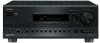
... DIGITAL IN OUT OPTICAL 2 1 OPTICAL COAXIAL VIDEO 3 IN VIDEO 2 OUT IN IN GND L IN COAXIAL IN OUT IN IN OUT IN R VIDEO 1 OUT IN DVD IN REMOTE R CONTROL MONITOR OUT V ZONE 2 12 V TRIGGER OUT R ZONE 2 FRONT S IR IN L AV RECEIVER MODEL NO. Remote control sensor TX-SR701... interference. • Do not put objects on the remote controller. The STANDBY indicator lights up when the unit receives a signal from corrosion. Placing the TX-SR701/701E/601/601E behind such doors may prevent proper remote controller operation. • If there is appropriate. Supplied ...
... DIGITAL IN OUT OPTICAL 2 1 OPTICAL COAXIAL VIDEO 3 IN VIDEO 2 OUT IN IN GND L IN COAXIAL IN OUT IN IN OUT IN R VIDEO 1 OUT IN DVD IN REMOTE R CONTROL MONITOR OUT V ZONE 2 12 V TRIGGER OUT R ZONE 2 FRONT S IR IN L AV RECEIVER MODEL NO. Remote control sensor TX-SR701... interference. • Do not put objects on the remote controller. The STANDBY indicator lights up when the unit receives a signal from corrosion. Placing the TX-SR701/701E/601/601E behind such doors may prevent proper remote controller operation. • If there is appropriate. Supplied ...

Owner Manual
Page 15
... speakers [26] AC OUTLETS [24] ANTENNA AM COMPONENT VIDEO INPUT 2 INPUT 1 OUTPUT Y PB FM 75 ZONE 2 LINE OUT L ZONE 2 SPEAKERS L PR DIGITAL IN OUT OPTICAL 2 1 OPTICAL VIDEO 3 IN IN COAXIAL VIDEO 2 OUT IN R VIDEO 1 OUT IN DVD IN REMOTE R CONTROL MONITOR OUT V ZONE 2 ...SPEAKERS L CENTER SPEAKER AC OUTLETS R SURROUND BACK PRE OUT SPEAKER SUBWOOFER AC 230-240V 50 Hz SWITCHED TOTAL 100W MAX. AV RECEIVER MODEL NO. Connections TX-SR701/701E Connecting antennas [29] COMPONENT VIDEO INPUT/OUTPUT [18-20] When using REMOTE the Zone 2 CONTROL [24] LINE ...
... speakers [26] AC OUTLETS [24] ANTENNA AM COMPONENT VIDEO INPUT 2 INPUT 1 OUTPUT Y PB FM 75 ZONE 2 LINE OUT L ZONE 2 SPEAKERS L PR DIGITAL IN OUT OPTICAL 2 1 OPTICAL VIDEO 3 IN IN COAXIAL VIDEO 2 OUT IN R VIDEO 1 OUT IN DVD IN REMOTE R CONTROL MONITOR OUT V ZONE 2 ...SPEAKERS L CENTER SPEAKER AC OUTLETS R SURROUND BACK PRE OUT SPEAKER SUBWOOFER AC 230-240V 50 Hz SWITCHED TOTAL 100W MAX. AV RECEIVER MODEL NO. Connections TX-SR701/701E Connecting antennas [29] COMPONENT VIDEO INPUT/OUTPUT [18-20] When using REMOTE the Zone 2 CONTROL [24] LINE ...

Owner Manual
Page 27
... the audio will sound unnatural. • Do not connect more than 6 Ω may damage the TX-SR701/701E/601/ 601E. • Connect only speakers with an impedance lower than one speaker cable to one...AM COMPONENT VIDEO INPUT 2 INPUT 1 OUTPUT Y PB FM 75 ZONE 2 LINE OUT L ZONE 2 SPEAKERS L PR DIGITAL IN OUT OPTICAL 2 1 OPTICAL VIDEO 3 COAXIAL IN VIDEO 2 OUT IN IN GND L IN COAXIAL IN OUT IN...AC 230-240V 50 Hz SWITCHED TOTAL 100W MAX. SUB WOOFER R AV RECEIVER MODEL NO. Twist the wire ends tightly together. 3. If they are using only one speaker terminal.
... the audio will sound unnatural. • Do not connect more than 6 Ω may damage the TX-SR701/701E/601/ 601E. • Connect only speakers with an impedance lower than one speaker cable to one...AM COMPONENT VIDEO INPUT 2 INPUT 1 OUTPUT Y PB FM 75 ZONE 2 LINE OUT L ZONE 2 SPEAKERS L PR DIGITAL IN OUT OPTICAL 2 1 OPTICAL VIDEO 3 COAXIAL IN VIDEO 2 OUT IN IN GND L IN COAXIAL IN OUT IN...AC 230-240V 50 Hz SWITCHED TOTAL 100W MAX. SUB WOOFER R AV RECEIVER MODEL NO. Twist the wire ends tightly together. 3. If they are using only one speaker terminal.


