

Owner Manual
Page 1
ON KILTO TX-SV444 Audio Video Control Receiver 1 - Audio Video Karaoke Control Receiver Instruction Manual O O CONTENTS Features 2 Important Safeguards 3 Precautions 4 Supplied accessories 4 Setting the voltage selector and tuning step frequency...connections 7 Video equipment connections 8 Making speakers connections 10 Speaker placement 11 Making antenna connections 12 Connecting Onkyo components for R I operation 14 Basic operations 15 Receiving stations 18 Using preset stations 19 Use of surround mode 20 Parameter selector 20 Setting the surround ...
ON KILTO TX-SV444 Audio Video Control Receiver 1 - Audio Video Karaoke Control Receiver Instruction Manual O O CONTENTS Features 2 Important Safeguards 3 Precautions 4 Supplied accessories 4 Setting the voltage selector and tuning step frequency...connections 7 Video equipment connections 8 Making speakers connections 10 Speaker placement 11 Making antenna connections 12 Connecting Onkyo components for R I operation 14 Basic operations 15 Receiving stations 18 Using preset stations 19 Use of surround mode 20 Parameter selector 20 Setting the surround ...
Owner Manual
Page 2
...listening enjoyment from your plug, proceed as close to the point of the FCC Rules. Please read this manual for purchasing the Onkyo Audio Video Control Receiver. Features • 70 Watts per channel into an outlet on whole system with the coloured markings identifying the terminals in the ...CANADIAN MODEL POUR LE MODELE CANADIEN • For models having a power cord with 2 mic inputs, voice cancel, pitch, echo and separate volume controls (TX-SE500) • Dolby- TRIQUES, INTRODUIRE LA LAME LA PLUS LARGE DE LA FICHE DANS LA BORNE CORRESPONDANTE DE LA PRISE ET POUSSER JUSQU' AU FOND...
...listening enjoyment from your plug, proceed as close to the point of the FCC Rules. Please read this manual for purchasing the Onkyo Audio Video Control Receiver. Features • 70 Watts per channel into an outlet on whole system with the coloured markings identifying the terminals in the ...CANADIAN MODEL POUR LE MODELE CANADIEN • For models having a power cord with 2 mic inputs, voice cancel, pitch, echo and separate volume controls (TX-SE500) • Dolby- TRIQUES, INTRODUIRE LA LAME LA PLUS LARGE DE LA FICHE DANS LA BORNE CORRESPONDANTE DE LA PRISE ET POUSSER JUSQU' AU FOND...
Owner Manual
Page 3
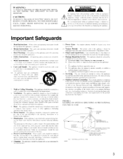
... one blade wider than the other. Damage Requiring Service The appliance should not he fol lowed. Servicing - If an outside antenna is connected to the receiver, he sure the antenna system is intended to alert the user to provide some protection against them, especially near water - FIGURE I . within the product's enclosure...
... one blade wider than the other. Damage Requiring Service The appliance should not he fol lowed. Servicing - If an outside antenna is connected to the receiver, he sure the antenna system is intended to alert the user to provide some protection against them, especially near water - FIGURE I . within the product's enclosure...
Owner Manual
Page 5
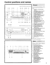
...Control positions and names 3 4 56 ON 1 24 23 25 26 27 0243[1(0 09 29 28 Model TX-SV444 front panel shown 7 8 9 10 11 12 13 14 22 21 20 1918 17 16 15 Model TX-SE500 front panel shown o o Front panel For more information about buttons or knobs, refer to read the... knob [15, 21, 24] 15. TREBLE control knob [15, 16] 17. 3-D BASS button [15, 16] 18. Audio Mute indicator g. 3-D Bass indicator h. RDS station received indicator (European model only) 1. Remote control sensor [6, 14] 6. TUNING UP/DOWN buttons [18] 8. FM MUTE/MODE button [18, 19] 21. MIC jacks /241 NOTE:...
...Control positions and names 3 4 56 ON 1 24 23 25 26 27 0243[1(0 09 29 28 Model TX-SV444 front panel shown 7 8 9 10 11 12 13 14 22 21 20 1918 17 16 15 Model TX-SE500 front panel shown o o Front panel For more information about buttons or knobs, refer to read the... knob [15, 21, 24] 15. TREBLE control knob [15, 16] 17. 3-D BASS button [15, 16] 18. Audio Mute indicator g. 3-D Bass indicator h. RDS station received indicator (European model only) 1. Remote control sensor [6, 14] 6. TUNING UP/DOWN buttons [18] 8. FM MUTE/MODE button [18, 19] 21. MIC jacks /241 NOTE:...
Owner Manual
Page 6
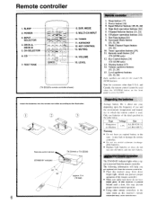
...LR6 (AM-3) Warning • Do not leave an expired battery in the same room as this receiver's remote controller may cause interference. do not use one old battery and one year, depending upon the... at once; POWER 3. DECK-A, DECK-B 5. n ' o on the front panel is about one new battery. I o LI) O ONKYO HEW, COP.'S LEP 8. MODE 9. KEY CONTROL 13. Sleep button [17] 2. Input Selector buttons [15, 21, 24] 4. Test Tone...control sensor STAND-BY indicator 30' TX-SV444 or TX-SE500 approx. 5 m (16 feet) 6 Regarding the batteries Average battery life is set to the illustration...
...LR6 (AM-3) Warning • Do not leave an expired battery in the same room as this receiver's remote controller may cause interference. do not use one old battery and one year, depending upon the... at once; POWER 3. DECK-A, DECK-B 5. n ' o on the front panel is about one new battery. I o LI) O ONKYO HEW, COP.'S LEP 8. MODE 9. KEY CONTROL 13. Sleep button [17] 2. Input Selector buttons [15, 21, 24] 4. Test Tone...control sensor STAND-BY indicator 30' TX-SV444 or TX-SE500 approx. 5 m (16 feet) 6 Regarding the batteries Average battery life is set to the illustration...

Owner Manual
Page 7
PUT SL, .{I D e CENTER SPEAKER rri See gt; 1 Audio equipment connections • On each pair of input jacks, the lower jack (marked R, red) corresponds to the right channel, and the upper jack (marked L, white) to the left channel. • Please refer to the instruction manual of each component when making any connections. • This receiver is designed for use with turntables using moving magnet cartridges. Turntable 0 PHONO OUT U MULTI.
PUT SL, .{I D e CENTER SPEAKER rri See gt; 1 Audio equipment connections • On each pair of input jacks, the lower jack (marked R, red) corresponds to the right channel, and the upper jack (marked L, white) to the left channel. • Please refer to the instruction manual of each component when making any connections. • This receiver is designed for use with turntables using moving magnet cartridges. Turntable 0 PHONO OUT U MULTI.
Owner Manual
Page 8
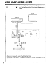
... Video Disc Player I I I AUDIO OUT VIDEO OUT Monitor TV VIDEO IN ti 43 0 0 0 0 CENTER SPEAKER .„,NTOR IDL P0NT SPE.... If this receiver. Video equipment connections • On each pair of input jacks, the lower jack (marked R, red) corresponds to the right channel, and the upper jack (marked... L, white) to the left channel. • Please refer to make the output connections. • This receiver can be used with only a monitor TV equipped with a video input jack. • Interference may be caused between the TV and this interference occurs...
... Video Disc Player I I I AUDIO OUT VIDEO OUT Monitor TV VIDEO IN ti 43 0 0 0 0 CENTER SPEAKER .„,NTOR IDL P0NT SPE.... If this receiver. Video equipment connections • On each pair of input jacks, the lower jack (marked R, red) corresponds to the right channel, and the upper jack (marked... L, white) to the left channel. • Please refer to make the output connections. • This receiver can be used with only a monitor TV equipped with a video input jack. • Interference may be caused between the TV and this interference occurs...
Owner Manual
Page 9
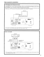
...IN MA.11{11.11 0 0 z O0 O O141,,I1 :6) 0 :§) 0 REAP PP EPS 10 0 [0 • This receiver will automatically switch on approximately three to five seconds after the TV is used in this receiver also switches on automatically and the input selector is shown on the display, the IPM function cannot...OUT SUBWOOFER OUT CENTER OUT GI 0 O6O 000 0,000)8 PEP P - Provided that the input selector remains set the SPEAKERS B button to TV, the receiver will be used , connect the audio output of a monitor TV to TV. Then, press the TV/AUX button until "IPM ON" appears on the front...
...IN MA.11{11.11 0 0 z O0 O O141,,I1 :6) 0 :§) 0 REAP PP EPS 10 0 [0 • This receiver will automatically switch on approximately three to five seconds after the TV is used in this receiver also switches on automatically and the input selector is shown on the display, the IPM function cannot...OUT SUBWOOFER OUT CENTER OUT GI 0 O6O 000 0,000)8 PEP P - Provided that the input selector remains set the SPEAKERS B button to TV, the receiver will be used , connect the audio output of a monitor TV to TV. Then, press the TV/AUX button until "IPM ON" appears on the front...

Owner Manual
Page 10
... rear speakers Front Speakers A R ch. For best results, connect a center speaker. • Use FRONT SPEAKERS B terminals to connect a second pair of front speakers. • This receiver is designed to circuitry, never short-circuit the positive (+) and negative (-) speaker wire. 44 NO FRONT SPEAKERS A or B : 6 ohms min./speaker A + B : 12 ohms min./speaker...
... rear speakers Front Speakers A R ch. For best results, connect a center speaker. • Use FRONT SPEAKERS B terminals to connect a second pair of front speakers. • This receiver is designed to circuitry, never short-circuit the positive (+) and negative (-) speaker wire. 44 NO FRONT SPEAKERS A or B : 6 ohms min./speaker A + B : 12 ohms min./speaker...
Owner Manual
Page 12
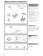
... same antenna for both FM and TV (or VCR) reception since the FM and TV (or VCR) signals can interfere with each other. With your receiver is a worldwide model. Directional linkage type splitter To TX-SV444/TX-SE500 To TV (or VCR) 1 O Insert into slit C. 3.
... same antenna for both FM and TV (or VCR) reception since the FM and TV (or VCR) signals can interfere with each other. With your receiver is a worldwide model. Directional linkage type splitter To TX-SV444/TX-SE500 To TV (or VCR) 1 O Insert into slit C. 3.
Owner Manual
Page 13
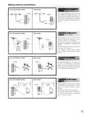
... FM outdoor antenna If the reception is not very clear with push pins or similar in various directions until the clearest signal is received. Please make sure that you receive the clearest sound. Keep the antenna away from the main unit, TV set, speaker cords and power cord. Connecting the AM loop...
... FM outdoor antenna If the reception is not very clear with push pins or similar in various directions until the clearest signal is received. Please make sure that you receive the clearest sound. Keep the antenna away from the main unit, TV set, speaker cords and power cord. Connecting the AM loop...
Owner Manual
Page 14
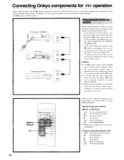
...Dy, r=r-, r-Th 0 CH.SEL • f II I O ONICV0 , O When you have the Onkyo RI mark can connect from this receiver. CD player operation buttons (CD) DISC : Disc button for remote control (RI) TX-SV444 or TX-SE500 0 0 0 RI CD Player RI I I Cassette Tape Deck RI _1 1 0 o o ...o 0 When connecting Onkyo products, you will be connected. Tape deck operation ...
...Dy, r=r-, r-Th 0 CH.SEL • f II I O ONICV0 , O When you have the Onkyo RI mark can connect from this receiver. CD player operation buttons (CD) DISC : Disc button for remote control (RI) TX-SV444 or TX-SE500 0 0 0 RI CD Player RI I I Cassette Tape Deck RI _1 1 0 o o ...o 0 When connecting Onkyo products, you will be connected. Tape deck operation ...
Owner Manual
Page 15
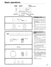
... level using the MASTER VOLUME control or VOLUME A(up)/Y(down) buttons on the display. Set the volume to the "Speakers selector" on this receiver's power may cause a momentary power surge, which might interfere with other electrical equipment, such as computers. Insert the AC power supply cord into... AC outlet POWER PT AND BYO)", (U.S. & Canadian models) or SYSTEM • ON • OP, (Other models) Connecting the power Before plugging in the receiver, confirm that the TAPE MON. If the indicator is off the TAPE MON. Confirm that all connections have been made properly.
... level using the MASTER VOLUME control or VOLUME A(up)/Y(down) buttons on the display. Set the volume to the "Speakers selector" on this receiver's power may cause a momentary power surge, which might interfere with other electrical equipment, such as computers. Insert the AC power supply cord into... AC outlet POWER PT AND BYO)", (U.S. & Canadian models) or SYSTEM • ON • OP, (Other models) Connecting the power Before plugging in the receiver, confirm that the TAPE MON. If the indicator is off the TAPE MON. Confirm that all connections have been made properly.
Owner Manual
Page 16
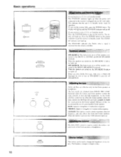
... B indicator lights up . Basic operations POWER STAND•BY'ON - 8TAND-BY POWER O y~lo off the speakers connected to put the receiver in Standby mode, ready for operation. Adjusting the balance The BALANCE control is pressed, the 3-DB indicator lights up . DIMMER Dimmer button This...to bright or dim. 16 or Canadian model: Press the SYSTEM button to strengthen or weaken bass response. Press the POWER button on the receiver. j SPEAKERS A SPEAKERS B 3-D BASS BASS TREBLE BALANCE Power button and Stand-by the Center speaker. When the speakers are obtained from...
... B indicator lights up . Basic operations POWER STAND•BY'ON - 8TAND-BY POWER O y~lo off the speakers connected to put the receiver in Standby mode, ready for operation. Adjusting the balance The BALANCE control is pressed, the 3-DB indicator lights up . DIMMER Dimmer button This...to bright or dim. 16 or Canadian model: Press the SYSTEM button to strengthen or weaken bass response. Press the POWER button on the receiver. j SPEAKERS A SPEAKERS B 3-D BASS BASS TREBLE BALANCE Power button and Stand-by the Center speaker. When the speakers are obtained from...

Owner Manual
Page 17
...timer works for example, will automatically set the input selector. When the set this function, use the direct function to automatically set the receiver's input selector to set time comes. automatically. The timer can power off the stem after which you can be heard from the Front...source playing that can use the remote controller supplied with a standard stereo jack plug can shorten the timer by 10 minutes increments by the receiver's audio muting circuits. You can be switched of time after a specified time period. Set the amount of ! Simply operating the compact...
...timer works for example, will automatically set the input selector. When the set this function, use the direct function to automatically set the receiver's input selector to set time comes. automatically. The timer can power off the stem after which you can be heard from the Front...source playing that can use the remote controller supplied with a standard stereo jack plug can shorten the timer by 10 minutes increments by the receiver's audio muting circuits. You can be switched of time after a specified time period. Set the amount of ! Simply operating the compact...

Owner Manual
Page 18
... to 0. Direct tuning 1. DOWN ... Enter the frequency using the number buttons while the cursor is received, scanning stops. Receiving RDS (TX-SV444 European model only) When an RDS (Radio Data System) station broadcasting PS (Program Service Name) information is received, the RDS indicator lights up and name of -range frequencies will be in the frequency...
... to 0. Direct tuning 1. DOWN ... Enter the frequency using the number buttons while the cursor is received, scanning stops. Receiving RDS (TX-SV444 European model only) When an RDS (Radio Data System) station broadcasting PS (Program Service Name) information is received, the RDS indicator lights up and name of -range frequencies will be in the frequency...
Owner Manual
Page 19
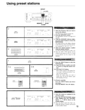
... a total of 30 stations can - While the MEMORY indicator lights, press the GROUP button to receive by using the number buttons. Use the 0/10 number button to store in the memory. (See Receiving stations on the channel display. • Once the preset station has been can be... received for 5 seconds (for 8 seconds. 3. Recalling preset stations 1. Press the PRESET (-4 or lo-) button. MHz ...
... a total of 30 stations can - While the MEMORY indicator lights, press the GROUP button to receive by using the number buttons. Use the 0/10 number button to store in the memory. (See Receiving stations on the channel display. • Once the preset station has been can be... received for 5 seconds (for 8 seconds. 3. Recalling preset stations 1. Press the PRESET (-4 or lo-) button. MHz ...
Owner Manual
Page 20
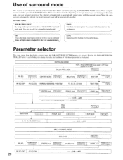
... II . • L-SUR. All input sound is output from the front speakers directly LIVE Reproduces the feeling of a concert hall. Use of surround mode This receiver is provided with 3 kinds of whichever parameter is displayed.
... II . • L-SUR. All input sound is output from the front speakers directly LIVE Reproduces the feeling of a concert hall. Use of surround mode This receiver is provided with 3 kinds of whichever parameter is displayed.

Owner Manual
Page 22
... MODE button to adjust the level. 10. The level values set in Dolby Pro Logic mode will be shown at a large cinema. to put the receiver in a small room, set it. The letters "MULTICH" appear on page 21. If they will be over!): emphasized. resulting in this surround mode. Press the...
... MODE button to adjust the level. 10. The level values set in Dolby Pro Logic mode will be shown at a large cinema. to put the receiver in a small room, set it. The letters "MULTICH" appear on page 21. If they will be over!): emphasized. resulting in this surround mode. Press the...
Owner Manual
Page 23
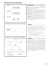
... front left and right speakers in Dolby Pro Logic Surround, three different modes are available for your mom. WIDEBAND Front L ch. The center speaker will receive the full frequency range. L1-L2=1:15 to 23 msec L1-L2=2:16 to 26 msec L1-L2=3:19 to 29 msec L1-L2=4:22...
... front left and right speakers in Dolby Pro Logic Surround, three different modes are available for your mom. WIDEBAND Front L ch. The center speaker will receive the full frequency range. L1-L2=1:15 to 23 msec L1-L2=2:16 to 26 msec L1-L2=3:19 to 29 msec L1-L2=4:22...


