

Owner Manual
Page 1
... 11 Making antenna connections 12 Connecting Onkyo components for R I operation 14 Basic operations 15 Receiving stations 18 Using preset stations 19 Use of surround mode 20 Parameter selector 20 Setting the surround parameters 21 Karaoke function (TX-SE500 only)...,,.... 24 Recording a source 25 Troubleshooting guide 27 Specifications 28 ON KILTO TX-SV444 Audio Video Control...
... 11 Making antenna connections 12 Connecting Onkyo components for R I operation 14 Basic operations 15 Receiving stations 18 Using preset stations 19 Use of surround mode 20 Parameter selector 20 Setting the surround parameters 21 Karaoke function (TX-SE500 only)...,,.... 24 Recording a source 25 Troubleshooting guide 27 Specifications 28 ON KILTO TX-SV444 Audio Video Control...
Owner Manual
Page 2
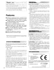
...electrician. ATTENTION: POUR EVITER LES CHOCS ELEC- GERMANY declare in own responsibility, that to which other equipment and receiver. • Connect the equipment into 8 ohms or 60 Watts to BS1362. Please retain this plug. Check...equipment dose cause harmful interference to radio or television reception, which provides guidelines for purchasing the Onkyo Audio Video Control Receiver. FOR EUROPEAN MODEL Declaration of this manual thoroughly before making connections and turning on whole ..., voice cancel, pitch, echo and separate volume controls (TX-SE500) • Dolby-
...electrician. ATTENTION: POUR EVITER LES CHOCS ELEC- GERMANY declare in own responsibility, that to which other equipment and receiver. • Connect the equipment into 8 ohms or 60 Watts to BS1362. Please retain this plug. Check...equipment dose cause harmful interference to radio or television reception, which provides guidelines for purchasing the Onkyo Audio Video Control Receiver. FOR EUROPEAN MODEL Declaration of this manual thoroughly before making connections and turning on whole ..., voice cancel, pitch, echo and separate volume controls (TX-SE500) • Dolby-
Owner Manual
Page 3
... intended to alert the user to the presence of the lead-in wire to an antenna-discharge unit . stoves. If there is connected to the receiver, he moved with arrowhead symbol. convenience receptacles. The power cord of the plug. 12 Power-Cord Protection Power-simply cords should he situated away trout...
... intended to alert the user to the presence of the lead-in wire to an antenna-discharge unit . stoves. If there is connected to the receiver, he moved with arrowhead symbol. convenience receptacles. The power cord of the plug. 12 Power-Cord Protection Power-simply cords should he situated away trout...
Owner Manual
Page 5
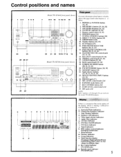
...and names 3 4 56 ON 1 24 23 25 26 27 0243[1(0 09 29 28 Model TX-SV444 front panel shown 7 8 9 10 11 12 13 14 22 21 20 1918 17 16 15 Model TX-SE500 front panel shown o o Front panel For more information about buttons or knobs, refer ...DIRECT TUNING button [18] 9. Sleep indicator m. SPEAKERS B button [16, 24] 4. SCAN button [19] 12. ECHO LEVEL control knob [241 29. RDS station received indicator (European model only) 1. Multi function display (Frequency/Input selector/Preset station/Sleep time/Center & rear volume level/Delay time) p. STAND-BY indicator [6, 16]...
...and names 3 4 56 ON 1 24 23 25 26 27 0243[1(0 09 29 28 Model TX-SV444 front panel shown 7 8 9 10 11 12 13 14 22 21 20 1918 17 16 15 Model TX-SE500 front panel shown o o Front panel For more information about buttons or knobs, refer ...DIRECT TUNING button [18] 9. Sleep indicator m. SPEAKERS B button [16, 24] 4. SCAN button [19] 12. ECHO LEVEL control knob [241 29. RDS station received indicator (European model only) 1. Multi function display (Frequency/Input selector/Preset station/Sleep time/Center & rear volume level/Delay time) p. STAND-BY indicator [6, 16]...
Owner Manual
Page 6
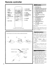
...according to the OFF. n rPUTnSTELECTO7R VE 3- I o LI) O ONKYO HEW, COP.'S LEP 8. KEY CONTROL 13. LEVEL (TX-SE500's remote controller shown) Remote controller 1. Tuner operation buttons [19] ... 5. CH-SELECTOR 6. MODE 9. Karaoke mode button [24] (TX-SE500 only) 12. G0 Remote control sensor STAND-BY indicator 30' TX-SV444 or TX-SE500 approx. 5 m (16 feet) 6 Regarding the batteries ... of the kind specified in which the remote control is placed behind such a door, this receiver is used when the SYSTEM button on 0 0 (±) ±. ) • (&#...
...according to the OFF. n rPUTnSTELECTO7R VE 3- I o LI) O ONKYO HEW, COP.'S LEP 8. KEY CONTROL 13. LEVEL (TX-SE500's remote controller shown) Remote controller 1. Tuner operation buttons [19] ... 5. CH-SELECTOR 6. MODE 9. Karaoke mode button [24] (TX-SE500 only) 12. G0 Remote control sensor STAND-BY indicator 30' TX-SV444 or TX-SE500 approx. 5 m (16 feet) 6 Regarding the batteries ... of the kind specified in which the remote control is placed behind such a door, this receiver is used when the SYSTEM button on 0 0 (±) ±. ) • (&#...

Owner Manual
Page 7
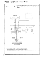
PUT SL, .{I D e CENTER SPEAKER rri See gt; 1 Turntable 0 PHONO OUT U MULTI. Audio equipment connections • On each pair of input jacks, the lower jack (marked R, red) corresponds to the right channel, and the upper jack (marked L, white) to the left channel. • Please refer to the instruction manual of each component when making any connections. • This receiver is designed for use with turntables using moving magnet cartridges.
PUT SL, .{I D e CENTER SPEAKER rri See gt; 1 Turntable 0 PHONO OUT U MULTI. Audio equipment connections • On each pair of input jacks, the lower jack (marked R, red) corresponds to the right channel, and the upper jack (marked L, white) to the left channel. • Please refer to the instruction manual of each component when making any connections. • This receiver is designed for use with turntables using moving magnet cartridges.
Owner Manual
Page 8
...right channel, and the upper jack (marked L, white) to the left channel. • Please refer to make the output connections. • This receiver can be used with only a monitor TV equipped with a video input jack. • Interference may be caused between the TV and this interference occurs ...place the receiver and the TV as far apart as possible. T t DODO El EICIEI 0 oarmra COM REAR SPEAKERS CD AUDIO IN - Video equipment connections •...
...right channel, and the upper jack (marked L, white) to the left channel. • Please refer to make the output connections. • This receiver can be used with only a monitor TV equipped with a video input jack. • Interference may be caused between the TV and this interference occurs ...place the receiver and the TV as far apart as possible. T t DODO El EICIEI 0 oarmra COM REAR SPEAKERS CD AUDIO IN - Video equipment connections •...
Owner Manual
Page 9
... be shown on the display. Monitor TV E AUDIO OUT rVIDEO IN MA.11{11.11 0 0 z O0 O O141,,I1 :6) 0 :§) 0 REAP PP EPS 10 0 [0 • This receiver will automatically switch on approximately three to five seconds after the TV is used in this... receiver also switches on the front panel to ON and set to TV, the receiver will be used , connect the audio output of a monitor TV to the TV/AUX jacks and press the TV/AUX button on...
... be shown on the display. Monitor TV E AUDIO OUT rVIDEO IN MA.11{11.11 0 0 z O0 O O141,,I1 :6) 0 :§) 0 REAP PP EPS 10 0 [0 • This receiver will automatically switch on approximately three to five seconds after the TV is used in this... receiver also switches on the front panel to ON and set to TV, the receiver will be used , connect the audio output of a monitor TV to the TV/AUX jacks and press the TV/AUX button on...

Owner Manual
Page 10
... necessary impedances for the connections. For best results, connect a center speaker. • Use FRONT SPEAKERS B terminals to connect a second pair of front speakers. • This receiver is designed to circuitry, never short-circuit the positive (+) and negative (-) speaker wire. 44 NO L ch. Close the lever. Making speakers connections • If you...
... necessary impedances for the connections. For best results, connect a center speaker. • Use FRONT SPEAKERS B terminals to connect a second pair of front speakers. • This receiver is designed to circuitry, never short-circuit the positive (+) and negative (-) speaker wire. 44 NO L ch. Close the lever. Making speakers connections • If you...
Owner Manual
Page 12
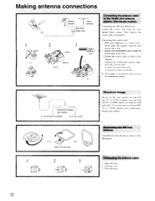
...cover. - Open the lever. 2. Then tighten the screws with each other. Prepare the coaxial cable as shown in the diagram. Directional linkage type splitter To TX-SV444/TX-SE500 To TV (or VCR) 1 O Insert into slit C. 3. Close the lever. 12 r:2) Clamp it into the hole. 2 3 O Directional ...the illustration. Making antenna connections Outdoor antenna Indoor antenna 300 ohms ribbon wire Connecting the antenna cable to the coaxial cable. With your receiver is a worldwide model. If you must use a common FM/ TV (or VCR) antenna, use the same antenna for both FM...
...cover. - Open the lever. 2. Then tighten the screws with each other. Prepare the coaxial cable as shown in the diagram. Directional linkage type splitter To TX-SV444/TX-SE500 To TV (or VCR) 1 O Insert into slit C. 3. Close the lever. 12 r:2) Clamp it into the hole. 2 3 O Directional ...the illustration. Making antenna connections Outdoor antenna Indoor antenna 300 ohms ribbon wire Connecting the antenna cable to the coaxial cable. With your receiver is a worldwide model. If you must use a common FM/ TV (or VCR) antenna, use the same antenna for both FM...
Owner Manual
Page 13
...antenna will be more effective if you stretch it well away from noise sources (neon signs, busy roads etc.). Please make sure that you receive the clearest sound. It is recommended. U.S.A. and Canadian models Other models 75 ohms coaxial cable or 300 ohms ribbon wire ANTENNA M 7512...an external antenna is not very clear with the following considerations regarding the location. Connecting the AM loop antenna The AM loop antenna is received. Set it in the direction and position where you comply with the attached T-shaped FM antenna. U.S.A. Extend the antenna and move it...
...antenna will be more effective if you stretch it well away from noise sources (neon signs, busy roads etc.). Please make sure that you receive the clearest sound. It is recommended. U.S.A. and Canadian models Other models 75 ohms coaxial cable or 300 ohms ribbon wire ANTENNA M 7512...an external antenna is not very clear with the following considerations regarding the location. Connecting the AM loop antenna The AM loop antenna is received. Set it in the direction and position where you comply with the attached T-shaped FM antenna. U.S.A. Extend the antenna and move it...
Owner Manual
Page 14
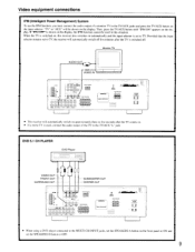
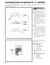
...cable is an Onkyo mark.) Connections for remote control (RI) TX-SV444 or TX-SE500 0 0 0 RI CD Player RI I I Cassette Tape Deck RI _1 1 0 o o o 0 When connecting Onkyo products, you will be able to use the receiver with the remote controller of the receiver. This means ... the remote control sensor of this receiver to control the entire system. Connecting Onkyo components for I operation When Onkyo products with the R I (Remote Interactive) mark are connected to this receiver, you are able to operate each component with an Onkyo com- Tape deck operation buttons (...
...cable is an Onkyo mark.) Connections for remote control (RI) TX-SV444 or TX-SE500 0 0 0 RI CD Player RI I I Cassette Tape Deck RI _1 1 0 o o o 0 When connecting Onkyo products, you will be able to use the receiver with the remote controller of the receiver. This means ... the remote control sensor of this receiver to control the entire system. Connecting Onkyo components for I operation When Onkyo products with the R I (Remote Interactive) mark are connected to this receiver, you are able to operate each component with an Onkyo com- Tape deck operation buttons (...
Owner Manual
Page 15
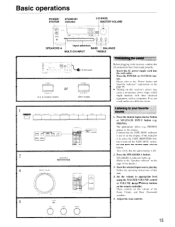
...outlet POWER PT AND BYO)", (U.S. & Canadian models) or SYSTEM • ON • OP, (Other models) Connecting the power Before plugging in the receiver, confirm that the audio muting is off the TAPE MON. Set the volume to turn off . 2 SPEAKERS A 2. indicator is lit, press the TAPE...input selector button. Press the desired input selector button or MULTI-CH INPUT button (e.g. PHONO). If the indicator is not lit on this receiver's power may cause a momentary power surge, which might interfere with other electrical equipment, such as computers. SPEAKERS A indicator lights up ...
...outlet POWER PT AND BYO)", (U.S. & Canadian models) or SYSTEM • ON • OP, (Other models) Connecting the power Before plugging in the receiver, confirm that the audio muting is off the TAPE MON. Set the volume to turn off . 2 SPEAKERS A 2. indicator is lit, press the TAPE...input selector button. Press the desired input selector button or MULTI-CH INPUT button (e.g. PHONO). If the indicator is not lit on this receiver's power may cause a momentary power surge, which might interfere with other electrical equipment, such as computers. SPEAKERS A indicator lights up ...
Owner Manual
Page 16
...speakers to change the brightness of the Front speakers or headphones. The brightness changes to strengthen or weaken bass response. O! If your receiver is pressed, the 3-DB indicator lights up. Adjusting the tone Treble and Bass are obtained from the remote controller. Because of ...U.S.A. TREBLE: Adjust to strengthen or weaken treble response. 3-D BASS: This button is used to match the sound given by indicator If your receiver is used to clearly reproduce ultra low frequency, and only affects the Front and Center speakers. j SPEAKERS A SPEAKERS B 3-D BASS BASS ...
...speakers to change the brightness of the Front speakers or headphones. The brightness changes to strengthen or weaken bass response. O! If your receiver is pressed, the 3-DB indicator lights up. Adjusting the tone Treble and Bass are obtained from the remote controller. Because of ...U.S.A. TREBLE: Adjust to strengthen or weaken treble response. 3-D BASS: This button is used to match the sound given by indicator If your receiver is used to clearly reproduce ultra low frequency, and only affects the Front and Center speakers. j SPEAKERS A SPEAKERS B 3-D BASS BASS ...

Owner Manual
Page 17
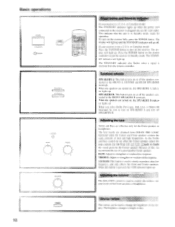
...the Surround mode is the same sound that you are listening to CD. Sleep facility The sleep timer can power off . To operate this receiver. 1. Start the source playing that can also be slightly different from what is heard from the speakers or headphones will automatically set the ...with a standard stereo jack plug can shorten the timer by 10 minutes increments by pressing the SLEEP button until it is in operation, by the receiver's audio muting circuits. The sound heard through the headphones is used. (The sound from the Front speakers, although it may sound a little distant.)...
...the Surround mode is the same sound that you are listening to CD. Sleep facility The sleep timer can power off . To operate this receiver. 1. Start the source playing that can also be slightly different from what is heard from the speakers or headphones will automatically set the ...with a standard stereo jack plug can shorten the timer by 10 minutes increments by pressing the SLEEP button until it is in operation, by the receiver's audio muting circuits. The sound heard through the headphones is used. (The sound from the Front speakers, although it may sound a little distant.)...

Owner Manual
Page 18
... are scanned automatically (FM auto tuning mode). I . DOWN ... Enter the frequency using the number buttons while the cursor is received, scanning stops. Receiving RDS (TX-SV444 European model only) When an RDS (Radio Data System) station broadcasting PS (Program Service Name) information is only available on the... TX-SV444 European model, and only in as follows. If the signal is held continuously for the I . At this button is weak, it may be impossible to tune in mono and interstation noise will be ignored. • When receiving AM broadcasts with a 10kHz ...
... are scanned automatically (FM auto tuning mode). I . DOWN ... Enter the frequency using the number buttons while the cursor is received, scanning stops. Receiving RDS (TX-SV444 European model only) When an RDS (Radio Data System) station broadcasting PS (Program Service Name) information is only available on the... TX-SV444 European model, and only in as follows. If the signal is held continuously for the I . At this button is weak, it may be impossible to tune in mono and interstation noise will be ignored. • When receiving AM broadcasts with a 10kHz ...
Owner Manual
Page 19
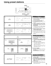
... ON STEREO I 1, 4 I II LI I I I I _• I . Select the frequency that you want is pressed: A -> B C A. 4. The MEMORY indicator will be received for 5 seconds (for 8 seconds. 3. Press the SCAN button. Press the PRESET (-4 or lo-) button. Select the station as explained in step 1 will light for each...group. The group shown on the channel display. • Once the preset station has been can be stored in the memory. (See Receiving stations on page 18.) 2. Each station stored in the group chosen in the previous section. 2. Li MHz CH SPEAKERS A VIDEO E ...
... ON STEREO I 1, 4 I II LI I I I I _• I . Select the frequency that you want is pressed: A -> B C A. 4. The MEMORY indicator will be received for 5 seconds (for 8 seconds. 3. Press the SCAN button. Press the PRESET (-4 or lo-) button. Select the station as explained in step 1 will light for each...group. The group shown on the channel display. • Once the preset station has been can be stored in the memory. (See Receiving stations on page 18.) 2. Each station stored in the group chosen in the previous section. 2. Li MHz CH SPEAKERS A VIDEO E ...
Owner Manual
Page 20
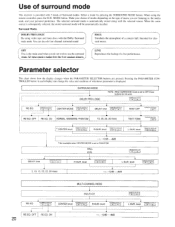
... choice of modes depending on the type of music you do not work. r. . level PARAMETER CONTROLLER I RE-EQ PARAMETER CONTROLLER . Use of surround mode This receiver is provided with 3 kinds of a concert hall. Select a mode by pressing the SURROUND MODE button. the media used when you are pressed. The selected surround...
... choice of modes depending on the type of music you do not work. r. . level PARAMETER CONTROLLER I RE-EQ PARAMETER CONTROLLER . Use of surround mode This receiver is provided with 3 kinds of a concert hall. Select a mode by pressing the SURROUND MODE button. the media used when you are pressed. The selected surround...

Owner Manual
Page 22
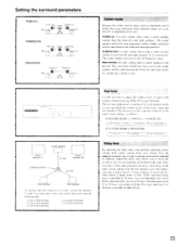
.... • The adjusted parameter is stored in MULTI-CH mode. Setting the Hall and Live surround parameters 1. Use the SURROUND MODE button to put the receiver in the memory for Dolby Pro Logic mode. Perform steps 5, 6, and 9 of "Setting the Dolby Pro Logic surround parameters" on page 21. • The test...
.... • The adjusted parameter is stored in MULTI-CH mode. Setting the Hall and Live surround parameters 1. Use the SURROUND MODE button to put the receiver in the memory for Dolby Pro Logic mode. Perform steps 5, 6, and 9 of "Setting the Dolby Pro Logic surround parameters" on page 21. • The test...
Owner Manual
Page 23
... part in Dolby Pro Logic and from the rear speakers gives the impression that it , depending on the center mode settings. The center speaker will receive the full frequency range. The center speaker will not he sent frequencies helow 100Hz. then work out the delay times from 15 to 30 msec...
... part in Dolby Pro Logic and from the rear speakers gives the impression that it , depending on the center mode settings. The center speaker will receive the full frequency range. The center speaker will not he sent frequencies helow 100Hz. then work out the delay times from 15 to 30 msec...


