
Owners Manual
Page 1
OWNER'S MANUAL 58CM CORDLESS REMOTE LCD TELEVISION & MONITOR MODEL: TFTV580 N111 PALSONIC CORPORATION PTY LTD 1 JOYNTON AVENUE WATERLOO NSW 2017 AUSTRALIA TEL: (02) 9313 7111 FAX: (02) 9313 7555 www.palsonic.com.au PALSONIC CUSTOMER SERVICE TELEPHONE AUSTRALIA: 1300 657 888
OWNER'S MANUAL 58CM CORDLESS REMOTE LCD TELEVISION & MONITOR MODEL: TFTV580 N111 PALSONIC CORPORATION PTY LTD 1 JOYNTON AVENUE WATERLOO NSW 2017 AUSTRALIA TEL: (02) 9313 7111 FAX: (02) 9313 7555 www.palsonic.com.au PALSONIC CUSTOMER SERVICE TELEPHONE AUSTRALIA: 1300 657 888
Owners Manual
Page 2
... ...20 Troubleshooting ...21 Specification ...22 Manual Search ...14 Fine Tuning ...14 To Skip Unnecessary Channel 14 Channel Selection ...15 Using Keypad Buttons ...15 Using CH+/- Contents Important Safety Precautions ...1 Control Panel and Back Terminals 4 Control Panel ...4 Back Terminals ...5 Remote Control Unit ...6 Installation ...8 Antenna Connection ...8 Power Connection ...8 Connecting External Device 9 Basic Operations ...13 Turning On ...13 Turning Off ...13 Selecting Input Signal ...13 Menu Operations ...13 Setting OSD (On-Screen Display 13 Channel Setting ...14 Auto Search...
... ...20 Troubleshooting ...21 Specification ...22 Manual Search ...14 Fine Tuning ...14 To Skip Unnecessary Channel 14 Channel Selection ...15 Using Keypad Buttons ...15 Using CH+/- Contents Important Safety Precautions ...1 Control Panel and Back Terminals 4 Control Panel ...4 Back Terminals ...5 Remote Control Unit ...6 Installation ...8 Antenna Connection ...8 Power Connection ...8 Connecting External Device 9 Basic Operations ...13 Turning On ...13 Turning Off ...13 Selecting Input Signal ...13 Menu Operations ...13 Setting OSD (On-Screen Display 13 Channel Setting ...14 Auto Search...
Owners Manual
Page 4
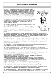
... the power cord from the wall outlet and disconnect the antenna. Safety checks --- In case the product needs replacement parts, make sure that the service person uses replacement parts specified by the manufacturer, or sold with the apparatus. Do not touch the controls other than those with the cart, stand, tripod, bracket, or table specified by the manufacturer, or those described in the instructions can cause...
... the power cord from the wall outlet and disconnect the antenna. Safety checks --- In case the product needs replacement parts, make sure that the service person uses replacement parts specified by the manufacturer, or sold with the apparatus. Do not touch the controls other than those with the cart, stand, tripod, bracket, or table specified by the manufacturer, or those described in the instructions can cause...

Owners Manual
Page 5
.... Power source --- If you finely detailed pictures. When the unit has to be supplied by a listed power supply indicated on the screen as to be located in the vicinity of overhead power lines or other electric light or power circuits, or where it can break when the product is grounded so as a fixed point of glass. This product is made of blue, green or red.
.... Power source --- If you finely detailed pictures. When the unit has to be supplied by a listed power supply indicated on the screen as to be located in the vicinity of overhead power lines or other electric light or power circuits, or where it can break when the product is grounded so as a fixed point of glass. This product is made of blue, green or red.
Owners Manual
Page 6
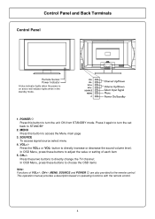
... operation manual provides a description based on and a red indicator lights when in the standby mode. 1. Control Panel and Back Terminals Control Panel Remote Sensor Power Indicator A blue indicator lights when the power is on operating functions with the remote control. 4 SOURCE To access signal source select menu 4. CH+/Press these buttons to adjust the value or setting of VOL+/-, CH+/-, MENU, SOURCE and POWER are also provided to choose the OSD items Note: Functions of each item 5. MENU Press this button to turn...
... operation manual provides a description based on and a red indicator lights when in the standby mode. 1. Control Panel and Back Terminals Control Panel Remote Sensor Power Indicator A blue indicator lights when the power is on operating functions with the remote control. 4 SOURCE To access signal source select menu 4. CH+/Press these buttons to adjust the value or setting of VOL+/-, CH+/-, MENU, SOURCE and POWER are also provided to choose the OSD items Note: Functions of each item 5. MENU Press this button to turn...

Owners Manual
Page 7
... or DVD player. 4. AV outputs (Video, Audio L, R) Connect to the VCR input jacks to the audio and component output jacks of a DVD player or Set-Top Box. 5 Receive a S-Video signal from external sources such as VCR or DVD player. 5. AV2 inputs (Video, Audio L, R) Receive video/audio signals from external source such as VCR or DVD player. Headphone jack 3. Control Panel and Back Terminals Back Terminals AUDIO VGA VGA IN LINE Y PB COMPONENT PR IN 1. COMPONENT inputs (Y, Pb, Pr, Audio L, R) Connect to record programs. 6. VGA input/Audio line in Connect to connect cable or outdoor...
... or DVD player. 4. AV outputs (Video, Audio L, R) Connect to the VCR input jacks to the audio and component output jacks of a DVD player or Set-Top Box. 5 Receive a S-Video signal from external sources such as VCR or DVD player. 5. AV2 inputs (Video, Audio L, R) Receive video/audio signals from external source such as VCR or DVD player. Headphone jack 3. Control Panel and Back Terminals Back Terminals AUDIO VGA VGA IN LINE Y PB COMPONENT PR IN 1. COMPONENT inputs (Y, Pb, Pr, Audio L, R) Connect to record programs. 6. VGA input/Audio line in Connect to connect cable or outdoor...

Owners Manual
Page 8
Setting sleep timer 6 Remote Control Unit Mute Direct channel selector Channel up/down selector Stereo mode select Auto correct picture in VGA LEFT/RIGHT button: In the menu operation, adjust the selected item Access the menu Select the input signal source Power on/standby Previous channel Volume up/down selector Sound mode select Picture mode select Display the current state UP/DOWN button: In menu operations, used to select item.
Setting sleep timer 6 Remote Control Unit Mute Direct channel selector Channel up/down selector Stereo mode select Auto correct picture in VGA LEFT/RIGHT button: In the menu operation, adjust the selected item Access the menu Select the input signal source Power on/standby Previous channel Volume up/down selector Sound mode select Picture mode select Display the current state UP/DOWN button: In menu operations, used to select item.

Owners Manual
Page 9
... lamp or any other strong light shines on the left. 6. Do not mix different types of batteries in the figure on the remote sensor of the TV, the remote operation can be used for the Remote Control If the remote control fails to operate the LCD TV functions, replace the batteries in the remote control. 1 Open the battery cover. 2 Insert two size-AAA batteries. (Place the batteries...
... lamp or any other strong light shines on the left. 6. Do not mix different types of batteries in the figure on the remote sensor of the TV, the remote operation can be used for the Remote Control If the remote control fails to operate the LCD TV functions, replace the batteries in the remote control. 1 Open the battery cover. 2 Insert two size-AAA batteries. (Place the batteries...

Owners Manual
Page 10
... should not be bundled with the power cord and the like. Power connection AC-INPUT bottom view AC cord Household power outlet Plug into AC outlet 1. The AC plug may occur due to eliminate interference and noise which may be operated only from power outlet when not not using for reference only. Installation Antenna Connection Optimum reception of colour requires a good signal and will depend upon your...
... should not be bundled with the power cord and the like. Power connection AC-INPUT bottom view AC cord Household power outlet Plug into AC outlet 1. The AC plug may occur due to eliminate interference and noise which may be operated only from power outlet when not not using for reference only. Installation Antenna Connection Optimum reception of colour requires a good signal and will depend upon your...
Owners Manual
Page 11
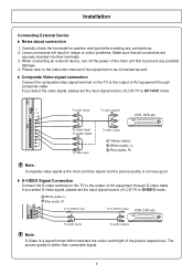
...input To audio inputs R To video output AUDIO W Y Yellow (video) Y To video input W White (audio, L) R Red (audio, R) Note: Composite video signal is the most common signal, but the picture quality is not very good. When connecting an external device, turn off the power of LCD-TV to the output of AV equipment through S-video cable. Composite Video signal connection Connect the composite video signal terminal on the TV to SVIDEO mode. To audio inputs R W To audio outputs R W VCR, DVD etc. W White (audio, L) R Red (audio, R) To S-VIDEO input R W To audio inputs To S-VIDEO...
...input To audio inputs R To video output AUDIO W Y Yellow (video) Y To video input W White (audio, L) R Red (audio, R) Note: Composite video signal is the most common signal, but the picture quality is not very good. When connecting an external device, turn off the power of LCD-TV to the output of AV equipment through S-video cable. Composite Video signal connection Connect the composite video signal terminal on the TV to SVIDEO mode. To audio inputs R W To audio outputs R W VCR, DVD etc. W White (audio, L) R Red (audio, R) To S-VIDEO input R W To audio inputs To S-VIDEO...

Owners Manual
Page 12
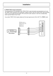
... set the vertical scanning frequency for PC signals to 60Hz. The native display resolution is 1280 768. If you set the input signal source of PC equipment through Min D-sub 15 pin cable as illustrated. Connect a cable, which matches the audio output terminal on the TV to the output of LCD-TV to RGB mode. To VGA output To audio output To VGA input To audio input Equipment with sufficient clarity. 2. Installation The PC input signal connection Connect...
... set the vertical scanning frequency for PC signals to 60Hz. The native display resolution is 1280 768. If you set the input signal source of PC equipment through Min D-sub 15 pin cable as illustrated. Connect a cable, which matches the audio output terminal on the TV to the output of LCD-TV to RGB mode. To VGA output To audio output To VGA input To audio input Equipment with sufficient clarity. 2. Installation The PC input signal connection Connect...
Owners Manual
Page 13
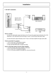
... OUT connection Installation Y Yellow (video) W White (audio, L) R Red (audio, R) To audio inputs R W Audio amplifier To audio outputs AUDIO R W To audio input Y R To video output W Y To video input VCR How to connect: Connect the video/audio output terminals on the TV set to the signal input terminals of the Audio amplifier to minimum. 2. How to begin recording. Turn the volume of the VCR equipment or the video/audio input terminals on the LCD TV and select program. 2. Turn on the TV set through audio cable. Connect the audio output terminals on the LCD TV...
... OUT connection Installation Y Yellow (video) W White (audio, L) R Red (audio, R) To audio inputs R W Audio amplifier To audio outputs AUDIO R W To audio input Y R To video output W Y To video input VCR How to connect: Connect the video/audio output terminals on the TV set to the signal input terminals of the Audio amplifier to minimum. 2. How to begin recording. Turn the volume of the VCR equipment or the video/audio input terminals on the LCD TV and select program. 2. Turn on the TV set through audio cable. Connect the audio output terminals on the LCD TV...
Owners Manual
Page 14
Please connect it with the YPbPr/YCbCr input terminals on the TV set for better picture quality. And connect the audio outputs of the LCD-TV to use the YPbPr/YCbCr terminals on the equipment. White (audio, L) Red (audio, R/Pr) Green (Y) Blue (Pb) DVD, STB etc. 12 If you to YPbPr mode. Installation YPbPr/YCbCr input connection If the signal/source is the equipment with YPbPr/YCbCr output terminals, we recommend you select YPbPr/YCbCr signal, please set the input signal source of it with the corresponding audio input terminals on the TV set .
Please connect it with the YPbPr/YCbCr input terminals on the TV set for better picture quality. And connect the audio outputs of the LCD-TV to use the YPbPr/YCbCr terminals on the equipment. White (audio, L) Red (audio, R/Pr) Green (Y) Blue (Pb) DVD, STB etc. 12 If you to YPbPr mode. Installation YPbPr/YCbCr input connection If the signal/source is the equipment with YPbPr/YCbCr output terminals, we recommend you select YPbPr/YCbCr signal, please set the input signal source of it with the corresponding audio input terminals on the TV set .
Owners Manual
Page 15
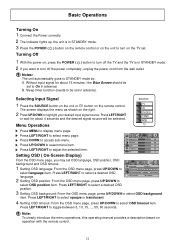
... the desired signal source will be selected. The screen displays the menu as shown on operation with the remote control. 13 Menu Operations Press MENU to select a desired OSD language. Press LEFT/RIGHT to display menu page. Turning Off 1 With the power on, press the POWER ( ) button to turn off the power completely, unplug the power cord from the wall outlet. Selecting Input Signal 1 Press the SOURCE button on the unit or button on the remote control. Press LEFT...
... the desired signal source will be selected. The screen displays the menu as shown on operation with the remote control. 13 Menu Operations Press MENU to select a desired OSD language. Press LEFT/RIGHT to display menu page. Turning Off 1 With the power on, press the POWER ( ) button to turn off the power completely, unplug the power cord from the wall outlet. Selecting Input Signal 1 Press the SOURCE button on the unit or button on the remote control. Press LEFT...
Owners Manual
Page 17
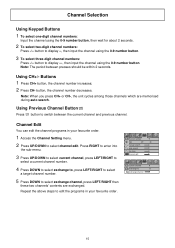
... select a target channel number. 5 Press DOWN to switch between presses should be within 2 seconds. Note: The period between the current channel and previous channel. Buttons 1 Press CH+ button, the channel number increases; 2 Press CH- channel number 9 skip off on manual search auto search fine tune channel edit current channel 9 exchange to select channel edit. Channel Selection Using Keypad Buttons 1 To select one-digit channel numbers: Input the channel using the 0-9 number button. button to edit the programs in your...
... select a target channel number. 5 Press DOWN to switch between presses should be within 2 seconds. Note: The period between the current channel and previous channel. Buttons 1 Press CH+ button, the channel number increases; 2 Press CH- channel number 9 skip off on manual search auto search fine tune channel edit current channel 9 exchange to select channel edit. Channel Selection Using Keypad Buttons 1 To select one-digit channel numbers: Input the channel using the 0-9 number button. button to edit the programs in your...
Owners Manual
Page 19
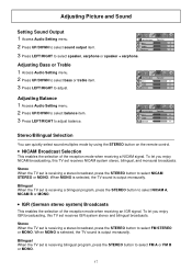
... reception mode when receiving a NICAM signal. sound output Speaker bass 0 treble 0 balance 0 Stereo/Bilingual Selection You can quickly select sound multiplex mode by using the STEREO button on the remote control. NICAM Broadcast Selection This enables the selection of the reception mode when receiving an IGR signal. Bilingual When the TV set is receiving a bilingual program, press the STEREO button to select NICAM STEREO or MONO. Adjusting Bass or Treble 1 Access Audio Setting menu. 2 Press...
... reception mode when receiving a NICAM signal. sound output Speaker bass 0 treble 0 balance 0 Stereo/Bilingual Selection You can quickly select sound multiplex mode by using the STEREO button on the remote control. NICAM Broadcast Selection This enables the selection of the reception mode when receiving an IGR signal. Bilingual When the TV set is receiving a bilingual program, press the STEREO button to select NICAM STEREO or MONO. Adjusting Bass or Treble 1 Access Audio Setting menu. 2 Press...
Owners Manual
Page 20
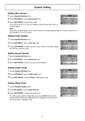
.../RIGHT to select color sys. sound sys. blue screen scaler mode color sys. When the presetting time is no input signal (in standby mode. If you set will turn off fill all Auto B/G 10 minutes Setting Sleep Timer 1 Access System Setting menu. 2 Press UP/DOWN to select sleep time item. 3 Press LEFT/RIGHT to select a proper sound system. item. 3 Press LEFT/RIGHT to select sound sys. sleep time on off . sound sys. sleep time on the remote control. sleep time on off...
.../RIGHT to select color sys. sound sys. blue screen scaler mode color sys. When the presetting time is no input signal (in standby mode. If you set will turn off fill all Auto B/G 10 minutes Setting Sleep Timer 1 Access System Setting menu. 2 Press UP/DOWN to select sleep time item. 3 Press LEFT/RIGHT to select a proper sound system. item. 3 Press LEFT/RIGHT to select sound sys. sleep time on off . sound sys. sleep time on the remote control. sleep time on off...
Owners Manual
Page 21
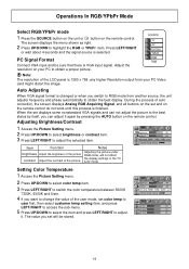
... a proper picture. RGB mode, will be sure that there is finished. Auto Adjusting When VGA signal format is selected. Adjusting Brightness/Contrast 1 Access the Picture Setting menu. 2 Press UP/DOWN to select brightness or contrast item. 3 Press LEFT/RIGHT to adjust it again by itself, you want to change the value of auto correction, the screen displays Analog RGB Acquiring Signal, and all buttons on the remote control do not work until...
... a proper picture. RGB mode, will be sure that there is finished. Auto Adjusting When VGA signal format is selected. Adjusting Brightness/Contrast 1 Access the Picture Setting menu. 2 Press UP/DOWN to select brightness or contrast item. 3 Press LEFT/RIGHT to adjust it again by itself, you want to change the value of auto correction, the screen displays Analog RGB Acquiring Signal, and all buttons on the remote control do not work until...

Owners Manual
Page 22
... to adjust the value of the set's internal clock signal. Operations In RGB/YPbPr Mode Adjusting Phase/Frequency 1 Access the Picture Position menu. 2 Press UP/DOWN to select phase or frequency item. 3 Press LEFT/RIGHT to your PC's Processor. Adjust the clock frequency of the item until the screen is apparent in the image, try adjusting the frequency item. Adjusting Picture Position After connecting the...
... to adjust the value of the set's internal clock signal. Operations In RGB/YPbPr Mode Adjusting Phase/Frequency 1 Access the Picture Position menu. 2 Press UP/DOWN to select phase or frequency item. 3 Press LEFT/RIGHT to your PC's Processor. Adjust the clock frequency of the item until the screen is apparent in the image, try adjusting the frequency item. Adjusting Picture Position After connecting the...
Owners Manual
Page 23
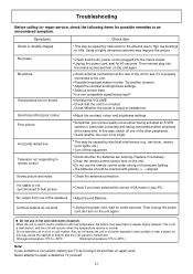
... selected the correct VGA mode in a hot or cold location. Replace if necessary. Do not use the remote control under strong or fluorescent lighting. Is a non-compatible signal being input? Adjust Sound Balance. This is too bright. Select a correct input. Check whether the batteries are working. Then re-plug the power cord and turn on the unit again. Adjust the contrast, colour and brightness settings. Check the antenna connection. This may improve...
... selected the correct VGA mode in a hot or cold location. Replace if necessary. Do not use the remote control under strong or fluorescent lighting. Is a non-compatible signal being input? Adjust Sound Balance. This is too bright. Select a correct input. Check whether the batteries are working. Then re-plug the power cord and turn on the unit again. Adjust the contrast, colour and brightness settings. Check the antenna connection. This may improve...


