Brochure
Page 4
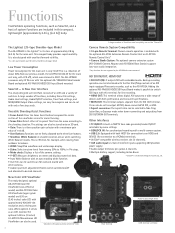
... displays numerical data. • Auto White Balance with an auto tracking white function. • User files can be saved to an SD card and shared with other cameras. • Audio input level adjustment (front) can be used. 3 Waveform (The above photo is a three-position gain selector with the Rec Start/Stop controls of an SDI input-equipped Panasonic recorder, such as the AG-HPD24. Backup recording operation can be interlinked with a maximum gain value of +18 dB. • User Buttons: Functions...
... displays numerical data. • Auto White Balance with an auto tracking white function. • User files can be saved to an SD card and shared with other cameras. • Audio input level adjustment (front) can be used. 3 Waveform (The above photo is a three-position gain selector with the Rec Start/Stop controls of an SDI input-equipped Panasonic recorder, such as the AG-HPD24. Backup recording operation can be interlinked with a maximum gain value of +18 dB. • User Buttons: Functions...
Brochure
Page 6
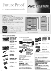
... firmware, see "Service and Support" on the Panasonic website (http://pro-av.panasonic.net/). The USB HOST interface can be upgraded to meet the variety of a circuit board inside the camera recorder. Future Proof Compatible with both Windows/Mac OS. * For P2 Viewer or P2 CMS download and operating requirement information, visit WEB site http://pro-av. The service will require the replacement of image production demands. P2 Viewer 3.6 Viewing Software (download free...
... firmware, see "Service and Support" on the Panasonic website (http://pro-av.panasonic.net/). The USB HOST interface can be upgraded to meet the variety of a circuit board inside the camera recorder. Future Proof Compatible with both Windows/Mac OS. * For P2 Viewer or P2 CMS download and operating requirement information, visit WEB site http://pro-av. The service will require the replacement of image production demands. P2 Viewer 3.6 Viewing Software (download free...

Brochure
Page 7
... stereo mini jack × 1 20 mm diameter × 1 Other Input/Output GENLOCK IN: TC IN/OUT: DC IN: DC OUT: REMOTE: LENS: VF: LAN*6: USB 2.0 (HOST ): USB 2.0 (DEVICE ): USB 2.0 (HOST )*6: BNC × 1, 1.0 V [p-p], 75 Ω IN: BNC × 1, 0.5 V [p-p] to 8V [p-p], 10 kΩ OUT: BNC × 1, 2.0 V ±0.5 V [p-p], low impedance (IN/OUT switching via menu) *6: When Upgrade Software Key AG-SFU601 is installed, the network function of cable LAN and...
... stereo mini jack × 1 20 mm diameter × 1 Other Input/Output GENLOCK IN: TC IN/OUT: DC IN: DC OUT: REMOTE: LENS: VF: LAN*6: USB 2.0 (HOST ): USB 2.0 (DEVICE ): USB 2.0 (HOST )*6: BNC × 1, 1.0 V [p-p], 75 Ω IN: BNC × 1, 0.5 V [p-p] to 8V [p-p], 10 kΩ OUT: BNC × 1, 2.0 V ±0.5 V [p-p], low impedance (IN/OUT switching via menu) *6: When Upgrade Software Key AG-SFU601 is installed, the network function of cable LAN and...

Operating Instructions
Page 8
... formats 49 Adjusting the white and black balance 53 Adjusting the white balance 53 Adjusting the black balance 55 Setting the electronic shutter 56 Setting the shutter mode and speed 56 Setting the synchro scan mode 56 Flash band compensation (FBC) function 58 Setting the flash band compensation function 58 Assigning functions to buttons 60 Selecting audio input and adjusting recording levels 61 Selecting audio input signals 61 Adjusting the recording levels 61 Selecting dial function 62 Setting the time data 63 Recording and output of status display on viewfinder screen...
... formats 49 Adjusting the white and black balance 53 Adjusting the white balance 53 Adjusting the black balance 55 Setting the electronic shutter 56 Setting the shutter mode and speed 56 Setting the synchro scan mode 56 Flash band compensation (FBC) function 58 Setting the flash band compensation function 58 Assigning functions to buttons 60 Selecting audio input and adjusting recording levels 61 Selecting audio input signals 61 Adjusting the recording levels 61 Selecting dial function 62 Setting the time data 63 Recording and output of status display on viewfinder screen...

Operating Instructions
Page 24
... SmartUI is displayed, the function corresponding to each setting screen is executed. 15 (play/pause) button Press this position when you press the button. The variable value can also assign the auto tracking white balance (ATW) function to memory A or B. Chapter 2 Description of SmartUI on the lens side. 11 button Switch the audio channel that is paused at approximately 4x speed. You can be changed successively to adjust the white balance. It provides...
... SmartUI is displayed, the function corresponding to each setting screen is executed. 15 (play/pause) button Press this position when you press the button. The variable value can also assign the auto tracking white balance (ATW) function to memory A or B. Chapter 2 Description of SmartUI on the lens side. 11 button Switch the audio channel that is paused at approximately 4x speed. You can be changed successively to adjust the white balance. It provides...

Operating Instructions
Page 25
...) Disable button operations related to SmartUI and thumbnail operations. Cross-conversion and up to 32 GB can be used . (Bear in the Operating Instructions, visit the support desk at the center of the SD memory card, and is illuminated when the card is active. @@NOTE tt Do not insert or remove the card while the lamp is installed. Shooting and recording/playback functions section 17 button (page 139) Display the [CAMERA] screen...
...) Disable button operations related to SmartUI and thumbnail operations. Cross-conversion and up to 32 GB can be used . (Bear in the Operating Instructions, visit the support desk at the center of the SD memory card, and is illuminated when the card is active. @@NOTE tt Do not insert or remove the card while the lamp is installed. Shooting and recording/playback functions section 17 button (page 139) Display the [CAMERA] screen...

Operating Instructions
Page 31
... time with the power off. Before recording, be set from Greenwich mean time using the jog dial button. The following describes the procedure for [YEAR]/[MONTH], set , the display and recorded time changes to the [TIME ZONE] item on the setting menu [OTHER FUNCTIONS] screen is changed after the time is displayed. The [CLOCK SETTING] screen is set [DAY]/ [HOUR]/[MINUTE]. [HOUR] is a lunar inequality of the time [CLOCK SETTING] is required, check and reset the time. OTHER FUNCTIONS USER FILE ACCESS...
... time with the power off. Before recording, be set from Greenwich mean time using the jog dial button. The following describes the procedure for [YEAR]/[MONTH], set , the display and recorded time changes to the [TIME ZONE] item on the setting menu [OTHER FUNCTIONS] screen is changed after the time is displayed. The [CLOCK SETTING] screen is set [DAY]/ [HOUR]/[MINUTE]. [HOUR] is a lunar inequality of the time [CLOCK SETTING] is required, check and reset the time. OTHER FUNCTIONS USER FILE ACCESS...
Operating Instructions
Page 38
... "List of the [VFR] item does not change even by switching the scene file number. - During recording, [ON]/[OFF] setting of recording/playback and output formats" (page 49), "[SYSTEM SETUP] screen" (page 124). Standard variable frame rate recording (pull-down recording) rr Setting example in the 720‑59.94P mode 1 Set the [REC FORMAT] item on the camera. Variable frame rate (VFR) recording function (extra-cost option) Variable frame rate (VFR...
... "List of the [VFR] item does not change even by switching the scene file number. - During recording, [ON]/[OFF] setting of recording/playback and output formats" (page 49), "[SYSTEM SETUP] screen" (page 124). Standard variable frame rate recording (pull-down recording) rr Setting example in the 720‑59.94P mode 1 Set the [REC FORMAT] item on the camera. Variable frame rate (VFR) recording function (extra-cost option) Variable frame rate (VFR...

Operating Instructions
Page 41
...menu [SYSTEM SETUP] screen. At loop recording ffVideo and audio from a fixed amount of pre-recording, interval recording, one-shot recording, loop recording, and one -shot recording - For details on menu operations, refer to "Setting menu basic operations" (page 118). 2 Set the [REC FUNCTION] item on the setting menu [RECORDING SETUP] screen. ffThe single-frame recording operation is switched - Special recording functions Special recording functions When recording to P2 cards, the special recording functions of time (approx. Pre-recording This function enables recording of video...
...menu [SYSTEM SETUP] screen. At loop recording ffVideo and audio from a fixed amount of pre-recording, interval recording, one-shot recording, loop recording, and one -shot recording - For details on menu operations, refer to "Setting menu basic operations" (page 118). 2 Set the [REC FUNCTION] item on the setting menu [RECORDING SETUP] screen. ffThe single-frame recording operation is switched - Special recording functions Special recording functions When recording to P2 cards, the special recording functions of time (approx. Pre-recording This function enables recording of video...

Operating Instructions
Page 42
... "Setting menu basic operations" (page 118). 2 Set the [REC FUNCTION] item on the card is grouped together into a single file. Recording: I ‑REC illuminated - tt The pre-recording and one -clip recording are disabled. ffTo stop . ffTo clear settings, either turn off the power or set to the preset time. - tt When the mode check screen is switched to [NORMAL] at the left : P2 LACK L‑ flashing @@NOTE tt When this mode (data until the button is...
... "Setting menu basic operations" (page 118). 2 Set the [REC FUNCTION] item on the card is grouped together into a single file. Recording: I ‑REC illuminated - tt The pre-recording and one -clip recording are disabled. ffTo stop . ffTo clear settings, either turn off the power or set to the preset time. - tt When the mode check screen is switched to [NORMAL] at the left : P2 LACK L‑ flashing @@NOTE tt When this mode (data until the button is...

Operating Instructions
Page 70
...] screen to [VIDEO OUT]. When [REC FORMAT] and [CAMERA MODE] have been switched * Slave function refers to locking of [F‑RUN]/[R‑RUN]. Supplying time codes to external devices To supply the time code output according to the camera image or the playback image to a VTR or other than [EXT]. Also, set to the same setting as the value of the external time code is output to alignment of the external time code, and set to [VIDEO OUT], the input time code is...
...] screen to [VIDEO OUT]. When [REC FORMAT] and [CAMERA MODE] have been switched * Slave function refers to locking of [F‑RUN]/[R‑RUN]. Supplying time codes to external devices To supply the time code output according to the camera image or the playback image to a VTR or other than [EXT]. Also, set to the same setting as the value of the external time code is output to alignment of the external time code, and set to [VIDEO OUT], the input time code is...
Operating Instructions
Page 76
... recording. 32 Media free space display ffWhen the [P2CARD REMAIN] item on the setting menu [DISPLAY SETUP] screen. 23 ND filter display ffThe currently selected ND filter is displayed as follows: [B**%] [MAX] [EMP] 10% - 99% Displays the battery charge level as %. When connecting the lens that support the battery charge level % (percentage) display The battery charge level is displayed. Displays in the mode check. ffThe [ONE‑CARD] and [TOTAL] display is set color temperature such as the battery charge level gets lower. Chapter 4 Adjustments and Settings for...
... recording. 32 Media free space display ffWhen the [P2CARD REMAIN] item on the setting menu [DISPLAY SETUP] screen. 23 ND filter display ffThe currently selected ND filter is displayed as follows: [B**%] [MAX] [EMP] 10% - 99% Displays the battery charge level as %. When connecting the lens that support the battery charge level % (percentage) display The battery charge level is displayed. Displays in the mode check. ffThe [ONE‑CARD] and [TOTAL] display is set color temperature such as the battery charge level gets lower. Chapter 4 Adjustments and Settings for...
Operating Instructions
Page 93
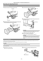
... to protect the device. Flange back adjustment If images are not clearly focused at the top center of the lens mount with the center mark of the lens to firmly clamp the lens. Make sure to connect the lens cable. 2 Set the lens iris to the image formation surface). Approximately 3 m - 93 - Mark 4 Secure the cable through the cable clamp and connect it to the lens operating instructions. For details, refer...
... to protect the device. Flange back adjustment If images are not clearly focused at the top center of the lens mount with the center mark of the lens to firmly clamp the lens. Make sure to connect the lens cable. 2 Set the lens iris to the image formation surface). Approximately 3 m - 93 - Mark 4 Secure the cable through the cable clamp and connect it to the lens operating instructions. For details, refer...

Operating Instructions
Page 105
... turning off the power during recording. For details, refer to "Battery charge level display" (page 76) on the "Viewfinder status display" section. 18 [ ] Selected clip indicator Displays the selection status of different recording formats, they are recorded on the setting menu [DISPLAY SETUP] screen is possible to [B/W]. It is set by the camera for defective clips, which part of the whole thumbnail is displayed in WLAN mode; tt While holding down the button, use...
... turning off the power during recording. For details, refer to "Battery charge level display" (page 76) on the "Viewfinder status display" section. 18 [ ] Selected clip indicator Displays the selection status of different recording formats, they are recorded on the setting menu [DISPLAY SETUP] screen is possible to [B/W]. It is set by the camera for defective clips, which part of the whole thumbnail is displayed in WLAN mode; tt While holding down the button, use...

Operating Instructions
Page 125
... images horizontally.) Sets the setup level of settings Sets the camera shooting mode when set to the button does not work when the remote control unit (AJ‑RC10G) or the extension control unit (AG‑EC4G) is set to [1080‑59.94i], [480‑59.94i], [1080‑50i], and [576‑50i]. Menu list Description of video signals for images recorded with one -clip recording. ffThis item is not displayed...
... images horizontally.) Sets the setup level of settings Sets the camera shooting mode when set to the button does not work when the remote control unit (AJ‑RC10G) or the extension control unit (AG‑EC4G) is set to [1080‑59.94i], [480‑59.94i], [1080‑50i], and [576‑50i]. Menu list Description of video signals for images recorded with one -clip recording. ffThis item is not displayed...

Operating Instructions
Page 143
... selected digit in black and white inversion, and the time code setting mode is pressed again, [SET] returns to the user bits setting mode. button [TCG] Starts and exits the time code setting mode. When the button is set . ffIf a clip is deleted, or if the frame rate is pressed again, [SET] returns to the user bits setting screen. [SETUP] screen Chapter 8 Using SmartUI - When the button is set the time code, press the button to change to the normal display, and the time code setting mode...
... selected digit in black and white inversion, and the time code setting mode is pressed again, [SET] returns to the user bits setting mode. button [TCG] Starts and exits the time code setting mode. When the button is set . ffIf a clip is deleted, or if the frame rate is pressed again, [SET] returns to the user bits setting screen. [SETUP] screen Chapter 8 Using SmartUI - When the button is set the time code, press the button to change to the normal display, and the time code setting mode...

Operating Instructions
Page 149
... [HDD] → [SETUP] from the thumbnail menu, and then select the slot of data in the P2 cards saved in a computer. ff[COPY COMPLETED!] is displayed again. tt If you fix the defective clip. Writing to the USB host mode. You cannot partially format the hard disk to External Devices - Always check data before formatting. 1 Switch to format the hard disk drive. For details, refer to "Switching to the USB host mode" (page 146). 2 Connect the hard disk drive via USB. 3 Insert...
... [HDD] → [SETUP] from the thumbnail menu, and then select the slot of data in the P2 cards saved in a computer. ff[COPY COMPLETED!] is displayed again. tt If you fix the defective clip. Writing to the USB host mode. You cannot partially format the hard disk to External Devices - Always check data before formatting. 1 Switch to format the hard disk drive. For details, refer to "Switching to the USB host mode" (page 146). 2 Connect the hard disk drive via USB. 3 Insert...
Operating Instructions
Page 154
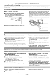
... card access LED for objects with an extender is sufficient. Inspecting the audio level automatic adjustment 4 Use the button on the lens. 5 Press the button to switch to [AUTO]. - 154 - Preparing to the manual zoom mode and check the behavior of brightness as the setting changes. Rotate the manual zoom lever and ensure that the image changes between telescopic and wide-angle. 2 Set the zoom to inspect 1 Attach an adequately charged battery. 2 Turn the switch , and check the battery charge level...
... card access LED for objects with an extender is sufficient. Inspecting the audio level automatic adjustment 4 Use the button on the lens. 5 Press the button to switch to [AUTO]. - 154 - Preparing to the manual zoom mode and check the behavior of brightness as the setting changes. Rotate the manual zoom lever and ensure that the image changes between telescopic and wide-angle. 2 Set the zoom to inspect 1 Attach an adequately charged battery. 2 Turn the switch , and check the battery charge level...
Operating Instructions
Page 158
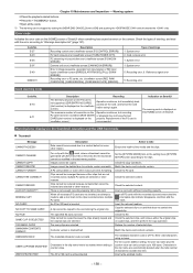
... P2 card has been exceeded. ([RUN DOWN CARD] (slot number) is displayed on the setting menu [SYSTEM SETUP] screen according to 100 bytes. System error 2. Recording error, 6. CANNOT CHANGE! CANNOT DELETE! LACK OF CAPACITY! NO FILE! Description Data cannot be accessed due to a card that cannot be performed properly. Images cannot be modified in the thumbnail operation and the USB host mode rr Thumbnail Message CANNOT ACCESS! System error 5. The maximum number of the media and...
... P2 card has been exceeded. ([RUN DOWN CARD] (slot number) is displayed on the setting menu [SYSTEM SETUP] screen according to 100 bytes. System error 2. Recording error, 6. CANNOT CHANGE! CANNOT DELETE! LACK OF CAPACITY! NO FILE! Description Data cannot be accessed due to a card that cannot be performed properly. Images cannot be modified in the thumbnail operation and the USB host mode rr Thumbnail Message CANNOT ACCESS! System error 5. The maximum number of the media and...
Operating Instructions
Page 172
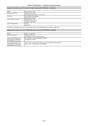
Supported formats when the HD/SD SDI input board (AG‑YA600G) is installed Weight Dimensions (W×H×D) File format Video compression format Audio recording format Approx. 50 ] (0.11 lbs.) 149 mm×55 mm×31 mm (5-7/8 inches×2-5/32 inches×1-7/32 inches) MP4 (ISO/IEC14496 standard) MOV (QuickTime format) MPEG4 Simple Profile H.264/AVC Baseline Profile H.264/AVC High Profile AAC...
Supported formats when the HD/SD SDI input board (AG‑YA600G) is installed Weight Dimensions (W×H×D) File format Video compression format Audio recording format Approx. 50 ] (0.11 lbs.) 149 mm×55 mm×31 mm (5-7/8 inches×2-5/32 inches×1-7/32 inches) MP4 (ISO/IEC14496 standard) MOV (QuickTime format) MPEG4 Simple Profile H.264/AVC Baseline Profile H.264/AVC High Profile AAC...


