
AJCA910 User Guide
Page 1
Audio 4CH Camera Adapter AJ- P Operating Instructions Printed in Japan VQT9058-1 P F1000W @
Audio 4CH Camera Adapter AJ- P Operating Instructions Printed in Japan VQT9058-1 P F1000W @
AJCA910 User Guide
Page 4
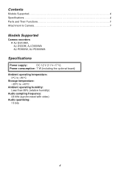
Contents Models Supported 4 Specifications 4 Parts and Their Functions 5 Attachment to Camera 7 Models Supported Camera recorders O AJ-D910WA, AJ-D900W, AJ-D900WA AJ-PD900W, AJ-PD900WA Specifications Power supply: DC 12 V (11 V-17 V) Power consumption: 7 W (including the optional board) Ambient operating temperature: 0°C to +40°C Storage temperature: -20°C to +60°C Ambient operating humidity: Less than 85% (relative humidity) Audio sampling frequency: 48 kHz (synchronized with video) Audio quantizing: 16 bits 4
Contents Models Supported 4 Specifications 4 Parts and Their Functions 5 Attachment to Camera 7 Models Supported Camera recorders O AJ-D910WA, AJ-D900W, AJ-D900WA AJ-PD900W, AJ-PD900WA Specifications Power supply: DC 12 V (11 V-17 V) Power consumption: 7 W (including the optional board) Ambient operating temperature: 0°C to +40°C Storage temperature: -20°C to +60°C Ambient operating humidity: Less than 85% (relative humidity) Audio sampling frequency: 48 kHz (synchronized with video) Audio quantizing: 16 bits 4
AJCA910 User Guide
Page 5
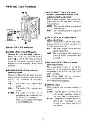
... microphones is supplied. 7 POWER switch This controls the camera adapter's power. AUTO : The recording level is adjusted automatically. Parts and Their Functions 12 POWER STBY SAVE AUDIO IN MIC LINE CH 3 CH 4 MIC POWER ON OFF 53 6 7 4 1 Audio CH 3/CH 4 level meter 2 AUDIO LEVEL CH 3/CH 4 (audio channel 3/4 recording level) controls When the AUDIO SELECT CH 3/CH 4 switch 4 is set to MAN, the recording...
... microphones is supplied. 7 POWER switch This controls the camera adapter's power. AUTO : The recording level is adjusted automatically. Parts and Their Functions 12 POWER STBY SAVE AUDIO IN MIC LINE CH 3 CH 4 MIC POWER ON OFF 53 6 7 4 1 Audio CH 3/CH 4 level meter 2 AUDIO LEVEL CH 3/CH 4 (audio channel 3/4 recording level) controls When the AUDIO SELECT CH 3/CH 4 switch 4 is set to MAN, the recording...
AJCA910 User Guide
Page 6
... connectors. XLR, 3-pin, male +4 dBu (can be used to operate the camera adapter. O Please consult your local dealer or service center when changing the settings of the audio output from the PHONES jack. : AUDIO IN CH 3/CH 4 (audio input channel 3/4) connectors (XLR, 3-pin) The audio component or microphones are connected to -40 dBu using internal switch) Phantom...
... connectors. XLR, 3-pin, male +4 dBu (can be used to operate the camera adapter. O Please consult your local dealer or service center when changing the settings of the audio output from the PHONES jack. : AUDIO IN CH 3/CH 4 (audio input channel 3/4) connectors (XLR, 3-pin) The audio component or microphones are connected to -40 dBu using internal switch) Phantom...
AJCA910 User Guide
Page 7
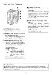
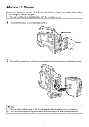
O Take care to avoid pinching the connector cords during the attachment procedure. Attachment to Camera O Consult with the connector pins. 1 Remove the battery mount from the camera. O Take care to avoid damaging the flexible board during the attachment procedure. 7 Battery mount Screws 2 Connect the connectors on the camera unit. O Take care not to the connectors on the camera adapter to make direct contact with your dealer or a Panasonic Service Center representative before attaching this camera adapter.
O Take care to avoid pinching the connector cords during the attachment procedure. Attachment to Camera O Consult with the connector pins. 1 Remove the battery mount from the camera. O Take care to avoid damaging the flexible board during the attachment procedure. 7 Battery mount Screws 2 Connect the connectors on the camera unit. O Take care not to the connectors on the camera adapter to make direct contact with your dealer or a Panasonic Service Center representative before attaching this camera adapter.
AJCA910 User Guide
Page 8
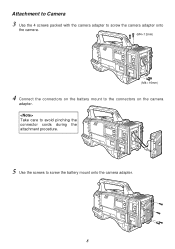
Take care to avoid pinching the connector cords during the attachment procedure. 5 Use the screws to the connectors on the camera adapter. Attachment to Camera 3 Use the 4 screws packed with the camera adapter to screw the camera adapter onto the camera. (M4a12mm) (M4a16mm) 4 Connect the connectors on the battery mount to screw the battery mount onto the camera adapter. 8
Take care to avoid pinching the connector cords during the attachment procedure. 5 Use the screws to the connectors on the camera adapter. Attachment to Camera 3 Use the 4 screws packed with the camera adapter to screw the camera adapter onto the camera. (M4a12mm) (M4a16mm) 4 Connect the connectors on the battery mount to screw the battery mount onto the camera adapter. 8


