

AJD610WA User Guide
Page 1
P Operating Instructions Digital Camera/VTR AJ-
P Operating Instructions Digital Camera/VTR AJ-

AJD610WA User Guide
Page 3
...;Time Code-Related Section 20 ÁWarning/Status Display Section . . . . . 22 Power Supply ÁUsing an Anton Bauer Battery Pack 23 ÁUsing the Panasonic AU-BP402 Battery Pack 24 ÁUsing a Sony Battery Pack 26 ÁUsing the Sony BP-90 Battery Pack 27 ÁUsing the Sony BP...60 ÁDisplay Mode and Setting Change Message 61 ÁChanging the Display Mode 62 ÁSetting the Marker Displays 62 ÁSetting the Camera ID 63 Displays ÁRemaining Battery Level and Audio Level Displays 64 ÁVTR Section Operation/Status-Related Displays 64 ÁTime Code-Related ...
...;Time Code-Related Section 20 ÁWarning/Status Display Section . . . . . 22 Power Supply ÁUsing an Anton Bauer Battery Pack 23 ÁUsing the Panasonic AU-BP402 Battery Pack 24 ÁUsing a Sony Battery Pack 26 ÁUsing the Sony BP-90 Battery Pack 27 ÁUsing the Sony BP...60 ÁDisplay Mode and Setting Change Message 61 ÁChanging the Display Mode 62 ÁSetting the Marker Displays 62 ÁSetting the Camera ID 63 Displays ÁRemaining Battery Level and Audio Level Displays 64 ÁVTR Section Operation/Status-Related Displays 64 ÁTime Code-Related ...

AJD610WA User Guide
Page 4
... (120) ÁMAIN menu screen 2 of 4 (SUB menu 121 VF DISPLAY (121), VF INDICATOR (123), CAMERA ID (124), SHUTTER SPEED (124), SYNCHRO SCAN (125), !LED (125), CAMERA SW MODE (126), SUPER GAIN (127), VTR FUNCTION (128), BATT/TAPE ALARM (130) ÁMAIN menu screen 3 of 4 (... ÁCleaning the Video Heads 150 ÁCleaning the Viewfinder 150 ÁCharacteristic Phenomenon of CCD Cameras 150 Inspections Before Shooting ÁInspection Preparations 151 ÁInspecting the Camera Section 151 ÁInspecting the Viewfinder 152 ÁInspecting the Iris and Zoom Functions 153 Á...
... (120) ÁMAIN menu screen 2 of 4 (SUB menu 121 VF DISPLAY (121), VF INDICATOR (123), CAMERA ID (124), SHUTTER SPEED (124), SYNCHRO SCAN (125), !LED (125), CAMERA SW MODE (126), SUPER GAIN (127), VTR FUNCTION (128), BATT/TAPE ALARM (130) ÁMAIN menu screen 3 of 4 (... ÁCleaning the Video Heads 150 ÁCleaning the Viewfinder 150 ÁCharacteristic Phenomenon of CCD Cameras 150 Inspections Before Shooting ÁInspection Preparations 151 ÁInspecting the Camera Section 151 ÁInspecting the Viewfinder 152 ÁInspecting the Iris and Zoom Functions 153 Á...

AJD610WA User Guide
Page 5
... functions and execute memory card operations, etc. Setting menu The setting menu is also used for 8 different conditions. Features of the Camera Section The camera section of video gain selections Gain values can be set to the user's convenience. In addition, the following features. ÁHigh ... moving subjects. General and Features This unit combines as a single integrated unit a 3-CCD color video camera which features ITCCDs and a 520,000-pixel on-chip lens, and a DVCPRO format VTR which informs the user that the unit has entered irregular status can be easily reproduced and ...
... functions and execute memory card operations, etc. Setting menu The setting menu is also used for 8 different conditions. Features of the Camera Section The camera section of video gain selections Gain values can be set to the user's convenience. In addition, the following features. ÁHigh ... moving subjects. General and Features This unit combines as a single integrated unit a 3-CCD color video camera which features ITCCDs and a 520,000-pixel on-chip lens, and a DVCPRO format VTR which informs the user that the unit has entered irregular status can be easily reproduced and ...
AJD610WA User Guide
Page 6
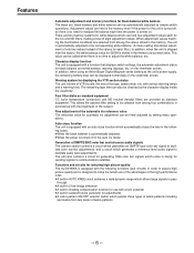
... the power for the unit is turned on. Four filter disks as a preset value. Generation of SMPTE/SNG color bar and reference audio signals The camera section contains a circuit which generates an SMPTE type color bar signal to facilitate color monitor adjustments, and a circuit which can hold four adjustment values each...
... the power for the unit is turned on. Four filter disks as a preset value. Generation of SMPTE/SNG color bar and reference audio signals The camera section contains a circuit which generates an SMPTE type color bar signal to facilitate color monitor adjustments, and a circuit which can hold four adjustment values each...

AJD610WA User Guide
Page 7
...;The audio CH1 recording level can be performed by remote control. -7- Remote control Connecting the Extension Control Unit (option, AQ-EC1) allows a portion of the camera section functions to the main unit using the 26-pin/12-pin output adaptor (option, AJ-YA900P), recording can be easily adjusted at the front...
...;The audio CH1 recording level can be performed by remote control. -7- Remote control Connecting the Extension Control Unit (option, AQ-EC1) allows a portion of the camera section functions to the main unit using the 26-pin/12-pin output adaptor (option, AJ-YA900P), recording can be easily adjusted at the front...

AJD610WA User Guide
Page 9
... EVF WV-VF65B/C Rain cover SHAN-RC700 Soft carrying case AJ-SC900 Tripot mount adaptor (Accessory) Wireless microphone receiver WX-RA700 Shoulder belt Camera/VTR AJ-D610WA 26P/12P output adaptor AJ-YA900P Battery case SHAN-B220 Battery case AU-M402H Battery case/ Battery holder VTR cable VTR ... AU-BP220 Sony Battery NP-1 IDX Battery L-40 Panasonic Battery AU-BP402 Anton Bauer Battery Sony Battery BP-90 BP-L60/BP-L90 Battery charger AG-B425 AC adaptor AJ-B75 Cassette tape ÁM size cassette tape exclusively for DVCPRO Cleaning tape AJ-CL12MP Setup memory card SHL-064HSRVS Picture...
... EVF WV-VF65B/C Rain cover SHAN-RC700 Soft carrying case AJ-SC900 Tripot mount adaptor (Accessory) Wireless microphone receiver WX-RA700 Shoulder belt Camera/VTR AJ-D610WA 26P/12P output adaptor AJ-YA900P Battery case SHAN-B220 Battery case AU-M402H Battery case/ Battery holder VTR cable VTR ... AU-BP220 Sony Battery NP-1 IDX Battery L-40 Panasonic Battery AU-BP402 Anton Bauer Battery Sony Battery BP-90 BP-L60/BP-L90 Battery charger AG-B425 AC adaptor AJ-B75 Cassette tape ÁM size cassette tape exclusively for DVCPRO Cleaning tape AJ-CL12MP Setup memory card SHL-064HSRVS Picture...

AJD610WA User Guide
Page 14
... is set on the setting menu. § Diopter control knob This is adjusted in such a way that those parts with the dioptric power of the camera's operator. ¨ Eye cup © Viewfinder forward-backward/left-right position clamp lever Loosen this lever to adjust the position of the viewfinder ¢ ...accordance with an IRE video level from approx. 70% to 85% are displayed. ON: The zebra pattern is not displayed. It does not affect the camera's output signals. ¥ BRIGHT control This is used to 110% or more or with a certain level can also be set in the viewfinder during ...
... is set on the setting menu. § Diopter control knob This is adjusted in such a way that those parts with the dioptric power of the camera's operator. ¨ Eye cup © Viewfinder forward-backward/left-right position clamp lever Loosen this lever to adjust the position of the viewfinder ¢ ...accordance with an IRE video level from approx. 70% to 85% are displayed. ON: The zebra pattern is not displayed. It does not affect the camera's output signals. ¥ BRIGHT control This is used to 110% or more or with a certain level can also be set in the viewfinder during ...

AJD610WA User Guide
Page 16
... selector) switch This is activated in cases like these settings are output. If the AUTO KNEE function is used when the images shot by the camera are assigned beforehand on the viewfinder screen. (Example: "12 dB") ± AUTO W/B BAL (white balance/black balance automatic adjustment) switch AWB: ... when the display mode has been set to the VTR unit, viewfinder and video monitor. If the setting of this switch is shipped from the camera unit to "3", the new setting will be reproduced in the ranges preset on the viewfinder screen. (Example: ":1/250", ":1/60.8") 1) AUTO KNEE...
... selector) switch This is activated in cases like these settings are output. If the AUTO KNEE function is used when the images shot by the camera are assigned beforehand on the viewfinder screen. (Example: "12 dB") ± AUTO W/B BAL (white balance/black balance automatic adjustment) switch AWB: ... when the display mode has been set to the VTR unit, viewfinder and video monitor. If the setting of this switch is shipped from the camera unit to "3", the new setting will be reproduced in the ranges preset on the viewfinder screen. (Example: ":1/250", ":1/60.8") 1) AUTO KNEE...

AJD610WA User Guide
Page 17
... for mounting method.) The 26-pin/12-pin output adaptor AJ-YA900P (option) is playing back, the camera's images are output at all times. - 17 - Furthermore, by the camera can be checked. ¶ CAM OUT (camera output) connector (BNC) This outputs the composite video signals (75° termination, rated level). While performing settings...
... for mounting method.) The 26-pin/12-pin output adaptor AJ-YA900P (option) is playing back, the camera's images are output at all times. - 17 - Furthermore, by the camera can be checked. ¶ CAM OUT (camera output) connector (BNC) This outputs the composite video signals (75° termination, rated level). While performing settings...
AJD610WA User Guide
Page 18
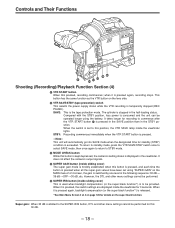
...has the same function as the VTR button on the MAIN menu 2 of 4 on the super black function. It does not affect the camera's output signals. º SUPER GAIN button (inside the viewfinder for 3 seconds. SAVE: This is stopped in the half-loading status. To...Controls and Their Functions ∑ Shooting (Recording)/Playback Function Section (4) · VTR START button When this button is kept depressed, the camera's setting status is displayed in the viewfinder. STBY: Recording commences immediately when the VTR START button is temporarily stopped (REC PAUSE). F1See Main...
...has the same function as the VTR button on the MAIN menu 2 of 4 on the super black function. It does not affect the camera's output signals. º SUPER GAIN button (inside the viewfinder for 3 seconds. SAVE: This is stopped in the half-loading status. To...Controls and Their Functions ∑ Shooting (Recording)/Playback Function Section (4) · VTR START button When this button is kept depressed, the camera's setting status is displayed in the viewfinder. STBY: Recording commences immediately when the VTR START button is temporarily stopped (REC PAUSE). F1See Main...
AJD610WA User Guide
Page 20
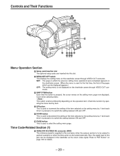
... Their Functions Ã Õ Œ » Menu Operation Section à Setup card insertion slot The optional setup cards are inserted into this connector when the camera section is to be subject to genlock operation or when the time code is to be locked externally. Use it is pressed or to switch...
... Their Functions Ã Õ Œ » Menu Operation Section à Setup card insertion slot The optional setup cards are inserted into this connector when the camera section is to be subject to genlock operation or when the time code is to be locked externally. Use it is pressed or to switch...

AJD610WA User Guide
Page 30
... the lens mount with this unit) - 30 - LENS Connector ÁSee the Handling Instructions provided with the lens for lens handling. |Note{ The lens and camera adjustments listed below may be mounted. 1. Lens flange back adjustment 2. Mark 3 Lower the lens clamping lever and clamp the lens. 4 Press the cable into the...
... the lens mount with this unit) - 30 - LENS Connector ÁSee the Handling Instructions provided with the lens for lens handling. |Note{ The lens and camera adjustments listed below may be mounted. 1. Lens flange back adjustment 2. Mark 3 Lower the lens clamping lever and clamp the lens. 4 Press the cable into the...
AJD610WA User Guide
Page 32
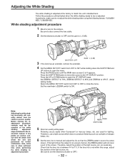
... and adjust the iris so that the lens iris is between F4 to SPOT. (Initial setting mode) Return the MENU SET/OFF switch from the camera's picture quality. GAIN: L (0 dB) 4 Set the MENU SET/OFF switch from whom the unit was purchased for lighting. Set ZEBRA1 DETECT to 70%, ...VF DISPLAY position. SHUTTER: OFF 3 If the lens has an extender, remove the extender. Press the SHIFT/ITEM button to move the cursor to the camera. Note: Adjusting the white shad- adjustment procedure, carefully read the de- If any points are used for further clarification. Be sure to also connect ...
... and adjust the iris so that the lens iris is between F4 to SPOT. (Initial setting mode) Return the MENU SET/OFF switch from the camera's picture quality. GAIN: L (0 dB) 4 Set the MENU SET/OFF switch from whom the unit was purchased for lighting. Set ZEBRA1 DETECT to 70%, ...VF DISPLAY position. SHUTTER: OFF 3 If the lens has an extender, remove the extender. Press the SHIFT/ITEM button to move the cursor to the camera. Note: Adjusting the white shad- adjustment procedure, carefully read the de- If any points are used for further clarification. Be sure to also connect ...

AJD610WA User Guide
Page 33
... of light will drop. - 33 - Adjustment is characteristic of the optical system of 19:9 and 4:3 modes. The adjustment value is stored in 4:3 mode, set the camera to 9 for the unit is operating. However, this method may occur near the open position of 4 appears. Next, execute ABB and then execute AWB again...
... of light will drop. - 33 - Adjustment is characteristic of the optical system of 19:9 and 4:3 modes. The adjustment value is stored in 4:3 mode, set the camera to 9 for the unit is operating. However, this method may occur near the open position of 4 appears. Next, execute ABB and then execute AWB again...

AJD610WA User Guide
Page 41
Connecting an Audio Component When using the Panasonic wireless microphone system, mount the WX-RA700 wireless receiver. To the AUDIO OUT Connector WX-RA700 Wireless Receiver WX-R980 Camera Attachment AUDIO IN switch: Set the AUDIO IN switch of the channel to which the audio signal source is connected to the ... the Handling Instructions for the WX-RA700 wireless receiver for wireless receiver operations. AUDIO IN Switch: Set the AUDIO IN Switch of the camera attachment (1) and detach the microphone in the upward direction (2). Connect to the AUDIO IN CH1 or CH2 Connector.
Connecting an Audio Component When using the Panasonic wireless microphone system, mount the WX-RA700 wireless receiver. To the AUDIO OUT Connector WX-RA700 Wireless Receiver WX-R980 Camera Attachment AUDIO IN switch: Set the AUDIO IN switch of the channel to which the audio signal source is connected to the ... the Handling Instructions for the WX-RA700 wireless receiver for wireless receiver operations. AUDIO IN Switch: Set the AUDIO IN Switch of the camera attachment (1) and detach the microphone in the upward direction (2). Connect to the AUDIO IN CH1 or CH2 Connector.

AJD610WA User Guide
Page 42
...the grooves until a clicking sound is heard. Care should be taken as the camera cannot be mounted if the pin remains in consideration of the unit's and tripod attachment's center of the universal... head's camera mounting screw. In addition, check that the diameter of the selected hole matches the diameter... Black Lever |Note{ When the tripod attachment pin does not return to its original position after the camera has been detached, hold down the red lever and move the black lever in the direction of the...
...the grooves until a clicking sound is heard. Care should be taken as the camera cannot be mounted if the pin remains in consideration of the unit's and tripod attachment's center of the universal... head's camera mounting screw. In addition, check that the diameter of the selected hole matches the diameter... Black Lever |Note{ When the tripod attachment pin does not return to its original position after the camera has been detached, hold down the red lever and move the black lever in the direction of the...

AJD610WA User Guide
Page 46
...connected and the POWER switches of the unit and AQ-EC1 are erased when the unit's POWER switch is connected to an AQ series digital camera. When the AQ-EC1 is connected to the AJ-D610WA, some functions differ, and some features cannot be lost even when the unit's...set to OFF. Connecting the AQ-EC1 Extension Control Unit (Option) Connecting the AQ-EC1 extension control unit (option) allows a portion of the camera section functions to ON, the unit automatically enters remote control mode. The handling instructions included with the menu setting section are saved.) ÁWhen ON...
...connected and the POWER switches of the unit and AQ-EC1 are erased when the unit's POWER switch is connected to an AQ series digital camera. When the AQ-EC1 is connected to the AJ-D610WA, some functions differ, and some features cannot be lost even when the unit's...set to OFF. Connecting the AQ-EC1 Extension Control Unit (Option) Connecting the AQ-EC1 extension control unit (option) allows a portion of the camera section functions to ON, the unit automatically enters remote control mode. The handling instructions included with the menu setting section are saved.) ÁWhen ON...

AJD610WA User Guide
Page 47
...) HIGH SETTING (116) ADDITIONAL DTL (117) SKIN TONE DTL (118) KNEE/LEVEL (119) FLARE/GAMMA (120) CAMERA SETTING (120) VF DISPLAY (121) VF INDICATOR (123) CAMERA ID (124) SHUTTER SPEED (124) SYNCHRO SCAN (125) !LED (125) CAMERA SW MODE (126) SUPER GAIN (127) VTR FUNCTION (128) BATT/TAPE ALARM (130) CARD READ/WRITE...
...) HIGH SETTING (116) ADDITIONAL DTL (117) SKIN TONE DTL (118) KNEE/LEVEL (119) FLARE/GAMMA (120) CAMERA SETTING (120) VF DISPLAY (121) VF INDICATOR (123) CAMERA ID (124) SHUTTER SPEED (124) SYNCHRO SCAN (125) !LED (125) CAMERA SW MODE (126) SUPER GAIN (127) VTR FUNCTION (128) BATT/TAPE ALARM (130) CARD READ/WRITE...
AJD610WA User Guide
Page 52
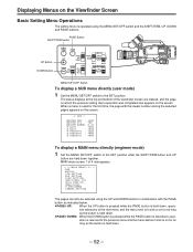
... bottom of 4 now appears. ¢E E E EMA I N MENU 1 / 4 E E E E ROP MATR I X L OW S E T T I NG M I D SET T I NG H I GH SET T I NG ADD I T I ONA L DT L SK I N TONE DT L KNEE / LEVEL F L A R E / GAMMA CAMERA SET T I N : R PEDESTAL : G PEDESTAL : B PEDESTAL : µ0 0 0 µ0 0 0 . 45 µ0 0 0 µ0 0 0 µ0 0 0 µ0 0 0 µ0 0 0 To display a MAIN menu directly (engineer mode) 1 Set the MENU SET/OFF switch...
... bottom of 4 now appears. ¢E E E EMA I N MENU 1 / 4 E E E E ROP MATR I X L OW S E T T I NG M I D SET T I NG H I GH SET T I NG ADD I T I ONA L DT L SK I N TONE DT L KNEE / LEVEL F L A R E / GAMMA CAMERA SET T I N : R PEDESTAL : G PEDESTAL : B PEDESTAL : µ0 0 0 µ0 0 0 . 45 µ0 0 0 µ0 0 0 µ0 0 0 µ0 0 0 µ0 0 0 To display a MAIN menu directly (engineer mode) 1 Set the MENU SET/OFF switch...


